Nibe Solar 42 Installer Manual
For nibe f1145/f1345
Hide thumbs
Also See for Solar 42:
- Installer manual (44 pages) ,
- Installer manual (40 pages) ,
- Installer manual (12 pages)
Table of Contents

Related Manuals for Nibe Solar 42


Summary of Contents for Nibe Solar 42
- Page 1 SOLAR 42 Installatörshandbok SOLAR 42 för NIBE F1145/F1345 Installer manual SOLAR 42 for NIBE F1145/F1345 Installateurhandbuch SOLAR 42 für NIBE F1145/F1345 Asentajan käsikirja SOLAR 42 NIBE F1145/F1345 IHB 1218-2 031887...
-
Page 2: Component Positions
English, Installer manual - SOLAR 42 Component positions General With SOLAR 42, F1145/F1345 together with: VPAS can be connected to solar heating for hot water charging. VPBS (only F1145) is connected to solar heating for hot water charging. VPB/heater for hot water charging via heat exchanger. -
Page 3: Pipe Connections
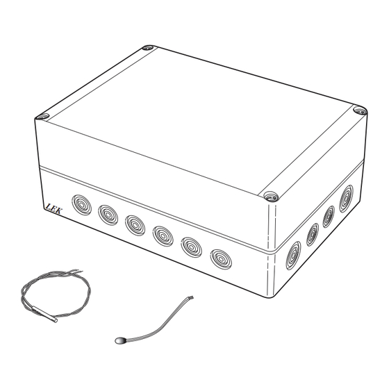
Pipe connections Charge pump Place the charge pump (GP4) on the return line to the solar panel according to the outline diagram. Temperature sensor Sensor, solar panel (BT53) is placed in the solar panel's submerged tube by the outlet from the solar panel. Sensor, solar coil (BT54) is positioned in submerged tube UA3 (VPBS). -
Page 4: Outline Diagram
QM54 - Shut-off valve, heating medium side QM57 QN10 Reversing valve, heating/hot water RM10 - Non-return valve RM13 EP30 SOLAR 42 Accessory card BT53 Sensor, solar panel BT54 Sensor, solar coil GP30 Pump station Safety valve, solar Circulation pump, solar... - Page 5 Outline diagram F1145 with VPBS and SOLAR 42 -EB100-BT1 -QM12 -FL2 -CM2 -CM1 -QM42 -QM31 -XL15 -FL3 -EB100 -QM34 -HQ1 -CP10 -QM32 -EB100 -EP30-BT53 -EP8 -EB100-BT6 -EP30 -BT54 -EP12 -EP30 -CM5 -GP30 -AA5 F1145 -RM4 -RM3 -FL4 -GP4 -QM44 -QM45...
-
Page 6: Electrical Connection
Electrical installation and wiring must be carried out in accordance with the stipulations in force. The heat pump must not be powered when in- stalling SOLAR 42. The electrical circuit diagram is at the end of this Installer handbook. Connecting the supply Connect the power supply to terminal block X1 as illus- trated. - Page 7 Connecting solar panel cooling Connect solar panel cooling (if applicable) to AA5-X9:3 (N) and AA5-X9:4 (230 V). -X10 Caution The relay outputs on the accessory card can have DIP switch a max load of 2 A (230 V) in total. The DIP switch on the accessory card must be set as fol- lows.
-
Page 8: Program Settings
Program settings Program setting of SOLAR 42 can be performed via the start guide or directly in the menu system. Caution Also see the Installer manual for F1145/F1345. Caution This accessory may require a program software update in your F1145/F1345.
Need help?
Do you have a question about the Solar 42 and is the answer not in the manual?
Questions and answers