
Related Manuals for Endress ESE 1408 DGB ES DIN


Summary of Contents for Endress ESE 1408 DGB ES DIN
- Page 1 OPERATING INSTRUCTIONS Power generators in accordance with DIN 14685-1 ESE 1408 DBG ES DIN Article No. 156519...
-
Page 2: Endress
E135351 Publication date May 2015 Copyright © 2015, ENDRESS Elektrogerätebau GmbH This documentation and parts thereof are subject to copy- right. Any use or modification beyond the restrictions of the Copyright Act is forbidden and subject to penalty without the consent of ENDRESS Elektrogerätebau GmbH. -
Page 3: Table Of Contents
Table of Contents Table of Contents ENDRESS ........................2 Elektrogerätebau GmbH .................... 2 E135351 ........................2 General information ..................9 Documentation ......................10 Safety symbols ......................11 Warning of a general hazard ................... 11 Warning of potentially explosive materials ............11 Warning of a dangerous electrical voltage ............ - Page 4 Table of Contents 2.3 Operating personnel - Qualifications and Obligations ..........18 2.4 Personal protective equipment ................18 2.5 Danger zones and work areas ................19 2.6 Signs on the generator ....................20 General safety warnings .................. 22 Notes......................... 26 Description of the generator 1408 DBG ES DIN ........... 27 3.1 Views of the generator...................
- Page 5 Table of Contents Start the engine as follows: ..................37 4.5 Switching the generator off ..................41 The device is switched off as follows: ..............41 4.6 Connecting up to consumers ................. 43 4.7 Check the protective conductor (valid for devices up to year of construction 12/2015) ......................
- Page 6 Table of Contents Disconnect the external start device as follows: ..........59 5.7 Battery charge retention device ................60 Disconnect the battery charge conservation device as follows: ......60 5.8 3-way fuel valve / Refuelling device ............... 62 Connect up fuelling device as follows: ..............63 Connect the canister to the fuelling device as follows: ........
- Page 7 Table of Contents 8 Technical specifications ..................76 9 Replacement parts ......................79 9.1 Sound-absorbing hood ..................79 9.2 Engine alternator and exhaust ................83 9.3 Generator ......................84 *Attention! Line circuit breaker with a characteristic specially adapted to the alternator. Do not use a line circuit breaker with a standard characteristic.
- Page 8 Table of Contents Table 4.4: Insulation monitoring whilst running without switching off ..............52 Table 4.5: Insulation monitoring plus switching off ....54 Table 4.6: Insulation monitoring whilst running without switching off ..............54 Table 4.7: Switchingpositions of the 3-way fuel tap ....62 Table 6.1: Location of the fuses .........71 Table 7.1: Difficulties operating the generator ....75 Table 8.1: Reference conditions Output of the generators .78...
-
Page 9: General Information
General information 1 General information These operating instructions must be read carefully and un- derstood before using the generator. These operating instructions are intended to familiarise you with the basic operation of the generator. These operating instructions contain important information on using the generator safely and appropriately. -
Page 10: Documentation
General information Documentation In addition to these operating instructions, the following doc- uments are relevant for the generator: Operating instructions and maintenance instructions for the engine (Briggs & Stratton Corporation) Circuit diagram for the generator Declaration of Conformity ... -
Page 11: Safety Symbols
General information Safety symbols The safety warning symbol indicates that a source of danger exists. The safety warning symbols used in the work area of the machine/plant and the entire technical documentation correspond to the EC Directive 2006/42 - Minimum require- ments for the provision of safety and/or health signs at work. -
Page 12: Notes
General information Notes ESE 1408 DBG ES DIN Status at: May 2015... -
Page 13: General Safety Regulations
Whoever operates the generator or works with it must read this chapter and comply with its regulations in practice. 2.1 Important safety warning ENDRESS generators are designed to operate electrical equipment with appropriate power output requirements. Oth- er applications can lead to injury to the operating personnel and to damage to the generator as well as other damage to equipment. -
Page 14: Intended Use
The following actions are not permitted. Operation in explosion-prone environments Operation in fire-prone environments Operation in confined areas Operation from a vehicle platform that has not been swung out Operation without the necessary safety redundancies ... -
Page 15: Residual Risks
The methods that will be used to install the generator on these vehicle platforms require written approval from the distributor that supplied the generator. The generator is not to be connected up to other energy dis- tribution systems (e.g. public power supply) or to other ener- gy generation systems (e.g. - Page 16 the specific warnings given in these operating instruc- tions the specific service instructions (for the respective oper- ating conditions) of BOS. Risk of death Risk of death to persons at the generator can be caused by: Incorrect use ...
- Page 17 Material damage to other Material damage to other equipment in the operating area of property the generator can be caused by: Inappropriate handling An overvoltage or an undervoltage Incorrect installation in a vehicle Limits to performance or The generator's performance or functionality can be limited functionality ...
-
Page 18: Operating Personnel - Qualifications And Obligations
2.3 Operating personnel - Qualifications and Obligations Only appropriately authorised personnel may work with or on the generator. The authorised operating personnel must: be of age. be trained in first aid and able to provide it. be familiar with the accident prevention regulations and generator safety instructions and be able to apply them. -
Page 19: Danger Zones And Work Areas
2.5 Danger zones and work areas The danger zones and work places (work areas) around the generator are determined by the activities to be undertaken within the individual life cycles: Life cycle Activity Danger zone Work area Transport in the vehicle Radius of 1.0 m none by the operating per-... -
Page 20: Signs On The Generator
2.6 Signs on the generator These signs must be fitted on the generator and be kept in a clearly legible condition: Figure 2-1: Signs on the generator Reference note - read operating in- Reference note - maintenance inter- structions vals Note EMERGENCY-STOP Potential equalisation screw (earthing Note re external refuelling... - Page 21 Sign Name Reference note - read operating instructions Note EMERGENCY- STOP Connection Potential equalization Earthing connection for the option with the TN-S system with RCD 30mA Generator model plate Reference note - maintenance intervals External refuelling Note hot surface Status at: May 2015 ESE 1408 DBG ES DIN...
-
Page 22: General Safety Warnings
Sign Name Fuel note Note Line extension Reference note - noise emission Table 2.2: Signs on the generator General safety warnings The generator's construction may not be modified in any way. The motor's nominal rpm has been set in the factory and may not be changed. - Page 23 Protect the generator against moisture and precipitation (rain, snow) during operation. Protect the generator against dirt and foreign matter during operation. The authorised personnel are responsible for the operational reliability of the generator. The authorised personnel are responsible for safeguarding the generator against unauthorised operation.
- Page 24 Setting up The generator is only be set up on sufficiently firm ground. The generator may only be set up on even ground. Generating electricity The electrical safety must be checked before each start-up. Do not cover the equipment during use. Do not obstruct or block the air supply.
- Page 25 Maintenance and repair Operating personnel may only carry out the maintenance or work repair work described in these operating instructions. All other maintenance or repair tasks may only be carried out by specially trained and authorised specialists. Before beginning the maintenance and/or repair work, al- ways pull out the spark plug connector and set the Start-Stop switch at the position Off (0) The maintenance intervals specified in these operating in-...
-
Page 26: Notes
Notes ESE 1408 DBG ES DIN Status at: May 2015... -
Page 27: Description Of The Generator 1408 Dbg Es Din
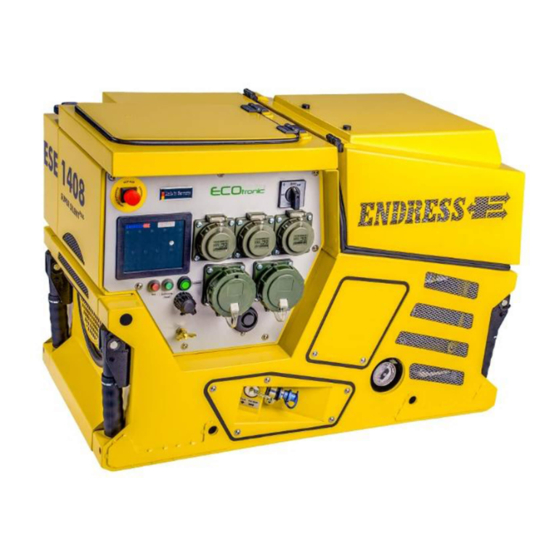
3 Description of the generator 1408 DBG ES DIN The components and functionality of the generator are de- scribed in this section. 3.1 Views of the generator The generator components are distributed on all four sides. The standard equipment is described here. Fig. -
Page 28: Operating And Engine Side Components
3.1.1 Operating and engine side components Figure 3-2: Components on the operating and engine side Engine side covering hood Control panel External refuelling connection Reversing starter (rope handle) Air filter Oil filter cover Electrical compartment Carrying handle Briggs & Stratton engine Fastening points according to DIN14685 ESE 1408 DBG ES DIN... -
Page 29: Exhaust And Generator Side Components
3.1.2 Exhaust and generator side components Figure 3-3: Components on the exhaust and generator side Exhaust side on the left (standard) Fastening points according to DIN 14685 Filler cap Battery compartment cover Carrying handle Status at: May 2015 ESE 1408 DBG ES DIN... -
Page 30: Control Panel Components
3.1.3 Control panel components Fig. 3-4: Control panel components Line circuit breaker Potential equalisation screw (earthing for an RCD) Line circuit breaker window Socket for protective earthing con- ductor test (valid for devices up to year of con- struction 12/2015) EMERGENCY-STOP switch START-STOP switch Multi-functional display... -
Page 31: Accessory Components
3.1.4 Accessory components Standard accessories Figure 3-5: Components of the standard accessories Spark plug wrench Test probes (valid for devices up to year of con- struction 12/2015) User information (operating instruc- Spark plugs (2x) tions for the engine, as well as these operating instructions) Testing cable (valid for devices up to year of con-... -
Page 32: Function And Operating Mode
Special accessories Fig. 3-6: Components of the special accessories Exhaust hose DN 50 – 1500 mm Fuelling device 20 litre standard container according to DIN 14572 3.2 Function and operating mode The synchronous generator is firmly coupled to the drive engine. -
Page 33: Notes
Notes Status at: May 2015 ESE 1408 DBG ES DIN... -
Page 34: Operation
4 Operation The operation of the generator is described in this section. 4.1 Transporting the generator Proceed as follows to transport the generator. Requirements The following requirements must be met: The generator must be turned off The generator must have cooled down. ... -
Page 35: Set Up The Generator As Follows
Requirements The following requirements must be met: An even and firm substratum outdoors There are no inflammable materials at the operating site There are no explosive materials at the operating site If necessary create the potential equalization using other electrically conductive parts, for example a vehicle. -
Page 36: Refuel The Generator As Follows
Requirements The following requirements must be met: switched off generator (see 4.5) The device must be cooled down. adequate supply and removal of air Appliances switched off or disconnected WARNING! Leaking engine oil and petrol can burn or explode! ... -
Page 37: Start The Engine As Follows
A possibly connected fuelling device (special accessory) sufficient oil level (fill with engine oil before initial use, see the engine operating and maintenance instructions) adequate supply and removal of air Fit push-on exhaust gas pipe (special accessory) if needed ... -
Page 38: Figure 4-1: Actuate Manual Choke
Figure 4-1: Actuate manual choke Figure 4-2: Standard design of operating panel ELECTRICAL START ESE 1408 DBG ES DIN Status at: May 2015... - Page 39 1. Pull on the manually-operated choke in < (Figure 4-1-(1)) (completely for a cold engine / appropriately less for a warm engine) and hold firmly. 2. Turn the START-STOP switch completely to (Figure 4-2-(2)) the right into the position “START” until the engine starts and then release.
-
Page 40: Fig. 4-3: Choke On The Engine Side
Fig. 4 3: Choke on the engine side Figure 4-4: Fuel pump for an emergency start ESE 1408 DBG ES DIN Status at: May 2015... -
Page 41: Switching The Generator Off
4.5 Switching the generator off Proceed as follows to shut down the generator. WARNING! Hot parts can ignite flammable and explosive materials. Avoid flammable materials at the operating site. Avoid explosive materials at the operating site. Allow the generator to cool down. Switching the device off The device is switched off as follows: Electrical start... - Page 42 Notes ESE 1408 DBG ES DIN Status at: May 2015...
-
Page 43: Connecting Up To Consumers
4.6 Connecting up to consumers Proceed as follows to connect appliances to the generator. Requirements The following requirements must be met: a started generator (see 4.4) protective earthing conductor test completed (see 4.7) device switched off WARNING! Electric shocks cause injury or death. -
Page 44: Check The Protective Conductor (Valid For Devices Up To Year Of Construction 12/2015)
4.7 Check the protective conductor (valid for devices up to year of construction 12/2015) Proceed as follows to check the protective conductor con- nection between the generator and the consumer. Requirements The following requirements must be met: a started generator (see 4.4) ... -
Page 45: Monitoring The Operating Status Using The Multifunction Display
4.8 Monitoring the operating status using the multifunction display All LEDs light up for about 2 seconds to allow checking as soon as the START-STOP switch is set to the position “Op- erate”. The normal operational lighting is then shown after- wards for about 30 seconds. - Page 46 Oil pressure: If the display lights up red whilst the gener- (see Figure 4-7-(15)) ator is running then the oil pressure is too low and the gen- erator switches automatically or the buzzer sounds, this can be acknowledged using the acknowledgement button. Engine temperature: If the display is red whilst the generator is...
- Page 47 The display gives a rough indication of the (see Figure 4-7-(10)) contents of tank. Symbol Display Significance Fuel tank filling level: green Fill level 100% green Fill level 100% green Fill level 90% green Fill level 70% green Fill level 60% green Fill level 40% Fill level below...
- Page 48 pressed. The buzzer can be acknowledged using the acknowledgement button. ESE 1408 DBG ES DIN Status at: May 2015...
-
Page 49: Putting The Generator Out Of Service
Observe all local laws and regulations concerning correct disposal of such parts and substances. Your author- ised ENDRESS generator dealer is happy to advise you. Please observe the pertinent environmental protection regu- lations when disposing of the old oil. We recommend bring- ing the oil in a closed container to an old oil collection centre for disposal. -
Page 50: Using Special Fittings / Accessories
5 Using special fittings / accessories 5.1 TN-S system with 30mA FI protection switch The 30mA FI protection switch option can only be supplied by the factory. The FI circuit breaker (RCD) is a protective measure against dangerous body currents according to DIN VDE 0100-551. Earthing requirements: 1. -
Page 51: Table 4.2: Fi Protection Switch Test
WARNING! The generator must be earthed. In this special case the generator must be earthed! The above-mentioned safety warnings with other wording are not relevant for this special fitting. Attention! 1. The effectiveness of this protective measure should be checked by an electrician. -
Page 52: Insulation Monitoring Using E-Mcs 4.0
5.2 Insulation monitoring using E-MCS 4.0 The insulation monitoring option can only be supplied by the factory. 5.2.1 Insulation monitoring without switching off (acc. to DIN 14685-1) Requirements The following requirements must be met: a started generator (see 4.4) Testing the insulation 1. - Page 53 If an insulation fault exists and the unit was previously OK when tested without a device connected (see insula- tion monitoring above), the insulation fault has been caused by the device. The reset button must be pressed after (see Fig.
-
Page 54: Insulation Monitoring With Switching Off(Optional, On When Requested By The Customer)
5.2.2 Insulation monitoring with switching off(Optional, on when requested by the customer) Requirements The following requirements must be met: Generator started Testing the insulation 1. Unplug the device monitoring: 2. The circuit breaker must be in Pos. 1. 3. Press the test button (see Fig. -
Page 55: Led Switch For Instrument Lighting
5.3 LED switch for instrument lighting Fig. 5-3: LED switch for instrument lighting Pressing the switch(Fig. 5-3-(2)) switches on the LED in- Switching on the der LED strument lighting. The LED lights up independently of the lighting operating condition of the generator, position of the START- STOP switch. -
Page 56: Speed Reduction At Idle
5.4 Speed reduction at idle Proceed as follows to operate the generator with idling speed reduction. Requirements The following requirements must be met: generator is ready for operation generator started Switching the idle down Fig. 5-5: Switching the idle down on pressure switch Switch on idle speed reduction as follows: pressure switch until it engages (LED... -
Page 57: Remote Start Device
5.5 Remote start device Proceed as follows to operate the generator using the re- mote start device. Requirements The following requirements must be met: generator is ready for operation WARNING! Devices with a remote start device are fitted with an auto- matic choke. -
Page 58: Disconnect The Remote Start Device As Follows
Disconnect the remote start device as follows: 1. Release the clip and then pull the remote start operating status / generator connecting cable plug out. Disconnecting the remote 2. Fold down the protective cap (if fitted) onto the remote start device start socket and lock in place using the clip. -
Page 59: External Start Device
5.6 External start device Proceed as follows to operate the generator using the exter- nal start device. Requirements The following requirements must be met: generator is ready for operation Connecting up an external start device Fig. 5-8: Connecting up an external start device Connect up the external start device as follows: 1. -
Page 60: Battery Charge Retention Device
5.7 Battery charge retention device Proceed as follows to charge the starter battery for the gen- erator over the battery charge retention device. Requirements The following requirements must be met: generator is ready for operation Connecting up the battery Connect up the battery charge conservation device charge conservation (charge current socket A DIN 14690) as follows:... - Page 61 The charge conservation device is disconnected Connecting up the battery Connect up the battery charge conservation device charge conservation (charge current socket BEOS) as follows: device Fig. 5-10: Connecting up the battery charge retention device 1. Unscrew cover for socket for the (Fig.
-
Page 62: 3-Way Fuel Valve / Refuelling Device
1. Put plug for the external energy source (e.g. a battery charging device) / charge retention device socket con- necting cable in place. The battery charge conservation device is ready to oper- ate. 5.8 3-way fuel valve / Refuelling device Proceed as follows to use the refuelling device with the gen- erator. -
Page 63: Connect Up Fuelling Device As Follows
The fuel supply is established. WARNING! Leaking engine oil and petrol can contaminate the soil and groundwater. Do not fill the canister completely. Allow the fuelling device to drain off. WARNING! Using the wrong fuel will destroy the engine. ... -
Page 64: Connect The Canister To The Fuelling Device As Follows
The fuelling device is disconnected from the generator. Connect up canister Connect the canister to the fuelling device as follows: 1. Open sealing cap on the canister. 2. Introduce hose. 3. Engage catch on the fuelling device. The canister is attached. Changing the canister Change an empty canister during operation as follows: during operation... -
Page 65: Exhaust Hose
5.9 Exhaust hose Proceed as follows to use the exhaust hose with the genera- tor. Requirements The following requirements must be met: Generator is ready for operation WARNING! Exhaust gases can cause fatal asphyxiation. Provide for sufficient ventilation. ... -
Page 66: Maintaining The Generator
6 Maintaining the generator Generator maintenance is described in this section. Only personnel from the manufacturer may carry out mainte- nance or repair work not described in this section. 6.1 Maintenance plan Only authorised personnel are allowed to carry out mainte- nance tasks. -
Page 67: Changing The Starter Battery
6.2.2 Changing the starter battery 1. Unscrew the battery holder. 2. Remove the battery from the battery compartment. 3. Unscrew the battery cable. Push the protective terminal caps back for this purpose and loosen the screws. Al- ways disconnect the cable from the NEGATIVE terminal first and then disconnect the cable from the POSITIVE terminal. -
Page 68: Engine Oil
The Endress battery is maintenance-free throughout its entire service life. See regulations for handling the bat- tery Never open the battery. 6.2.3 Engine oil WARNING! Leaking engine oil can contaminate soil and groundwa- ter. Use an oil collection container. -
Page 69: Pour In Oil As Follows
2. Reinsert the dipstick and take it out again. Drain off some of the oil if the level is above the upper mark and refill with oil if the level is under the lower mark (see below). The oil level has been checked. Refilling with oil Pour in oil as follows: 1. - Page 70 5. Tip the device slightly so that the oil can run off com- pletely 6. Then close the oil screw plug again and screw (Fig. 6-3-(3)) the side plate on again. 7. Then pour in new oil as already described. ...
-
Page 71: Replacing Fuses
6.2.4 Replacing fuses Replacing fuses (only for the special accessory external start socket, socket, charging retention and/or remote start de- vice) 1. Open the fuse holder. 2. Replace the fuse. 3. Close the fuse holder The fuse has been replaced. Fig. - Page 72 6.3 Checking the electrical safety/repeat checking Only specifically authorised personnel may check the electri- cal reliability. The electrical reliability must be checked in accordance with the applicable VDE regulations, EN and DIN standards and especially the current version of the BGV A3 accident pre- vention regulations.
-
Page 73: Troubleshooting
7 Troubleshooting This section describes problems during operation that au- thorized personnel can remove. Each occurring problem is described with its possible cause and the respective corrective measure. The authorised personnel must immediately shut down the generator and inform the responsible and authorised service personnel if a problem cannot be solved with the aid of the following table. - Page 74 Malfunction Possible cause Correction The battery connecting cables Clamp or screw on the battery are unclamped. connecting cables. Starter battery has no power. Battery is discharged. Charge battery. Battery is defective. Exchange battery. Battery terminals are oxi- Clean battery terminals and if dized.
-
Page 75: Table 7.1: Difficulties Operating The Generator
Malfunction Possible cause Correction The test tip is not touching a Hold the test tip on a metallic metallic blank location on the blank location device. Test lamp is defective Call service staff. The protective conductor is Disconnect the device from defective. -
Page 76: Technical Specifications
8 Technical specifications The technical specifications concerning use of the generator are described in this section. Fig. 8-1: Generator dimensions ESE 1408 DBG ES DIN Status at: May 2015... - Page 77 Technical specifications Name Value Unit Type 1408 DBG ES DIN Nominal output Sr/Pr (LPT) 13.7/10.9 [kVA]/[kW] Nominal output factor 3~ [cosφ] Nominal output factor 1~ [cosφ] Nominal frequency fr [Hz] Nominal speed nr 3000 [min Nominal voltage 3~ Ur Nominal voltage 1~ Ur Rated current 3~ Ir 19.8 Rated current 1~ Ir...
-
Page 78: Table 8.1: Reference Conditions Output Of The Generators
Ambient conditions Name Value Unit Setting up height above sea < 100 level Temperature < 25 [°C] Relative air humidity < 30 Table 8.1: Reference conditions Output of the generators Reduced power Power reduction for each addi- Unit tional [°C] Table 8.2: Generator power reduction dependent on ambient conditions Distribution network Line... -
Page 79: Replacement Parts
9 Replacement parts The replacement parts needed to run the generator are de- scribed in this section. The generator is divided into these component groups: Frame with covers, tank and engine Generator and electronics Standard accessories Special accessories ... - Page 80 Item Part number Quantity Item designation E135252 Sound-absorbing hood complete. RAL 3000 (in- cludes the whole frame) (color code 31) E135313 Sound-absorbing hood complete. RAL 3000 ver- sion Magirus (includes the whole frame) (color code 31) E135276 Sound-absorbing hood complete. RAL 5002 (in- cludes the whole frame) (color code 51) E135298 Sound-absorbing hood complete.
- Page 81 Item Part number Quantity Item designation E508688/69 E508934/11 E508934/31 G-cover E508934/51 E508934/62 E508934/71 E508934/69 E508697/11 E508697/31 E508697/51 G-E-box-02 E508697/62 E508697/71 E508697/69 E509043/11 E509043/69 G-R-wall-special E509043/69 E509043/69 E509043/69 E509043/69 E508668/11 E508668/31 G-L-side-01 E508668/51 E508668/62 E508668/71 E508668/69 E508679/11 E508679/31 G-L-side-03 E508679/51 E508679/62 E508679/71 E508679/69 E508669/11...
- Page 82 Item Part number Quantity Item designation E508921/51 G-sound-wall E508921/62 E508921/71 E508921/69 E508917/11 E508917/31 E508917/51 G-back-wall E508917/62 E508917/71 E508917/69 E509316/11 E509316/31 E509316/51 G-hood with logo - 01 E509316/62 E509316/71 E509316/69 140/1 E509352/31 G-hood-logo-MAGIRUS E508944/11 E508944/31 Plate-cover-04 E508944/51 E508944/62 E508944/71 E508944/69 E508905/11 E508905/31 G-Front wall E508905/51...
-
Page 83: Engine Alternator And Exhaust
9.2 Engine alternator and exhaust Fig. 9-2: Replacement parts for engine, alternator and exhaust Item Part number Quantity Item designation E131590 MotVan23HP/ES Cooler clean 692520 Air filter replacement 842921 Oil filter E133301 Vibration damper Form B 808624 Solenoid fuel Starter−rewind 841729 E133049 Alternator 13 kVA IP 54 50Hz... -
Page 84: Generator
9.3 Generator Fig. 9-3: Replacement parts Generator Item Article name ESE 1408 DBG ES DIN Status at: May 2015... - Page 85 Item Article name E133317 Three-way valve 38.343-60 E100776 Lock nipple with inside thread “Copper seal 12x16x1,5 E100616 E131017 Protective cap for hose nipple E133007 Schuko panel mounting socket outlet TM E130424 CEE panel mounting socket outlet TM E134171 Piezo siren RSP-5018 E131540 EMERGENCY-STOP switch E134413...
-
Page 86: Attention! Line Circuit Breaker With A Characteristic Specially Adapted To The Alternator
Item Article name E130388 MagCode PowerSystem 12 V E134413 Green pressure switch / lighting E131863 Muffler cushion E504507/92 Perforated plate D. 45 “Circlip 45 x 1,75 E131010 Tab.9.3: Replacement parts for generator *Attention! Line circuit breaker with a characteristic specially adapted to the alternator. -
Page 87: Accessories And Markings
9.4 Accessories and markings Fig. 9-4: Replacement parts for accessories Fig. 9-5: Replacement parts forspecial accessories Status at: May 2015 ESE 1408 DBG ES DIN... - Page 88 Item Part number Quantity Article name Champion 12YC spark plugs (no other type may E130472 be used) E130545 Test probes (valid for devices up to year of con- struction 12/2015) 100 cm measuring line E130446 (valid for devices up to year of construction 12/2015) Engine operating manual B&S E130534...
Need help?
Do you have a question about the ESE 1408 DGB ES DIN and is the answer not in the manual?
Questions and answers