
Related Manuals for Endress ESE 1306 HS-GT ES


Summary of Contents for Endress ESE 1306 HS-GT ES
- Page 1 OPERATING INSTRUCTIONS ESE 1306 HS-GT ES Article No. 230028A ESE 1306 DHS-GT ES Article No. 230029A ESE 1506 DHS-GT ES Article No. 230031A...
- Page 2 E134971 Publication date September 2013 Copyright © 2013, ENDRESS Elektrogerätebau GmbH This documentation and parts thereof are subject to copy- right. Any use or modification beyond the restrictions of the Copyright Act is forbidden and subject to penalty without the consent of ENDRESS Elektrogerätebau GmbH.
-
Page 3: Table Of Contents
Table of Contents Table of Contents General information ..................7 Further documents ..................... 8 Safety symbols ....................9 General Safety Regulations................11 Important safety warning .................. 11 Intended use ....................12 2.2.1 Residual risks .....................13 Operating personnel – qualifications and obligations ........16 Personal protective equipment ................. - Page 4 Table of Contents Maintenance work .................... 37 5.2.1 Charge battery ....................37 5.2.2 Replacing the starter battery ................37 5.2.3 Motor oil ......................39 Checking the electrical safety ................41 Troubleshooting ....................42 Technical specifications ................. 45 Replacement parts ..................49 Frame / alternator / motor ................49 ESE 1306 - 1506 Version: September 2013...
- Page 5 Table of Contents List of illustrations Fig. 3-1: Starting the motor ..........29 Fig. 3-2: Connecting up consumers/appliances ....31 Fig. 4-1: Remote start device with CAN plug ......34 Fig. 5-1: Replacing the battery ..........37 Fig. 5-2: Oil dipstick ............39 Fig. 7-1: Generator dimensions ..........45 Fig.
- Page 6 Table of Contents We reserve the right to make modifications in terms of ongoing technical development. These instructions do not include technical modifications that occurred after printing. ESE 1306 - 1506 Version: September 2013...
-
Page 7: General Information
General information 1 General information These operating instructions must be read carefully and un- derstood before using the generator. These operating instructions are intended to familiarise you with the basic operation of the generator. These operating instructions contain important information on using the generator safely and appropriately. -
Page 8: Further Documents
General information 1.1 Further documents In addition to these operating instructions, the following doc- uments are relevant for the generator: Operating manual and maintenance instructions for the engine Regulations for handling the battery Circuit diagram for the generator The operating manual and the maintenance instructions from the engine manufacturer are integral components of these instructions and must be observed. -
Page 9: Safety Symbols
General information 1.2 Safety symbols The safety symbol illustrates a source of danger. The safety symbols in the work area of the machine/plant and the entire technical documentation correspond to the Council Directive 92/58/EEC - Minimum requirements for the provision of safe- ty and/or health signs at work. - Page 10 General information Notes ESE 1306 - 1506 Version: September 2013...
-
Page 11: General Safety Regulations
Whoever operates the generator or works with it must read this chapter and comply with its regulations in practice. 2.1 Important safety warning ENDRESS generators are designed to operate electrical equipment with appropriate power output requirements. Oth- er applications can lead to injury to the operating personnel and to damage to the generator as well as other damage to equipment. -
Page 12: Intended Use
The following actions are not permitted. Operation in explosion-prone environments Operation in fire-prone environments Operation in confined areas Operation from a vehicle platform that has not been swung out Operation without the necessary safety redundancies ... -
Page 13: Residual Risks
The generator may not be connected to other energy distri- bution systems (e.g. public power supply) or to other energy generation systems (e.g. other generators). The generator may not be used in explosion-prone environ- ments. The generator may not be used in fire-prone environments. The generator must be operated according to the specifica- tions in the technical documentation. - Page 14 Incorrect use Inappropriate handling Missing protective equipment Defective or damaged electrical components Fuel vapours Engine exhaust Too large a distribution network configuration Risk of injury Risk of injury to persons at the generator can be caused by: ...
- Page 15 Limits to performance or The generator's performance or functionality can be limited functionality Inappropriate handling Inappropriate maintenance or repair work Unsuitable operating fluids An installation altitude greater than 100 metres above sea level An ambient temperature exceeding 25°C ...
-
Page 16: Operating Personnel - Qualifications And Obligations
2.3 Operating personnel – qualifications and obligations Only appropriately authorised personnel may work with or on the alternator. The authorised operating personnel must: be of age. be trained in first aid and able to provide it. be familiar with the accident prevention regulations and generator safety instructions and be able to apply them. -
Page 17: Danger Zones And Work Areas
2.5 Danger zones and work areas The danger zones work places (work areas) on the genera- tor are determined by the activities to be performed within the individual life cycles: Life cycle Activity Danger zone Work area Transport in the vehicle Radius of 1.0 m none by the operating per-... -
Page 18: Labels On The Generator
2.6 Labels on the generator These labels must be attached to the generator and be kept in a clearly legible condition: Label Designation Reference note - read operating instructions Potential equalization (earthing for FI) Model plate Maintenance interval for the engine Note on the hot sur- face Fuel note... -
Page 19: General Safety Instructions
2.7 General safety instructions The generator's construction may not be modified in any way. The motor's nominal rpm has been set in the factory and may not be changed. All protective covers must be at hand and functional. All labels on the generator must be in place and in a clearly legible condition. - Page 20 Open flames and light are prohibited in the generator's dan- ger zone. Consumption of alcohol, drugs, medications, or other mind- altering substances is prohibited. The authorised personnel must be familiar with the alternator components and their function and know how to use them. Transport The generator may only be transported after it has cooled down.
- Page 21 Do not operate the generator without a sound damper. It is prohibited to operate the generator without air filters and with an opened air filter cover. Refuelling It is prohibited to refill the fuel tank on the generator during operation. It is prohibited to refill the fuel tank on the generator when it is still hot.
- Page 22 Maintenance and repair Operating personnel may only carry out the maintenance or work repair work described in these operating instructions. All other maintenance or repair tasks may only be carried out by specially trained and authorised specialists. Always remove the ignition key and the spark plug sockets before beginning maintenance and/or repair work.
-
Page 23: Function And Mode Of Operation
2.8 Function and mode of operation The synchronous generator is firmly coupled to the drive motor. The assembly is installed in a stable frame and equipped with a flexible, low-vibration suspension. Splash-proof, shockproof and CEE sockets with a nominal voltage of 230V and/or 400V / 50 Hz supply the power. An integrated voltage regulator controls the voltage of the alternator in the nominal speed range of the alternator. - Page 24 Notes ESE 1306 - 1506 Version: September 2013...
-
Page 25: Operation
3 Operation The generator's operation is described in this section. 3.1 Transporting the generator Proceed as follows to transport the generator. Requirements The following requirements must be met: The alternator must be turned off The generator must have cooled down. ... -
Page 26: Setting Up The Generator
3.2 Setting up the generator Proceed as follows to set up the generator. Requirements The following requirements must be met: An even and firm substratum outdoors There are no inflammable materials at the place of work There are no explosive materials at the place of work WARNING! Leaking engine oil and petrol can contaminate the soil and groundwater. - Page 27 WARNING! Leaking engine oil and petrol can burn or explode! Prevent leaking of engine oil and petrol. Generator is switched off. Generator has cooled down. Avoid open flames and sparks. WARNING! Leaking engine oil can contaminate the soil and groundwater.
-
Page 28: Starting The Generator
3.4 Starting the generator Requirements The following requirements must be met: Checked and tested for electrical safety There must be fuel in the tank. Sufficient oil level (fill with engine oil before initial use, see the engine operating and maintenance instructions) ... -
Page 29: Fig. 3-1: Starting The Motor
Fig. 3-1: Starting the motor ELECTRICAL START 1. Pull on the manually-operated choke (com- (Fig. 3-1-(2)) pletely for a cold engine / appropriately less for a warm engine) and hold firmly. 2. Turn the START-STOP switch completely into (Fig. 3-1-(1)) the position "START“... -
Page 30: Switching The Generator Off
3.5 Switching the generator off Proceed as follows to shut down the generator. WARNING! Hot parts can ignite flammable and explosive materials. Avoid flammable materials at the work location. Avoid explosive materials at the work location. Allow the generator to cool down. Switching the device off The device is switched off as follows: Electrical start... -
Page 31: Connecting Up Consumers/Appliances
3.6 Connecting up consumers/appliances Proceed as follows to connect appliances to the generator. Requirements The following requirements must be met: generator started device switched off WARNING! Electric shocks cause injury or death. Do not earth the generator. ... -
Page 32: Putting The Alternator Out Of Service
Observe all local laws and regulations concerning correct disposal of such parts and substances. Your author- ised ENDRESS generator dealer is happy to advise you. Please observe the pertinent environmental protection regu- lations when disposing of the old oil. We recommend bring- ing the oil in a closed container to an old oil collection centre for disposal. - Page 33 Notes ESE 1306 - 1506 Status: September 2013...
-
Page 34: Special Fittings / Using Accessories
4 Special fittings / using accessories 4.1 Remote start device Proceed as follows to operate the generator using the re- mote start device. Requirements The following requirements must be met: generator is ready for operation WARNING! Devices with a remote start device are fitted with an automatic choke. - Page 35 1. Insert plug for the remote start operating status / genera- tor connecting cable into the remote start socket and lock in place by turning to the right. Remote start device is ready for use. Disconnecting the remote Disconnect the remote start device as follows: start device 1.
-
Page 36: Maintenance
5 Maintenance Maintenance of the alternator is described in this section. Only personnel from the manufacturer may carry out mainte- nance or repair work not described in this section. 5.1 Maintenance plan The maintenance work specified in this summary must be carried out after the indicated time intervals. -
Page 37: Maintenance Work
5.2 Maintenance work Only authorised personnel may carry out maintenance tasks. Carry out all maintenance tasks specified in the maintenance plan according to the specifications in the enclosed operating and maintenance instructions for the engine. These operat- ing and maintenance instructions of the engine manufacturer are an integral component of these operating instructions. - Page 38 Avoid sparks when handling cables and electrical devic- es, as well as electrostatic discharge. Avoid short-circuits. WARNING! The Endress battery is maintenance-free throughout its entire service life. Never open the battery — this may destroy it. ESE 1306 - 1506...
-
Page 39: Motor Oil
5.2.3 Motor oil WARNING! Leaking motor oil can contaminate soil and groundwa- ter. Use an oil collection container. Recycle used motor oil. WARNING! Motor oil can be hot — risk of burns. Allow motor to cool. Requirements The following requirements must be met: ... - Page 40 1. Remove oil screw plug . Pull out the dipstick (Fig. 5-2-(1)) for easier filling ( (Fig. 5-2-(2)) 2. Fill with oil using a filling aid. 3. Check oil level and add oil if necessary. The engine has been refilled with oil. WARNING! The oil escapes immediately after unscrewing the oil drainage screw.
-
Page 41: Checking The Electrical Safety
5.3 Checking the electrical safety Only appropriately authorised personnel may check the elec- trical reliability. The electrical reliability must be checked in accordance with the applicable VDE regulations, EN and DIN standards and especially the current version of the BGV A3 accident pre- vention regulations. -
Page 42: Troubleshooting
6 Troubleshooting This section describes problems during operation that au- thorized personnel can remove. Each occurring problem is described with its possible cause and the respective corrective measure. The authorised personnel must immediately shut down the generator and inform the responsible and authorised service personnel if a problem cannot be solved with the aid of the following table. - Page 43 Malfunction Possible cause Correction Battery terminals are oxi- Clean battery terminals and if dized. necessary apply terminal grease. Starter battery is not being Alternator / charge regulator Call service staff. charged. defective. The engine does not rotate. Engine defective. Call service staff. The engine smokes.
- Page 44 Notes ESE 1306 - 1506 Version: September 2013...
-
Page 45: Technical Specifications
7 Technical specifications The technical specifications concerning use of the generator are described in this section. Fig. 7-1: Generator dimensions ESE 1306 - 1506 Status: September 2013... - Page 46 Technical specifications Bezeichnung Wert Einheit ESE 1306 HS- ESE 1306 DHS- ESE 1506 DHS- GT ES GT ES GT ES Nominal output 12,0 13,2 [kVA] Nominal power factor [cosφ] Nominal power factor [cosφ] Nominal frequency [Hz] Nominal speed 3000 [min Nominal voltage 3~ Nominal voltage 1~ Rated current 3~...
- Page 47 Ambient conditions Designation Value Unit Setting up height above sea < 100 level Temperature < 25 [°C] Relative air humidity < 30 Table 7.1: Ambient conditions for the generator Reduced output Output reduction for each addi- Unit tional [°C] Table 7.2: Generator performance reduction dependent on the ambient conditions Distribution network Line...
- Page 48 Notes ESE 1306 - 1506 Version: September 2013...
-
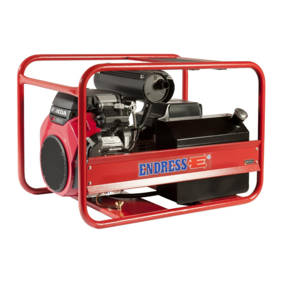
Page 49: Replacement Parts
8 Replacement parts The replacement parts needed to run the generator are de- scribed in this section. 8.1 Frame / alternator / motor Fig. 8-1: Frame / alternator / motor Item Part number Quantity Item designation E508518/31 Frame ESE 1006-1506 E134960 Motor GX630RH-VE-P4-OH (ESE 1306 HS) E134960... -
Page 50: Table 8.1: Replacement Parts For The Frame With Covers
Item Part number Quantity Item designation E134968 Generator E1C11M b 10 Kva (ESE 1306 HS) E134957 Generator E1S11M B 13,5KVA (ESE 1306 DHS) E134969 Generator E1S13S C/2 16KVA (ESE 1506 DHS) E504345/91 Tank Table 8.1: Replacement parts for the frame with covers ESE 1306 - 1506 Version: September 2013...
Need help?
Do you have a question about the ESE 1306 HS-GT ES and is the answer not in the manual?
Questions and answers