Sign In
Upload
Download
Table of Contents
Contents
Add to my manuals
Delete from my manuals
Share
URL of this page:
HTML Link:
Bookmark this page
Add
Manual will be automatically added to "My Manuals"
Print this page
×
Bookmark added
×
Added to my manuals
Manuals
Brands
Endress Manuals
Portable Generator
ESE 807 DBG DIN
Operating instructions manual
Endress ESE 807 DBG DIN Operating Instructions Manual
Hide thumbs
1
2
Table Of Contents
3
4
5
6
7
8
9
10
11
12
13
14
15
16
17
18
19
20
21
22
23
24
25
26
27
28
29
30
31
32
33
34
35
36
37
38
39
40
41
42
43
44
45
46
47
48
49
50
51
52
53
54
55
56
57
58
59
60
61
62
63
64
65
66
67
68
69
70
71
72
73
74
75
76
77
page
of
77
Go
/
77
Contents
Table of Contents
Troubleshooting
Bookmarks
Table of Contents
Table of Contents
1 General Information
Documentation and Accessories
Safety Symbols
2 General Safety Regulations
Important Safety Warning
Intended Use
Residual Risks
Operating Personnel - Qualifications and Obligations
Personal Protective Equipment
Danger Zones and Work Areas
Table 2.1: Danger Zones and Work Areas on the Generator
Signs on the Generator
Fig. 2-1: Signs on the Generator
Table 2.2: Signs on the Generator
General Safety Instructions
3 Description of the Generator ESE 807 - 1407 DBG (ES) DIN
Views of the Generator
Fig. 3-1: Views of the Generator
Components on the Operating and Engine Side
Fig. 3-2: Components on the Operating and Engine Side
Components on the Exhaust and Generator Side
Fig. 3-3: Components on the Exhaust and Generator Side
Control Panel Components
Fig. 3-4: Control Panel Components
Accessory Components
Fig. 3-5: Components of the Standard Accessories
Fig. 3-6: Components of the Special Accessories
Function and Mode of Operation
4 Operating ESE 807 - 1407 DBG (ES) DIN
Transporting the Generator
Setting up the Generator
Refuelling the Generator
Starting the Generator
Fig. 4-1: Actuate Manual Choke
Fig. 4-2: Standard Design of Operating Panel
Switching the Generator off
Connecting up to Consumers
Fig. 4-3: Connecting up to Consumers
Check the Protective Conductor
Fig. 4-4: Check the Protective Conductor
Table 4.1: Protective Conductor Test Lamp
Monitoring the Operating Status Using the Multifunction Display
Fig. 4-5: Multi-Functional Display
Putting the Generator out of Service
Disposal
5 Special Fittings / Using Accessories
FI Protection Switch
Fig. 5-1: FI Protection Switch
Table 5.1: FI Protection Switch Test
Insulation Monitoring Using E-MCS 4.0 (Without Switching Off)
Table 5.2: Insulation Monitoring Without Switching off
Table 5.3: Insulation Monitoring Whilst Running Without Switching off
Speed Lowering in Idle
Remote Start Device
Fig. 5-5: Remote Start Device with CAN Plug
External Start Device
Battery Charge Retention
Fig. 5-8: Connecting up the Battery Charge Retention Device
3-Way Fuel Valve / Refuelling Device
Table 5.4: Switchingpositions of the 3-Way Fuel Tap
Exhaust Hose
6 Maintain Generator ESE 807 - 1407 DBG (ES) DIN
Maintenance Plan
Maintenance Work
Table 6.1: Generator Maintenance Plan
Motor Oil
Fig. 6-2: Change the Oil
Replacing the Starter Battery
Replacing Fuses
Table 6.2: Location of the Fuses
Checking the Electrical Safety
7 Troubleshooting
Table 7.1: Problems Arising During Generator Operation
8 Technical Specifications
Table 8.1: Ambient Conditions for the Generator
Table 8.2: Generator Power Reduction Dependent on Ambient Conditions
Table 8.3: Maximum Line Length of the Distribution Network as a Function of the Cable Cross-Section
Status At: February 2013 ESE 807 / 1107 / 1307 / 1407 DBG (ES) DIN
Advertisement
Quick Links
Download this manual
OPERATING INSTRUCTIONS
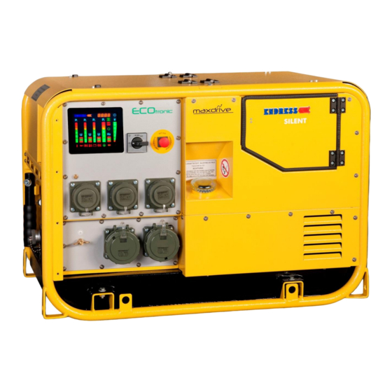
ESE 807 DBG DIN
ESE 807 DBG ES DIN
ESE 1107 DBG DIN
ESE 1307 DBG DIN
ESE 1407 DBG DIN
Article No. 151203 / 156203
Article No. 151213 / 156213
Article No. 151215 / 156215
Article No. 151216 / 156216
Article No. 151219 / 156219
Table of
Contents
Previous
Page
Next
Page
1
2
3
4
5
Advertisement
Table of Contents
Need help?
Do you have a question about the ESE 807 DBG DIN and is the answer not in the manual?
Ask a question
Questions and answers
Related Manuals for Endress ESE 807 DBG DIN
Portable Generator Endress ESE 808 DBG ES DUPLEX SILENT Operating Instructions Manual
(88 pages)
Portable Generator Endress ESE Series Translation Of The Operating Instructions
Power generator (452 pages)
Portable Generator Endress ESE Series Translation Of The Original Operating Manual
(76 pages)
Portable Generator Endress ESE 206 HS-GT Operating Instructions Manual
(530 pages)
Portable Generator Endress ESE 904 DBG DIN Operating Instructions Manual
(88 pages)
Portable Generator Endress ESE 1308 DBG ES DUPLEX SILENT Operating Instructions Manual
(88 pages)
Portable Generator Endress ECO Power Line ESE 3000 BS Translation Of The Original Operating Manual
(60 pages)
Portable Generator Endress ESE 954 DBG DIN Operating Instructions Manual
(91 pages)
Portable Generator Endress ESE 1008 LG ES DIESEL DUPLEX SILENT User Manual
(57 pages)
Portable Generator Endress ESE 2300 i Translation Of The Original Operating Manual
(60 pages)
Portable Generator Endress ESE Translation Of The Original Operating Manual
Power generator (60 pages)
Portable Generator Endress ESE 3200 P Operating Manual
Power generators (37 pages)
Portable Generator Endress ESE 1408 Translation Of The Original Operating Manual
(94 pages)
Portable Generator Endress ESE 67 IW Translation Of The Original Operating Manual
(78 pages)
Portable Generator Endress ESE 67 RS Translation Of The Original Operating Manual
(78 pages)
Portable Generator Endress ESE 90 IW Translation Of The Original Operating Manual
(78 pages)
This manual is also suitable for:
Ese 1307 dbg din
Ese 1407 dbg din
Ese 807 dbg es din
Ese 1107 dbg din
Table of Contents
Print
Rename the bookmark
Delete bookmark?
Delete from my manuals?
Login
Sign In
OR
Sign in with Facebook
Sign in with Google
Upload manual
Upload from disk
Upload from URL


Need help?
Do you have a question about the ESE 807 DBG DIN and is the answer not in the manual?
Questions and answers