
Related Manuals for Beckhoff KL5051


Summary of Contents for Beckhoff KL5051
- Page 1 Documentation KL5051 Bidirectional SSI encoder interface Version: Date: 2018-05-29...
-
Page 3: Table Of Contents
Connection system...................... 16 3.4.2 Wiring .......................... 18 3.4.3 Shielding .......................... 19 KL5051 - Connection and LED description................... 20 ATEX - Special conditions (standard temperature range) ............ 21 ATEX Documentation ........................ 22 4 Configuration Software KS2000...................... 23 KS2000 - Introduction ........................ 23 5 Access from the user program ...................... 25 KL5051 - Terminal configuration.................... - Page 4 Table of content Version: 3.0 KL5051...
-
Page 5: Foreword
The TwinCAT Technology is covered, including but not limited to the following patent applications and patents: EP0851348, US6167425 with corresponding applications or registrations in various other countries. ® EtherCAT is registered trademark and patented technology, licensed by Beckhoff Automation GmbH, Germany Copyright © Beckhoff Automation GmbH & Co. KG, Germany. -
Page 6: Safety Instructions
All the components are supplied in particular hardware and software configurations appropriate for the application. Modifications to hardware or software configurations other than those described in the documentation are not permitted, and nullify the liability of Beckhoff Automation GmbH & Co. KG. Personnel qualification This description is only intended for trained specialists in control, automation and drive engineering who are familiar with the applicable national standards. -
Page 7: Documentation Issue Status
• Chapters KS2000 configuration software and Access from the user program added Firmware (FW) and hardware (HW) versions Documentation, KL5051 version The firmware and hardware versions (delivery state) of the terminal can be found in the serial number printed on the side. -
Page 8: Product Overview
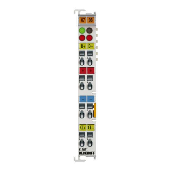
KL5051 - Introduction Fig. 1: KL5051 The KL5051 bidirectional SSI interface terminal enables the connection of digital servo drives. The encoder is powered via the SSI interface, which consists of two logic channels. The first channel is used for the positioning of the drive, while the second channel is used to set releases, to transmit parameter data and to read status information and parameter values. -
Page 9: Kl5051 - Technical Data
Product overview KL5051 - Technical data Technical data KL5051 Encoder connection Binary input: D+, D-; binary output: Cl+, Cl- Power supply 5 V via power contacts (KL9505) Current consumption Typically 85 mA without encoder Encoder supply 5 V Current consumption K-bus typically 75 mA Data transfer rate 1 MHz... -
Page 10: Basic Function Principles
Product overview Basic function principles The KL5051 bidirectional SSI interface terminal is used to connect the digital servo drive digifas®7100/7200 from Seidel to the Bus Coupler or controller. The interface consists of two logical channels: • The drive is positioned via the first channel, •... - Page 11 Product overview Process data The KL5051 is mapped with 6 bytes of input data and 6 bytes of output data. • A0, A1, A2 and E0, E1, E2 form the channel for setting and logging the operating data of the servo. • A3, A4, A5 and E3, E4, E5 form the channel for logging the servo status and for setting the servo control.
-
Page 12: Mounting And Wiring
Each assembly must be terminated at the right hand end with an EL9011 bus end cap, to ensure the protection class and ESD protection. Fig. 2: Spring contacts of the Beckhoff I/O components Installation on mounting rails Risk of electric shock and damage of device! -
Page 13: Fig. 3 Attaching On Mounting Rail
Note flict with the fixing bolts of the mounting rail. To mount the mounting rails with a height of 7.5 mm under the terminals and couplers, you should use flat mounting connections (e.g. countersunk screws or blind rivets). KL5051 Version: 3.0... -
Page 14: Fig. 4 Disassembling Of Terminal
PE power contact The power contact labeled PE can be used as a protective earth. For safety reasons this contact mates first when plugging together, and can ground short-circuit currents of up to 125 A. Version: 3.0 KL5051... -
Page 15: Fig. 5 Power Contact On Left Side
Power Feed Terminals can be released and pulled at least 10 mm from the group of terminals. Risk of electric shock! The PE power contact must not be used for other potentials! WARNING KL5051 Version: 3.0... -
Page 16: Installation Instructions For Enhanced Mechanical Load Capacity
• The terminals of ELxxxx and KLxxxx series with standard wiring include electronics and connection level in a single enclosure. • The terminals of ESxxxx and KSxxxx series feature a pluggable connection level and enable steady wiring while replacing. Version: 3.0 KL5051... -
Page 17: Fig. 6 Standard Wiring
The overview and nomenclature of the product names for ESxxxx and KSxxxx series has been retained as known from ELxxxx and KLxxxx series. High Density Terminals (HD Terminals) Fig. 8: High Density Terminals KL5051 Version: 3.0... -
Page 18: Wiring
Do not turn the screwdriver or move it alternately (don't toggle). 2. The wire can now be inserted into the round terminal opening without any force. 3. The terminal point closes automatically when the pressure is released, holding the wire securely and permanently. Version: 3.0 KL5051... -
Page 19: Shielding
Wire size width (conductors with a wire end sleeve) 0.14 ... 0.75 mm Wire size width (ultrasonically “bonded" conductors) only 1.5 mm Wire stripping length 8 ... 9 mm 3.4.3 Shielding Shielding Encoder, analog sensors and actors should always be connected with shielded, twisted paired wires. Note KL5051 Version: 3.0... -
Page 20: Kl5051 - Connection And Led Description
Mounting and wiring KL5051 - Connection and LED description Risk of injury through electric shock and damage to the device! Bring the Bus Terminals system into a safe, de-energized state before starting mounting, disassembly or wiring of the Bus Terminals! WARNING Fig. 10: KL5051 - Connection and LEDs... -
Page 21: Atex - Special Conditions (Standard Temperature Range)
• EN 60079-0:2012+A11:2013 • EN 60079-15:2010 Marking The Beckhoff fieldbus components with standard temperature range certified for potentially explosive areas bear one of the following markings: II 3G KEMA 10ATEX0075 X Ex nA IIC T4 Gc Ta: 0 … 55°C II 3G KEMA 10ATEX0075 X Ex nC IIC T4 Gc Ta: 0 … 55°C KL5051 Version: 3.0... -
Page 22: Atex Documentation
Notes about operation of the Beckhoff terminal systems in potentially explo- sive areas (ATEX) Pay also attention to the continuative documentation Note Notes about operation of the Beckhoff terminal systems in potentially explosive areas (ATEX) that is available in the download area of the Beckhoff homepage http:\\www.beckhoff.com! Version: 3.0... -
Page 23: Configuration Software Ks2000
Fieldbus Box modules with the aid of which settings can be modified easily. Alternatively, you have full access to all internal registers of the bus couplers and intelligent terminals. Refer to the register description for the meanings of the registers. KL5051 Version: 3.0... - Page 24 • Process values can be specified in the output image for commissioning of the output modules. All possibilities in the online mode can be used in parallel with the actual fieldbus mode of the terminal station. The fieldbus protocol always has the higher priority in this case. Version: 3.0 KL5051...
-
Page 25: Access From The User Program
Fig. 12: Mapping in the Lightbus Coupler – example for KL5051 BK3000 Profibus Coupler In the case of the Profibus coupler BK3000, the KL5051 is always mapped with 6 bytes of input and 6 bytes of output data. Fig. 13: Mapping in the Profibus Coupler – example for KL5051 KL5051 Version: 3.0... -
Page 26: Fig. 14 Mapping In The Interbus Coupler - Example For Kl5051
Access from the user program BK4000 Interbus Coupler By default, the Interbus coupler BK4000 maps KL5051 with 6 bytes of input and 6 bytes of output data. Fig. 14: Mapping in the Interbus Coupler – example for KL5051 Other Bus Couplers and further information Further information about the mapping configuration of Bus Couplers can be found in the Appendix of the respective Bus Coupler manual under Master configuration. -
Page 27: Mapping In The Bus Coupler
The following tables provide information about how the terminals map themselves in the Bus Coupler, depending on the parameters set. The KL5051 is mapped into the bus coupler depending on the set parameters. The KL5051 is mapped with 6 bytes of input data and 6 bytes of output data. -
Page 28: Register Overview
• R9: Software version (X.y) The software version can be read as a string of ASCII characters. • R10: Data length R10 contains the number of multiplexed shift registers and their length in bits. The Bus Coupler sees this structure. Version: 3.0 KL5051... - Page 29 This register specifies the operation modes of the terminal. Thus, for instance, a user-specific scaling can be activated for the analog I/Os. • R33 - R47 Registers that depend on the terminal type. • R47 - R63 Extended registers with additional functions. KL5051 Version: 3.0...
-
Page 30: Register Communication
Example 1: Reading of register 8 in the BK2000 with a KL5051 and the end terminal: If the following bytes are transferred from the controller to the terminal, Version: 3.0... -
Page 31: Data Exchange, Function
Faulty telegrams occur during data transmission (possibly EMC issue). Parameter control byte A3 when the servo control is set (bit 7 = 0) Various actions are performed in the servo drive with this control byte. REG=0 RD_PARH RD_PARL RS_ANS /NSTOP /PSTOP KL5051 Version: 3.0... - Page 32 The output stage and any existing brake are enabled. /NSTOP_Q 1: Negative set values are possible. (active low) 0: Negative set values are set to zero. /PSTOP 1: Positive set values are possible. (active low) 0: Positive set values are set to zero. Version: 3.0 KL5051...
-
Page 33: Examples Of Register Communication
The numbering of the bytes in the examples corresponds to the display without word alignment. 5.7.1 Example 1: reading the firmware version from Register 9 Output Data Byte 0: Control byte Byte 1: DataOUT1, high byte Byte 2: DataOUT1, low byte 0x89 (1000 1001 0xXX 0xXX Explanation: KL5051 Version: 3.0... -
Page 34: Example 2: Writing To An User Register
• The terminal returns a value as a receipt in the status byte that differs only in bit 0.6 from the value of the control byte. • The input data word (byte 1 and byte 2) is of no importance after the write access. Any values still displayed are invalid! Version: 3.0 KL5051... - Page 35 • The terminal returns a value as a receipt in the status byte that differs only in bit 0.6 from the value of the control byte. • The input data word (byte 1 and byte 2) is of no importance after the write access. Any values still displayed are invalid! KL5051 Version: 3.0...
- Page 36 • The terminal returns a value as a receipt in the status byte that differs only in bit 0.6 from the value of the control byte. • The input data word (byte 1 and byte 2) is of no importance after the write access. Any values still displayed are invalid! Version: 3.0 KL5051...
-
Page 37: Appendix
Beckhoff's branch offices and representatives Please contact your Beckhoff branch office or representative for local support and service on Beckhoff products! The addresses of Beckhoff's branch offices and representatives round the world can be found on her internet pages: http://www.beckhoff.com You will also find further documentation for Beckhoff components there. - Page 38 KS2000 configuration software....................Fig. 12 Mapping in the Lightbus Coupler – example for KL5051............. Fig. 13 Mapping in the Profibus Coupler – example for KL5051 ............. Fig. 14 Mapping in the Interbus Coupler – example for KL5051 ............. Fig. 15 Register mode control byte......................
Need help?
Do you have a question about the KL5051 and is the answer not in the manual?
Questions and answers