
Related Manuals for IEI Technology ROCKY-4783EV Series


Summary of Contents for IEI Technology ROCKY-4783EV Series
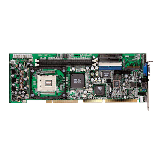
- Page 1 ROCKY – 4783EV Series SOCKET 478 PENTIUM 4 with LAN & USB 2.0 & IEEE-1394 AGP4X VGA SBC User Manual Version 1.1 June 18, 2003 ©Copyright 2003 by ICP Electronics Inc. All Rights Reserved.
- Page 2 Copyright Notice The information in this document is subject to change without prior notice in order to improve reliability, design and function and does not represent a commitment on the part of the manufacturer. In no event will the manufacturer be liable for direct, indirect, special, incidental, or consequential damages arising out of the use or inability to use the product or documentation, even if advised of the possibility of such damages.
-
Page 3: Table Of Contents
Table of Contents 1. Introduction ............... 4 Specifications ................5 Package Contents................7 2. Installation ..............8 ROCKY–4783EV Layout ..............8 Unpacking Precautions ..............9 Clear CMOS Settings..............10 Onboard Keyboard/Mouse source Setting........10 CompactFlash Master/Slave Setting ..........10 3. Connection ..............11 Floppy Disk Drive Connector ............12 PCI E-IDE Disk Drive Connector .......... -
Page 4: Introduction
Introduction Thank you for choosing ROCKY-4783EV SOCKET 478 PENTIUM 4 Single Board Computer. ROCKY-4783EV board is an ISA/PCI form factor board, which is equipped with a high performance processor and multi-mode I/O, designed for the system manufacturers, integrators, or VARs to provide quality and reliable performance at a reasonable price. -
Page 5: Specifications
Specifications Intel Pentium 4 Processor, supports 400/533 CPU (PGA 478) MHz FSB (FSB SETTING BY BIOS) Bus interface PCI/ISA bus, PICMG compliant Bus speed ISA: 8MHz, PCI: 33MHz DMA channels Interrupt levels 15 Chipset SIS 651 Real-time SIS 962 clock/calendar Two 184-pin DIMM sockets to support RAM memory DDR266/333 SDRAM. - Page 6 Built-in SiS 315 AGP4X 256-bit 3D graphics engine. 4~64 MB share memory. VGA controller Screen resolution: up to 2048 x 1536 x 16. Fast Ethernet controllers, IEEE 802.3u Auto- Negotiation support for 10BASE-T/100BASE-TX Ethernet standard. The RJ45 connectors are located on the mounting bracket for easy connection.
-
Page 7: Package Contents
Package Contents ROCKY-4783EV package includes the following items: • ROCKY-4783EV Single Board Computer x 1 • RS-232 and printer cable with bracket x 1 • FDD cable x 1 • ATA IDE cable x 1 • ATX-12V cable x 1 •... -
Page 8: Installation
Installation This chapter describes how to install ROCKY-4783EV. All shaded rows in tables of this manual are the default settings for ROCKY-4783EV. ROCKY–4783EV Layout... -
Page 9: Unpacking Precautions
Unpacking Precautions Some components on ROCKY-4783EV SBC are very sensitive to static electric charges and can be damaged by a sudden rush of power. To protect it from unintended damage, be sure to follow these precautions: Ground yourself to remove any static charge before touching your ROCKY-4783EV SBC. -
Page 10: Clear Cmos Settings
Clear CMOS Settings If want to clear the CMOS settings, close the JP10 (1-2) about 3 seconds, then open it again. This will set CMOS to normal operation mode, i.e. JP10 (2-3). • JP10: Clear CMOS Settings (Reserved Function) JP10 Description Clear CMOS Settings Normal Operation... -
Page 11: Connection
Connection This chapter describes how to connect peripherals, switches and indicators to the ROCKY- 4783EV board. Table of Connectors LABEL FUNCTION FAN1~FAN2 Fan Connectors ATX1 ATX 20-PIN Power Connector ATX2 ATX-12V CPU Power Source VGA 15-pin Female Connector IrDA connector ATX BUTTON (Power ON) Switch CN1, CN4, CN23 USB Connectors... -
Page 12: Floppy Disk Drive Connector
Floppy Disk Drive Connector The ROCKY-4783EV board is equipped with a 34-pin daisy-chain drive connector cable. • FDD1: FDC Connector Description Description GROUND REDUCE WRITE GROUND GROUND GROUND INDEX# GROUND MOTOR ENABLE A# GROUND DRIVE SELECT B# GROUND DRIVE SELECT A# GROUND MOTOR ENABLE B# GROUND... -
Page 13: Pci E-Ide Disk Drive Connector
PCI E-IDE Disk Drive Connector You can attach four IDE (Integrated Device Electronics) hard disk drives on two channels. These connectors support Ultra-DMA100 IDE devices. Non-DMA100 devices are suggested to be connecting to the secondary IDE connector. IDE 1: Primary IDE Connector IDE 2: Secondary IDE Connector •... -
Page 14: Parallel Port
Parallel Port This port is usually connected to a printer. The ROCKY-4783EV includes an on-board parallel port, accessed through a 26-pin flat- cable connector. • LPT1: Parallel Port Connector Description Description STROBE# DATA 0 DATA 1 DATA 2 DATA 3 DATA 4 DATA 5 DATA 6... -
Page 15: Serial Ports
Serial Ports ROCKY-4783EV offers two high speeds NS16C550 compatible UART. • COM1: 10-pin header on board • COM2: 10-pin header on board Connector Address Interrupt COM1 IRQ4 COM2 IRQ3 • Serial Port 10-pin Connector Description DATA CARRIER DETECT (DCD) RECEIVE DATA (RXD) TRANSMIT DATA (TXD) DATA TERMINAL READY (DTR) GROUND (GND) -
Page 16: Keyboard & Ps/2 Mouse Connector
Keyboard & PS/2 Mouse Connector A 6-pin mini DIN connector (CN19) is located on the mounting bracket for easy connection to a keyboard or a PS/2 mouse. The card comes with a cable to convert from the 6-pin mini-DIN connector to two 6-pin mini-DIN connectors for keyboard and mouse connection. -
Page 17: External Switches And Indicators
External Switches and Indicators There are several external switches and indicators for monitoring and controlling your CPU board. • CN2: External Switches and Indicators Description Description Speaker + Power Speaker Speaker - Reset Reset PIN1 Button Reset PIN2 HDD LED HDD LED+ HDD LED- HDD LED... -
Page 18: Irda Infrared Interface Port
IrDA Infrared Interface Port ROCKY-4783EV has a built-in IrDA port which supports Serial Infrared (SIR) or Amplitude Shift Keyed IR (ASKIR) interface. If you want to use the IrDA port, you have to configure SIR or ASKIR model in the BIOS under Peripheral Setup COM2. Then the normal RS-232 COM 2 will be disabled. -
Page 19: Lan Rj45& State Led Connectors
3.10 LAN RJ45& State LED Connectors ROCKY-4783EV is equipped with one built-in 10/100Mbps Ethernet controllers. You can connect it to your LAN through RJ45 LAN connectors. There are two LEDs on the connector (CN14) indicating the LAN status. • LAN1 RJ45 Connector Description Description •... -
Page 20: Audio Headphone & Connector
3.12 AUDIO Headphone & Connector ROCKY-4783EV has a built-in AC’97 AUDIO CODEC; connector directly connected to your MIC-IN & CD-IN & LINE-IN. • CN9: AUDIO CD-IN Connector (Input) • CN10: AUDIO MIC-IN Connector (Input) • CN11: AUDIO LINE-IN Connector (Input) •... -
Page 21: Ieee 1394 Port Connector
3.14 IEEE 1394 Port Connector ROCKY-4783EV provides three built-in IEEE 1394 ports to connect to 1394 devices. CN16 /CN17/CN18 Description Description +12V TPA- TPA+ TPB- SHIELD TPB+ SHIELD... -
Page 22: Ami Bios Setup
AMI BIOS SETUP 4.1 Introduction This chapter discusses AMI's Setup program built into the ROM BIOS. The Setup program allows users to modify the basic system configuration. This special information is then stored in battery- backed RAM so that it retains the Setup information when the power is turned off. -
Page 23: Using Setup
4.3 Using Setup In general, you use the arrow keys to highlight items, press <Enter> to select, use the PageUp and PageDown keys to change entries. Press <F1> for help and press <Esc> to quit. The following table provides more detail about how to navigate in the Setup program using the keyboard. -
Page 24: Getting Help
4.4 Getting Help Press F1 to pop up a small help window that describes the appropriate keys to use and the possible selections for the highlighted item. To exit the Help Window press <Esc> or the F1 key again. If your computer cannot boot after making system changes with Setup, AMI BIOS supports an override to the CMOS settings that resets your system to its defaults. -
Page 25: Main Menu
4.5 Main Menu Once you enter the AMIBIOS™ CMOS Setup Utility, the Main Menu will appear on the screen. The Main Menu allows you to select from several setup functions and two exit choices. Use the arrow keys to select among the items and press <Enter> to accept and enter the sub-menu. - Page 26 Hardware Monitor Setup Use this menu to monitor your hardware. Auto-detect Hard Disks Use this menu to specify your settings for hard disks control. Change Supervisor Password Use this menu to set User and Supervisor Passwords. Auto Configuration with Optimal Settings Use this menu to load the BIOS default values that are factory settings for optimal performance system operations.
-
Page 27: Standard Cmos Setup
4.6 Standard CMOS Setup The items in Standard CMOS Setup Menu are divided into 10 categories. Each category includes no, one or more than one setup items. Use the arrow keys to highlight the item and then use the <PgUp> or <PgDn> keys to select the value you want in each item. - Page 28 Main Menu Selections Item Options Description Date MM DD YYYY Set the system date. Time HH : MM : SS Set the system time. Options are in its sub Press <Enter> to enter the Primary Master menu (described in sub menu of detailed Table 3) options.
-
Page 29: Advanced Cmos Setup
4.7 Advanced CMOS Setup This section allows you to configure your system for basic operation. You have the opportunity to select the system’s default speed, boot- up sequence, keyboard operation, shadowing and security. Quick Boot When set to enable,DRAM testing function will disable.Warning 1st /2nd /3rd Boot Device This option sets the type of device for the first boot drives that the AMIBIOS attempts to boot from after AMIBIOS POST completes.The... - Page 30 S.M.A.R.T. for Hard Disks Self-Monitoring,Analysis and Reporting Technology.This option can help BIOS to warn the user of the possible device failure and give user a chance to back up the device before actual failure happens. The settings are Disabled, Enabled. Boot Up Num-Lock When On, this option turns off Num Lock when the system is powered on so the end user can use the arrow keys on both the...
- Page 31 Hit 'DEL' Message Display Disabling this option prevents "Hit <DEL> if you want to run Setup" from appearing when the system boots. The settings are Disabled or Enabled. Internal Cache The option enabled or disabled the internal cache memory in the processor.
-
Page 32: Advanced Chipset Setup
D800,16k Shadow These options enable shadowing of the contents of the ROM area named in the option title. The settings are Enable Disable, Cached. The ROM area that is not used by ISA adapter cards will be allocated to PCI adapter cards.400,16k Shadow. DC00,16k Shadow These options enable shadowing of the contents of the ROM area named in the option title. -
Page 33: Power Management Setup
Share Memory Size This option is setting for sharing memory size from system memory to Video memory. DRAM CAS# Latency This controls the latency between the SDRAM read command and the time that the data actually becomes available. Host To Memory Latency This option is setting CPU to Memory Access Latency Control. -
Page 34: Pci / Plug And Play Setup
RTC Alarm Resume From Soft Off When this option is set enabled, system will according to you set time then wakeup from soft off mode. Resume on Modem Ring Modem ring resumes from soft off. 4.10 PCI / Plug and Play Setup Plug and Play Aware O/S If enable, BIOS will configure only PnP ISA boot devices(i.e. - Page 35 Hardwired, INTA, INTB, INTC, or INTD.
- Page 36 OffBoard PCI IDE Secondary IRQ This option specifies the PCI interrupt used by the secondary IDE channel on the offboard PCI IDE controller. The settings are Disabled, Hardwired, INTA, INTB, INTC, or INTD. PCI Slot1 / Slot2 / Slot3 / Slot4 IRQ Priority The option specifies the IRQ priority for PCI device installed in the PCI expansion slot.
-
Page 37: Peripheral Setup
4.11 Peripheral Setup The Peripheral Setup allows you to configure you system to most effectively save energy while operating in a manner consistent with your own style of computer use. OnBoard Serial PortA /PortB This option specifies the base I/O port address of serial port 1.The settings are Auto (AMIBIOS automatically determines the correct base I/O port address) , Disabled, 3F8h, 2F8h, 2E8h, or 3E8h. -
Page 38: Hardware Monitor Setup
EPP Version EPP data or address read cycle 1.9 or 1.7 Parallel Port IRQ This option specifies the IRQ used by the parallel port.The settings are Auto , (IRQ)5, (IRQ)7. Parallel Port DMA Channel This option is only available if the setting for the Parallel Port Mode option is ECP. -
Page 39: Change Supervisor Password
4.13 Change Supervisor Password You can set either supervisor or user password, or both of them. The differences between are: Supervisor password: You can enter and modify the options of the setup menu. User password: You can only enter but cannot modify the options of setup menu. When you select this function, the following message will appear at the center of the screen to assist you in creating a password. -
Page 40: Appendix A: Watchdog Timer
Appendix A: Watchdog Timer The Watchdog Timer is a device to ensure that standalone systems can always recover from abnormal conditions that cause the system to crash. These conditions may result from an external EMI or a software bug. When the system stops working, hardware on the board will perform hardware reset (cold boot) to bring the system back to a known state. - Page 41 Example assembly program: TIMER_PORT = 443H TIMER_START = 443H TIMER_STOP = 843H ;;INITIAL TIMER COUNTER MOV DX, TIMER_PORT MOV AL, 8 ;;8 seconds OUT DX, AL MOV DX, TIMER_START IN AL, DX. ;;START COUNTER W_LOOP: MOV DX, TIMER_STOP IN AL, DX MOV DX, TIMER_START IN AL, DX ;;RESTART COUNTER...
-
Page 42: Appendix B: I/O Address Map
Appendix B: I/O Address Map I/O Address Map I/O Address Map Description 000-01F DMA Controller #1 020-021 Interrupt Controller # 1, Master 040-05F System Timer 060-06F Standard 101/102 keyboard Controller 070-07F Real time Clock, NMI Controller 080-0BF DMA Page Register 0A0-0BF Interrupt Controller # 2 0C0-0DF... - Page 43 MB Memory Address Map Memory address Description 00000-9FFFF SYSTEM MEMORY A0000-BFFFF VGA BUFFER C0000-CFFFF VGA BIOS E0000-FFFFF SYSTEM BIOS 100000 EXTEND MEMORY IRQ Mapping Chart IRQ0 System Timer IRQ8 RTC CMOS clock IRQ1 Keyboard IRQ9 ACPI STEERING IRQ2 IRQ Controller IRQ10 AUDIO /USB IRQ3 COM2 IRQ11 LAN /1394...
-
Page 44: Appendix C: Atx Power Supply
Appendix C: ATX Power Supply The following notes show how to connect ATX Power Supply to the backplanes and / or the ISBC card. 1. Using ATX Power Switch i. Disconnect the AC cord of the Power Supply from the AC source to prevent sudden electric surge to the board. - Page 45 2. Using ATX Power Switch You can also control ATX power supply through the PS ON connector of backplane. i. Install Rocky-4783EV on the backplane. ii. Connect the ON/OFF (ordinary one) switch to Pin 2 (PS ON) and Pin 3 (GND) of connector CN2.
-
Page 46: Appendix D: How To Use Wake-Up Function
Appendix D: How to use Wake-Up Function ROCKY-4783EV provides two kinds of Wake up Function, which operates when you use ATX power supply. Wake –Up On Modem (Ring): You must set the option Wake-Up On LAN/Ring of CMOS SETUP to be enabled. The ATX power supply will be switched on when there is a ring signal detected on pin “RI”...
Need help?
Do you have a question about the ROCKY-4783EV Series and is the answer not in the manual?
Questions and answers