
Subscribe to Our Youtube Channel
Related Manuals for IEI Technology ROCKY-538TXV


Summary of Contents for IEI Technology ROCKY-538TXV
-
Page 1: User Manual
ROCKY–538TXV User Manual Version 7.4 Pentium® with VGA Single Board Computer February 9, 2004 ©Copyright 2004 by ICP Electronics Inc. All Rights Reserved. -
Page 2: Copyright Notice
Trademarks ROCKY-538TXV is registered trademarks of ICP Electronics Inc., IBM PC is a registered trademark of International Business Machines Corporation. Intel is a registered trademark of Intel Corporation. AMI is registered trademarks of American Megatrends, Inc. -
Page 3: Table Of Contents
Table of Contents CHAPTER 1. INTRODUCTION ..............4 ................5 PECIFICATIONS .................6 ACKAGE ONTENTS CHAPTER 2. INSTALLATION ..............7 ROCKY-538TXV L ..............7 AYOUT ..................8 NPACKING CPU S ROCKY-538TXV............9 ETTINGS FOR PS/2 M IRQ12 S ............12 OUSE ETTING ................ 12 ATCH IMER ™... -
Page 4: Chapter 1. Introduction
NS16C550. The parallel port and IDE interface are compatible with IBM PC/AT and XT architectures. In addition, the ROCKY-538TXV Ver. 6.x provides two 168-pin DIMM sockets for on-board DRAM. The RAM module accepts 8, 16, 32,64 or 128MB memory. Total on-board memory can be configured from 16MB to 256MB. -
Page 5: Specifications
1.1 Specifications The ROCKY-538TXV Pentium® with VGA Single Board Computer provides the following specification: CPU : Pentium® MMX up to 233Mhz, AMD K6 processor up to 300MHz (or above), Cyrix 6x86MX processor & Intel Low-Power Embedded Processor. Bus : ISA bus and PCI 32-bit local bus, PCI 2.1 standard... -
Page 6: Package Contents
1.2 Package Contents In addition to this User Manual, the ROCKY-538TXV package includes the following items: ROCKY-538TXV Pentium® with VGA Single Board Computer RS-232/Printer Cable FDD/HDD Cable If any of these items is missing or damaged, contact the dealer from whom you purchased the product. -
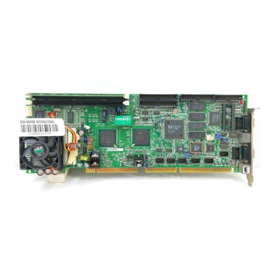
Page 7: Chapter 2. Installation
Chapter 2. Installation This chapter describes how to install the ROCKY-538TXV. First, the layout of ROCKY-538TXV is shown, then the unpacking information that you should be careful is described. Reference information on how to set the jumpers and switches for ROCKY-538TXV's configuration, such as CPU type selection, system clock setting, and watch dog timer, are also included. -
Page 8: Unpacking
Do this only with the board place on a firm flat surface. Note : DO NOT APPLY POWER TO THE BOARD IF IT HAS BEEN DAMAGED. You are now ready to install your ROCKY-538TXV Single Board Computer. -
Page 9: Cpu Settings For Rocky-538Txv
2.3 CPU Settings for ROCKY-538TXV... - Page 10 CPU Clock Setting : Speed/Clock 11-12 13-14 55MHz OPEN SHORT SHORT OPEN 60MHz OPEN SHORT OPEN OPEN 66MHz OPEN OPEN OPEN OPEN CPU to Bus Multiple : Multiplier 9-10 1.5 x OPEN OPEN OPEN SHORT OPEN OPEN 2.5x SHORT SHORT OPEN OPEN SHORT...
- Page 11 Dual / Single CPU Voltage setting: Vcore & VIO JP10 JP11 Pentium® SHORT SHORT OPEN OPEN (P54C) Pentium® AMD K6 OPEN OPEN SHORT SHORT Cyrix 6x86MX Dual Voltage Intel Low- Power OPEN OPEN OPEN OPEN Embedded Processor Cyrix 6x86MX PR Rating Table ( Vcore : 2.9V,dual voltage ) CPU Core Clock...
-
Page 12: Ps/2 Mouse Irq12 Setting
2.4 PS/2 Mouse IRQ12 Setting The on board PS/2 mouse will use IRQ12 in operation.. JP16 : IRQ12 Enable/Disable Setting JP16 DESCRIPTION SHORT IRQ12 Enable for PS/2 Mouse Operating OPEN PS/2 Mouse Disable. IRQ12 to bus 2.5 Watch-Dog Timer The Watch-Dog Timer is enabled by reading port 443H. It should be triggered before the time-out period ends, otherwise it will assume that program operation is abnormal and will issue a reset signal to start again, or activate NMI to CPU. -
Page 13: Battery Backup For Cmos Setup
JP1 : Clear CMOS Setup (Reserve Function) DESCRIPTION Normal Operation Clear CMOS Setup 2.8 Battery Backup for CMOS Setup There is one 4-pin header CN8 used for battery backup function. When set to short, pin 1-2 will be using on board battery. When using external battery, you should take off the jumper and use the connector as an external battery connector. -
Page 14: Chapter 3. Connection
Chapter 3. Connection This chapter describes how to connect peripherals, switches and indicators to the ROCKY-538TXV board. 3.1 Floppy Disk Drive Connector ROCKY-538TXV board is equipped with a 34-pin daisy-chain driver connector cable. CN2 : FDC CONNECTOR DESCRIPTION DESCRIPTION GROUND... -
Page 15: Pci E-Ide Disk Drive Connector
3.2 PCI E-IDE Disk Drive Connector You can attach four IDE (Integrated Device Electronics) hard disk drives to the ROCKY-538TXV IDE controller. The IDE support Ultra DMA/33 interface. CN1(IDE 1) : Primary IDE Connector CN4(IDE 2) : Secondary IDE Connector... -
Page 16: Parallel Port
Parallel Port This port is usually connected to a printer. The ROCKY-538TXV includes an on- board parallel port accessed through a 26-pin flat-cable connector CN3. CN3 : Parallel Port Connector DESCRIPTION DESCRIPTION STROBE# DATA 0 DATA 1 DATA 2 DATA 3... -
Page 17: Keyboard Connector
3.5 Keyboard Connector The ROCKY-538TXV provides two keyboard connectors. CN6 : 5-pin Header Keyboard Connector DESCRIPTION KEYBOARD CLOCK KEYBOARD DATA GROUND CN16 : 6-pin Mini-DIN Keyboard Connector DESCRIPTION KEYBOARD DATA GROUND KEYBOARD CLOCK 3.6 External Switches and Indicators There are many external switches and indicators for monitoring and controlling your CPU board. -
Page 18: External Battery Connector
CN8 ’s pin on 1-2 jumper. Then connect the external battery to pin 1-4. CN8 : External Battery Connector DESCRIPTION External Battery + Ground 3.9 USB Port Connector The ROCKY-538TXV has two built-in USB ports for the future I/O bus expansion. CN14 : USB 0 CN15 : USB 1 DESCRIPTION DATA- DATA+ GROUND 3.10 IrDA Infrared Interface Port... -
Page 19: Vga Connector
GROUND 3.12 Fan Connector The ROCKY-538TXV provides a CPU cooling fan connector and a chassis fan connector. These connectors can supply 12V/500mA to the cooling fan. There is a “rotation” pin in this connector. The rotation pin is used to retrieve fan’s rotation signal back to the system enabling system BIOS to recognize fan speed. -
Page 20: Standby Connector For Atx Power Supply
3.13 5V Standby Connector for ATX power supply • ATX Power Supply 20-pin power connector 5V standby PW-0K Ground Ground Ground Ground Ground Suspend Control Ground Ground 3.3V -12V 3.3V 3.3V... -
Page 21: Chapter 4. Award Bios Setup
Chapter 4. AWARD BIOS Setup The ROCKY-538TXV uses the AWARD PCI/ISA BIOS for system configuration. The AWARD BIOS setup program is designed to provide maximum flexibility in configuring the system by offering various options which may be selected to meet end-user demands. -
Page 22: Standard Cmos Setup
4.2 Standard CMOS Setup The Standard CMOS Setup is used for basic hardware system configuration. Main function is to modify Date/Time settings and Floppy/Hard Disk Drive settings. Please refer the following screen for this setup. For IDE hard disk drive setup, please check the following possible setup procedure: Use Auto setting for detection during bootup. -
Page 23: Bios Features Setup
4.3 BIOS Features Setup BIOS Features Setup is designed for customer’s to tune ROCKY-538TXV board to its best performance possible. As for normal operations, customers don’t have to change any default setting as the default setting is pre-set for most reliable operation. -
Page 24: Chipset Features Setup
4.4 Chipset Features Setup Most of these setup functions are working for ChipSet (Intel 430TX). These options are used to change the ChipSet‘s registers. Please be careful while making changes to any default setting, otherwise the system could become unstable. Auto Configuration : Enable or Disable When you are using 60nS general type DRAM, please enable this setting so as to get optimal timings. -
Page 25: Integrated Peripherals
4.5 Integrated Peripherals This part of setup for Multi-I/O Chip (W83977F ). These options are used to change the ChipSet‘s registers. Please be careful while making any changes to default setting so as to meet your application needs. The only special point that you must pay attention to in this menu page is the Onboard Serial Port2. -
Page 26: Power Management Setup
4.6 Power Management Setup Power Management Setup help users in modifying ROCKY-538TXV board‘s “green” function. These features could shut down video display and hard disk in order to save energy. Please refer to the sample caption below for power management setup screen:... -
Page 27: Pnp/Pci Configuration
4.7 PNP/PCI Configuration The PNP/PCI Configuration help users to set ROCKY-538TXV board’s “PCI” function. All PCI bus slots on the system use INTA#, thus all installed PCI slots must be set to this value. PNP OS Installed : Yes or No When PNP OS is installed, interrupts may be reassigned by the OS when the setting is Yes. -
Page 28: Appendix A. E 2 Key™ Function
A quick and easy way to learn to use the function is to first review EKEYDEMO.C code included. Please note the E KEY™ function is only available if the parallel port is working. In other words, you should enable ROCKY-538TXV’s parallel port, otherwise will this function will be not working. -
Page 29: Appendix B. Watch-Dog Timer
Appendix B. Watch-Dog Timer The Watch-Dog Timer is provided to ensure that standalone systems can always recover from catastrophic conditions that caused the CPU to crash. This condition may have occurred by external EMI or a software bug. When the CPU stops working correctly, hardware on the board will either perform a hardware reset (cold boot) or a non-maskable interrupt (NMI) to bring the system back to a known state.
Need help?
Do you have a question about the ROCKY-538TXV and is the answer not in the manual?
Questions and answers