Table of Contents
Advertisement
Quick Links
Advertisement
Table of Contents

Related Manuals for KERN OCO-2


Summary of Contents for KERN OCO-2
- Page 1 KERN OCO-2 Operating Manual Inverted System Microscopes...
-
Page 2: Table Of Contents
Content 1. Introduction ..........................1 2. Safety Symbols ..........................1 3. Meaning of the text symbols......................2 4. Precautions When Unpacking the Microscope ................2 5. Module Nomenclature See diagram 1 ..................3 6. Preparation for use........................4 7. Preparations for the use of special devices...................6 8. -
Page 3: Introduction
1. Introduction Dear friend, thank you for using the inverted biological microscope made by our company. It is our great honor to have you as our subscriber. In order to give you timely knowledge of how to use the product, we have especially written this manual. Efforts have been made to ensure thoroughness in contents, and brevity in style. -
Page 4: Meaning Of The Text Symbols
3. Meaning of the text symbols. Caution: Negligence of the warnings in the manual may cause Physical harm or mechanic damage (the objects nearby may also be affected). ! Caution: Negligence of the warnings in the manual may cause Physical harm or mechanic damage (the objects nearby may also be affected). -
Page 5: Module Nomenclature See Diagram 1
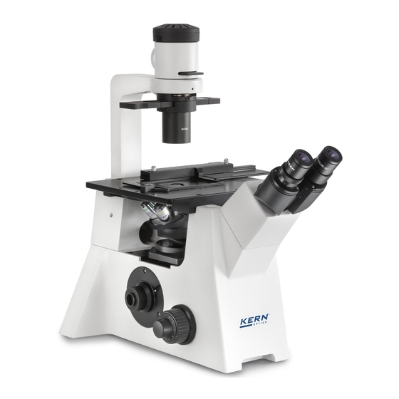
5. Module Nomenclature See diagram 1... -
Page 6: Preparation For Use
6. Preparation for use Please refer to diagram 1 on page 3 about the names of the following items. Attaching the Eyepieces 6-1-1 Remove the eyepieces' dust caps. 6-1-2 Insert G10X eyepiece into the eyepiece sleeve. Attaching the Objectives 6-2-1 Remove the stage center plate and attach the objectives to the revolving nosepiece through the hole on the stage left by the plate. - Page 7 Attaching the Holder for 76mm * 76mm slice 6-5-1 This part is used for the observation of the76mm * 76mm slice. 6-5-2 Open the spring clip of the rectangular stage with flexible right handle, slide the holder into its right position (Be sure that the rectangular groove facing up), loose the clip gently, and finally put the Slice in place.
-
Page 8: Preparations For The Use Of Special Devices
6-8-2 While holding the mounting lever of the filter holder, insert a filter. (1) Hold the filter by its edge to avoid leaving fingerprints or smudges on the filter surfaces. (2) After the illumination has been ignited, the filter will be very hot. Be sure to set the main switch to "O"(OFF) and allow the filter holder and filters to cool down before replacing filters. -
Page 9: Operations
7-3-2 For detailed information, please refer to the specifications about patch clamp, thermostatic cover, and the thermostatic stage. 8. Operations 8-1 The procedure of transmitted light bright field observation and phase contrast observation, please refer to diagram 2 in page 08. For more detail information, please refer to 8-2 and 8-3. Transmitted light brightfield observation Set the main switch to "I"(ON) and adjust the intensity of illumination. - Page 10 8-2 The details of transmitted light brightfield observation procedure 8-2-1 Set the main switch to "I"(ON) and adjust the intensity of illumination. A. Make sure that the light intensity control knob is in the MIN(minimum intensity)position and set the main switch to "I"(ON).
- Page 11 (3) Detaching the Fine Adjustment Knob The fine adjustment knob is designed detachable in order to prevent interference between the knob and the operator's hand manipulating the X- and Y- axis knobs. Loosen the clamping screw using the Allen screwdriver and remove the fine adjustment knob.
- Page 12 8-2-12 Insert the filters(Please refer to 6.8) 8-2-13 Adjust the brightness 8-2-14 Start observation Observation of phase contrast 8-3-1 Set the main switch to "I"(ON)(Please refer to 8.2.1) 8-3-2 Disengage the filter other than frost filter from the light path. 8-3-3 Select the light path with the light path selector lever.
- Page 13 8-3-10 Place the specimen on the stage. 8-3-11 Bring the specimen into focus. 8-3-12 Adjust the brightness. 8-3-13 Adjust the interpupillary distance and diopter. 8-3-14 Engage the objective to be used in the light path and bring the specimen in focus.
-
Page 14: Troubleshooting Guide
9. Troubleshooting Guide Under certain conditions, performance of the microscope may be adversely affected by factors other than defects. If problems occur, please review the following list and take remedial action as needed. If you cannot solve the problem after checking the entire list, please contact your local representative for assistance. - Page 15 Problem Cause Remedy f ) Visibility of the image is Poor contrast during Replace the plastic culture poor: observation. vessel with a glass vessel. Image is not sharp. Contrast is poor. Details are poorly visible. g) The image is blurred. Objective engaged Make sure that revolving...
-
Page 16: Maintenance Of The Microscope
power cord from the wall outlet, then allow the old bulb and lamp socket to cool before replacing the bulb with a new of the designated type. 2 Attaching the Lamp Socket Insert the plug into the socket, then push the guide pins gently into the guide holes. 10.
Need help?
Do you have a question about the OCO-2 and is the answer not in the manual?
Questions and answers