Table of Contents
Advertisement
Quick Links
Advertisement
Table of Contents

Related Manuals for KERN OPTICS OKO-1


Summary of Contents for KERN OPTICS OKO-1
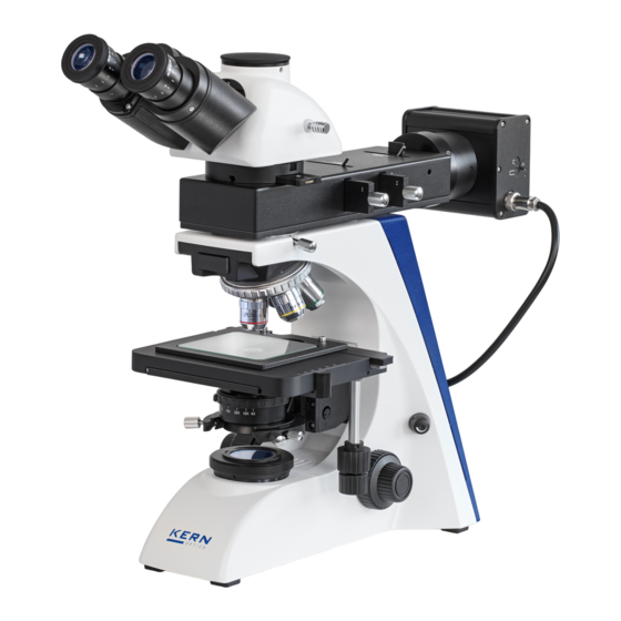
- Page 1 KERN & Sohn GmbH Ziegelei 1 Tel: +49-[0]7433- 9933-0 D-72336 Balingen Fax: +49-[0]7433-9933-149 Email: info@kern-sohn.com Internet: www.kern-sohn.com Operating instructions Metallurgical microscope KERN OKO-1 OKO 178 Version 1.1 01/2021 OKO-1-BA-en-2111...
-
Page 3: Table Of Contents
KERN OKO-1 Version 1.1 01/2021 Operating instructions Metallurgical microscope Table of Contents Before use ..................3 General information ......................... 3 Notes on the electrical system ....................3 Storage ............................4 Maintenance and cleaning ....................... 5 Nomenclature ................6 Technical data / equipment ............9 Assembly .................. -
Page 4: Before Use
1 Before use 1.1 General information The packaging must be opened carefully to prevent the accessories inside from falling to the floor and breaking. In general, a microscope should always be handled with great care, as it is a sensitive precision instrument. -
Page 5: Storage
1.3 Storage Avoid exposing the device to direct sunlight, high or low temperatures, shock, dust and high humidity. The suitable temperature range is 0 - 40° C and a relative humidity of 85 % should not be exceeded. The device should always be placed on a firm, smooth and horizontal surface. When the microscope is not in use, it is best to cover it with the dust cover provided. -
Page 6: Maintenance And Cleaning
• Special cleaner for optical lenses • Special optical cleaning cloths • Bellows • Brush With proper handling and regular inspection, the microscope will operate smoothly for many years. However, if a repair is necessary, contact your KERN dealer or our Technical Service. OKO-1-BA-en-2111... -
Page 7: Nomenclature
2 Nomenclature Camera adapter Eyepieces connector Microscope head / tube Locking screw/ Microscope head Objective nosepiece LED incident light unit Lens Object holder Dial X - Y axis Object table Object table Condenser with aperture adjustment Dimmer Centering screw Coarse and Condenser fine drive Field lens with... - Page 8 Rear view LED incident light unit Carrying handle Coarse and fine drive Power cable for incident Main switch Mains Fuse connection OKO-1-BA-en-2111...
- Page 9 Incident light unit Insertion for diffuser Aperture diaphragm Lamp housing Luminous field diaphragm Colour filter Polariser Analyser OKO-1-BA-en-2111...
-
Page 10: Technical Data / Equipment
3 Technical data / equipment Dimensions Product: 550x200x460 mm Dimensions Packing: 520x470x430 mm Net weight: 12 kg Gross weight: 16 kg Input voltage: AC 100-240V, 50-60Hz Output voltage: DC 1.2-6V Fuse: 2A 5x20mm OKO-1-BA-en-2111... - Page 11 OKO-1-BA-en-2111...
-
Page 12: Assembly
4 Assembly OKO-1-BA-en-2111... -
Page 13: Incident Light Unit
4.1 Incident light unit First, the lamp housing and the incident light unit must be brought together at their connection points. Then the connection is fixed via an Allen screw on the right at the connection point of the lamp housing. Analyzer, polarizer and color filter slides can now be placed in the appropriate slots (see page 8). -
Page 14: Eyepieces
4.4 Eyepieces Always use eyepieces with the same magnification for both eyes. These are simply placed on the tube sockets after first removing the protective plastic caps. There is no fixation possibility. You should always make sure that the lenses are not touched with your bare fingers and that no dust enters the openings. -
Page 15: Operation
5 Operation 5.1 First steps The first thing to do is to connect the power supply by means of a mains plug. The light intensity control (dimmer) should first be set to a low level, so that the eyes are not immediately exposed to too much light when looking into the eyepieces for the first time. -
Page 16: Pre-) Focusing
5.2 (Pre-) Focusing In order for an object to be observed, it must be at the correct distance from the lens so that a sharp image can be obtained. To find this distance initially (without any other presettings of the microscope), bring the objective with the lowest magnification into the beam path, look with the right eye through the right eyepiece and turn the coarse adjustment knob slowly at first (see illustration). -
Page 17: Adjusting The Eye Relief
5.3 Adjusting the eye relief In binocular viewing, the interpupillary distance must be precisely adjusted for each user to obtain a clear image of the object. While looking through the eyepieces, hold the left and right tube housings with one hand each. By pulling them apart or pushing them together, the interpupillary distance can be either increased or decreased (see illustration). -
Page 18: Setting The Magnification
5.5 Setting the magnification After pre-focusing using the objective with the lowest magnification (see section 5.2), the total magnification can now be adjusted as required using the revolving nosepiece. By rotating the revolver, any of the four other objectives can be brought into the beam path. -
Page 19: Using The Eyecups
5.6 Using the eyecups The eyecups included in the scope of delivery can basically always be used, as they shield disturbing light that is reflected from light sources in the surroundings at the eyepiece, thus resulting in better image quality. But mainly, if eyepieces with a high viewpoint (especially suitable for eyeglass wearers) are used, then it can be useful for users without glasses to attach the eyecups to the eyepieces. -
Page 20: Adjustment Of Köhler Illumination For Transmitted Light
5.7 Adjustment of Köhler illumination for transmitted light In order to obtain perfect image results during microscopic observation, it is important that the light guidance of the microscope is optimized. If illumination can be adjusted according to Köhler, this results in homogeneous illumination of the specimen and the reduction of disturbing stray light. - Page 21 3. Adjust the height of the condenser until the image of the field diaphragm appears sharp in the field of view. With some microscopes, there is a danger of raising the condenser too high and causing a collision with the specimen slide. A little caution is therefore required here.
- Page 22 6. Use the aperture diaphragm of the condenser to set the optimum compromise between contrast and resolution for the microscopic image. The scale graduation on the condenser is a guide value. Select according to the detented objective. The view into the tube, without the eyepiece should look something like the picture on the right.
-
Page 23: Adjustment Of The Illumination For Incident Light
5.8 Adjustment of the illumination for incident light Just like the components of transmitted light illumination, those of reflected light illumination can be adapted to different application requirements. The following components are available: Luminous field diaphragm and aperture diaphragm The two shutters have the same functions as explained in the transmitted light setting (see section 5.7). -
Page 24: Lamp Replacement
6 Lamp replacement The devices of the OKO-1 series are equipped with LEDs. Due to the long service life of LED illumination, regular lamp replacement will not be necessary with these microscopes. Problems with the lighting would therefore in most cases have defects in the electrical system as the cause. -
Page 25: Use Of Optional Accessories
8 Use of optional accessories 8.1 Polarization unit (transmitted light) The polarization unit consists of a polarizer and an analyzer. The same slide that is part of the incident light unit is used as the analyzer (see figure on page 8). The polarizer is a round element with a black frame and a dark glass pane in the middle. -
Page 26: Camera Connection
8.2 Camera connection In case of using a trinocular tube, it is possible to connect microscope cameras to the instrument in order to digitally document images or sequences of an observation object. After removing the plastic cover from the camera adapter port on top of the microscope head, a suitable adapter must first be attached to it. -
Page 27: Troubleshooting
9 Troubleshooting Problem Possible causes Mains plug not inserted correctly No power available at the socket Lamp does not burn Lamp defective Fuse defective Aperture diaphragm and/or field diaphragm are not open wide enough The beam path selection slider is set to Field of view is dark "Camera". - Page 28 Problem Possible causes Aperture diaphragm is not open wide enough Condenser is lowered too far The objective does not belong to this microscope Blurred details The front lens of the lens is dirty An immersion lens is used without immersion Bad picture Poor contrast The immersion oil contains air bubbles...
-
Page 29: Service
The device may only be opened by trained service technicians authorised by KERN. 11 Disposal The packaging is made of environmentally friendly materials that you can dispose of at local recycling points.
Need help?
Do you have a question about the OPTICS OKO-1 and is the answer not in the manual?
Questions and answers