Table of Contents
Advertisement
Quick Links
Advertisement
Table of Contents

Related Manuals for Parker IM20 Series


Summary of Contents for Parker IM20 Series
- Page 2 Parker or its subsidiaries or authorized distributors. To the extent that Parker or its subsidiaries or authorized...
-
Page 3: Table Of Contents
Interface Summary............................6 1.1 Product Check ..........................6 1.2 Servo Drive Nameplate ........................ 6 1.3 Servo Motor Nameplate ....................... 6 1.4 Servo drive naming rule ....................... 7 1.5 Servo motor naming rule ......................8 1.6 Appearance ..........................10 1.7 Precautions ..........................10 1.7.1 Installation instructions ....................... - Page 4 System wiring ......................... 22 4.1 System construction ........................22 4.2 Connection ..........................23 4.2.1 Main circuit connection ...................... 24 4.2.2 Functions of control terminals .................... 24 4.2.3 Analog channel switchover ....................26 Keypad panel ..........................27 5.1 Panel Illustration ........................27 5.2 Panel Operation ..........................
- Page 5 8.3 Storage ............................53 Appendix 1 Zoom Table of Function Code ..................54 Appendix 2 Expand card ........................65 Appendix 3 Servo motor structure diagram ..................66 Appendix 4 Communication (V1.0) ....................70...
-
Page 6: Summary
0 ~INPUT 0 ~590.0 3 PH OUTPUT Parker Hannifin Motion and Control ( Wuxi ) Company Ltd , No. 200 , Furong Zhong Si Lu , Xishan Economic Development Zone , Wuxi , 214192, Jiangsu, China IP20 Made in china BS NO. -
Page 7: Servo Drive Naming Rule
Parker Hannifin Corporation www.parker.com TYPE:FM17-0110R6EEDFL =64N.m I =23A Ke=290.7V/1700r/min =1700/2000r/min IMB5 IP54 TH.CI.F FM170110R6EEDFL201701002 Fig 1-3 Servo Motor Nameplate 1.4 Servo drive naming rule IM20 0110 T3 E5 141 × 150 × 237 156 × 170 × 265 205 × 196 × 340 265 ×... -
Page 8: Servo Motor Naming Rule
D2 B1 Remark Cooling mode Forced air-cooling Remark Filter C3 Level filter Default No filter Remark Brake B1/ Default Built-in brake Encoder Remark D2/ Default Differential resolver Remark Communication Modbus connected by F2/ Default terminal interface Fig 1.4.2 Optional function naming rule 1.5 Servo motor naming rule Shaft Keyway shaft with C hole... - Page 9 FM 17 0110 S, L, … Design code Air- cooling Cooling mode Without cooling fan Keyway shaft Shaft Internal spline shaft Brake Without brake 200 Flange Flange size 266 Flange Bus voltage 600 V Feedback Resolver 0075 7.5 kW 0110 11 kW Rated power 0180...
-
Page 10: Appearance
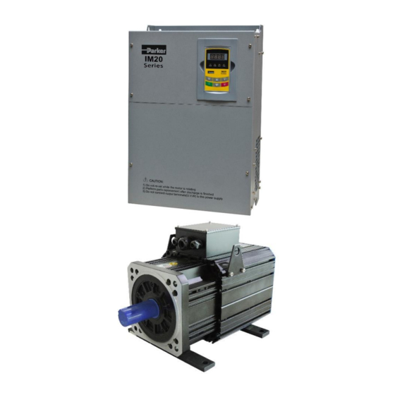
1.6 Appearance IM20 series servo drive adopts metal hanging housing. Its appearance and structure are shown as in figure in the right, with detachable one-side door hinge structure adopted for front cover, convenient for wiring and maintenance. 1.7 Precautions 1.7.1 Installation instructions ●... -
Page 11: Servo System Specifications And Model Selection
II. Servo system Specifications and model selection 2.1 Servo Drive Specifications and parameters 2.1.1 Specifications Item Instructions Rated voltage Three-phase 380V -15%~10% Input Rated frequency 50/60Hz ±5% Rated voltage Three-phase 0~INPUT Output Frequency range 0.00~590.00Hz Structure Hanging. Protection grade: IP20 Cooling mode Forced air cooling Speed feedback... -
Page 12: Wiring And Ferrite Core Recommended
F2D2B1R3CP3 IM20-S0075T3E4 75Ω260W 25.5 2.96 FT330-40A F2D2B1R3CP3 IM20-S0110T3E5 50Ω500W 34.5 3.61 FT330-50A F2D2B1R3CP3 IM20-S0150T3E5 30Ω500W 3.65 FT330-50A F2D2B1R3CP3 IM20-S0185T3E6 30Ω1kW 7.32 FT330-60A F2D2B1R3CP3 IM20-S0220T3E6 15Ω1.5kW 7.56 FT330-80A F2D2B1R3CP3 IM20-S0300T3E7 15Ω1.5kW 12.6 FT330-100A F2D2B1R3CP3 IM20-S0370T3E7 15Ω4kW 112.5 12.8 FT330-120A F2D2B1R3CP3 IM20-S0450T3C4 15Ω4kW 24.5 FT330-150A... -
Page 13: Servo Motor Specifications
* represents cable length (unit is m), 3m, 4m, 6m length is optional. Resolver cable must be made from shielded twisted pair to ensure electromagnetic compatibility and reliability. Please select Resolver cable as short as possible. Parker standard length is 3m. Resolver cable is not standard configuration. - Page 14 FMMB-302R6AED None 1500 FMMB-432R6AED None 1500 FMMB-552R6AED None 12.5 1500 FMMA-222R67ED None 2000 FMMA-312R67ED None 2000 37.5 FMMA-352R6AED 17.2 None 2000 FMMA-452R6AED 21.5 None 2000 FMMA-602R6AED None 2000 FMSA-182R65ED None 3000 FMSA-232R67ED None 3000 FMSA-302R67ED None 3000 FM15-0082R6EEDFL 16.6 1500 FM15-0100R6EEDFL 20.7 1500...
-
Page 15: Recommended Configuration
1059 2.3 Recommended configuration Parker pump is highly recommended for stable and reliable, high efficiency, energy saving, and low noise. User can refer to pump manual for instruction. Please pay attention to max rotating speed of oil pump to avoid damage. -
Page 16: Combined-Configuration
4. Braking resistor Please select braking resistor referring to motor interia, system inertia, deceleration time, etc. For multi-pump confluent system with high performance, please select resistor of high rated power for master drive. Note: if motor band is different, cooling mode is different, denominator coefficients of rated torque and power is different. - Page 17 IM20-S0370T3E7 F2D2B1R3CP3 FM17-0330R6F 2100 IM20-S0450T3C4 F2D2B1R3CP3 FM17-0400R6F 2100 IM20-S0550T3C5 F2D2B1CP3 FM17-0450R6F 2100 IM20-S0750T3C5 F2D2B1CP3 FM17-0550R6F Note:Parker can provide total solution together combine with Parker Hydraulics product, we also delivered lots of successful applications. For more details, please contact Parker sales.
-
Page 18: Installation
III. Installation 3.1 Servo drive installation 3.1.1 Servo drive structure Fig 3-1 Installation Sketch Rated Structure code External size(A×B×H) Installation size (W×L) Screw power 141×150×237(mm) 126×225 (mm) 4\5.5\7.5KW 156×170×265(mm) 146×255 (mm) 11\15KW 205×196×340(mm) 194×330 (mm) 18.5\22KW 265×235×435(mm) 235×412 (mm) 30\37KW 315×234×480(mm)... -
Page 19: Servo Motor Installation
Fig 3-2 Installation Sketch 3.2 Servo motor installation Please do not strike motor shaft ends, to avoid ruining bearing or speed sensor. Note: please install motor in a ventilated place, to avoid motor demagnetization because motor temperature is too high. Motor pump Fig 3-4 Correct installation mode... -
Page 20: Braking Unit And Braking Resistor
3.3 Braking unit and braking resistor Optional braking unit: HFBU-DR series. Braking resistor must be non-inductive resistor. Same power resistors have same dimension. Braking voltage of braking unit can be adjusted by switching code SW1. Switching Switching Switching Braking Power code 1 code 2 code 3... - Page 21 External size Installation size Resistor Resistor type Hole size power Length (W) Length (A) Width (B) Height (H) (Ф) Ф6.5±0.3 500W 360±3.0 50±1.0 91±3.0 338±3.0 non-inductive resistor Ф6.5±0.3 350±3.0 60±2.0 119±3.0 325±5.0 non-inductive resistor Ф6.5±0.3 1.5kW 484±5.0 68±1.0 125±3.0 454±4.0 non-inductive resistor Ф6.5±0.3 557±5.0...
-
Page 22: System Wiring
IV. System wiring 4.1 System construction Hydraulic Pressure cylinder Flow Control signal Up level control Fault Control valve signal Encoder Pressure feedback signal Pressure sensor Braking UVW Motor cable RST power cable resistor/ Braking unit Servo motor Oil pump AC220V Fig 4-1 System construction Note: during working of the oil pump, the pipe may go empty and hence into a vacuumized state. -
Page 23: Connection
CAN + Encoder signal and cable colour is ▼ CAN - corresponding to TAMAGAWA resolver TS2640N321E64 Relay output Pressure setpoint Parker IM 20 Feedback pressure AI 2 Servo Drive Flow setpoint AI 3 Analog grounding Wind signal cables 2 Open-collector... -
Page 24: Main Circuit Connection
4.2.1 Main circuit connection Output Input ~ 380V Grounding Braking resistor Fig 4-3 Main circuit connection (The figure is only sketch, terminals order of practical products may be different from the above-mentioned figure.) Fig 4-1 Introduction of terminals of power loop Terminal Terminal marking Terminal Function Description... - Page 25 normally open contacts. The contact capacity is 6A/125VAC, 3A/250VAC and 3A/30VDC. AO1-GND It is connected with frequency meter or speedometer externally, and its Analog token output negative is connected with GND. The output range is 0~10V. AO2-GND AI1-GND Voltage analog input Pressure given input terminal. The grounding terminal is GND. AI2-GND Input signal Voltage analog input Pressure feedback input terminal.
-
Page 26: Analog Channel Switchover
1 Switch J3: Turn J3 to PNP, 24V is common terminal. Turn J3 to NPN, CM is common terminal. 2 Switch J4: Turn J4 to left, AI1 voltage signal can only be +10V signal, turn J4 to right, AI1 voltage signal ±... -
Page 27: Keypad Panel
V. Keypad panel 5.1 Panel Illustration The panel covers three sections: data display section, status indicating section and keypad operating section, as shown in Fig. 5-1. LED shows running frequency, flashing target frequency, function code, parameter value or fault code. 4 LEDs indicate working status. - Page 28 increasing or decreasing by degrees within F100~F160; press “O” key again, DGT indicator will be off. When pressing “▲”/ “▼” key, function codes will toggle among the 10 code-groups, like F211, F311… F111…, Refer to Fig 5-2 Enter correct user’s Display Display password (currently...
-
Page 29: Panel Display
5.5 Panel Display Items and Remarks Displayed on the Panel Items Remarks -HF- It indicates servo drive is resetting. Fault code, indicating “over-current ”, “over-voltage”, “servo drive over-load”, “motor over-load”, “servo drive over-heat”, "motor over-heat", “Emergency OC, OE, OL1, OL2, stop”, “under-voltage protection”, “out-phase for input”, “pressure sensor OH, ESP, ESP1, LU, “Pump... -
Page 30: Function Parameters
5.6 Function Parameters 5.6.1 Basic parameters F100 User’s Password Mfr’s value: 8 Setting range: 0~9999 ·When F107=1 with valid password, the user must enter correct user’s password after power on or fault reset if you intend to change parameters. Otherwise, parameter setting will not be possible, and a prompt “Err1” will be displayed. - Page 31 stop. 1: External analog AI1; 2: External analog AI2 6:External analog AI3 The frequency is set by analog input terminal AI1, AI2 and AI3. 10. MODBUS communication for multiple pump control When auxiliary pump is adopted, speed command is given by master pump through MODBUS. 11.485 communication for multiple pump control When auxiliary pump is adopted, speed command is given by master pump through 485 communication.
-
Page 32: Multifunctional Input And Output
F209 Selecting the mode Setting range: Mfr’s value: 0 of stopping the motor 0: stop by deceleration time; 1: free stop When the stop signal is input, stopping mode is set by this function code: F209=0: stop by deceleration time Servo drive will decrease output frequency according to setting acceleration/deceleration curve and decelerating time, after frequency decreases to 0, servo drive will stop. - Page 33 Note: when user selects Parker double-pump, related parameters should be set. Please refer to 5.6.8. Instructions for digital multifunctional output terminal (F300-F302): Value Function Instructions No function Output terminal has no functions. Fault protection DO goes high on Fault. Servo on...
-
Page 34: Analog Input And Output
Pressure presetting When this terminal is valid, main pump controller will work according terminal of master to the pressure set by FB10 not given by analog. pump 5.6.4 Analog input and output Function Definition Setting range Mfr's value Note code △... -
Page 35: Braking And Protection
Correspondence of output voltage range (0-5V or 0-10V) to output frequency is set by F424 and F425. For example, when F423=0, F424=10 and F425=120, analog channel AO outputs 0-5V and the output frequency is 10-120Hz. AO output compensation is set by F426. Analog excursion can be compensated by setting F426. Token contents output by analog channel are selected by F431. - Page 36 Alarm time of Resolver √ FB48 0~3.0 magnetic-field angle wrong Alarm time of motor with √ FB49 0~5.0 locked rotor Rotating Resolver fault √ FB57 0: Invalid 1: Valid testing enable √ FB58 Reverse running limit enable 0: Invalid 1: Valid Time of pressure sensor test 0~100.0 (Invalid √...
-
Page 37: Motor Parameters
pressure sensor fault will occur and servo drive stops and trip into PP-1. FB60 is used to set pressure feedback threshold, if pressure feedback value is always lower than setting value, pressure feedback sensor fault will occur. FB61 is the current threshold, if the current is higher than this value, servo drive will start to check whether pressure feedback sensor has fault. - Page 38 Phase resistor of stator F910 0~9.999 Subject to model × coil √ Current loop KP1 FA25 0~300 Subject to model √ Current loop KI1 FA26 0~300 Subject to model √ FA27 Current loop KP2 0~300 Subject to model √ FA28 Current loop KI2 0~300 Subject to model...
-
Page 39: Pressure Control Parameters
5.6.7 Pressure control parameters Function Definition Instructions code The higher the value is, the faster the response is, and pressure rises Pressure ascent faster. If the value is too high, pressure will be not steady. The lower the F735 segment proportional value is, the slower the response is, and pressure rises slower. - Page 40 Pressure descent Please increase this value if pressure overshoots during rising. Please F746 segment differential decrease this value when pressure rises slowly. Kd 2 Pressure stable When feedback pressure is in stable region, F741-F746 is used for PID F760 region% control.(Software version must be above 1.32) If the value is too high, the response is slow, pressure will rise in an arc.
- Page 41 during ascent segment During pressure-holding Step 1: decrease F739 and increase F740 process, pressure overshoot Step 2: increase F738. from high-voltage to Step 3: step 1+step 2 low-voltage Step 1: decrease F735 and increase F738 Step 2: decrease F737 and F740. Injection unit vibration Step 3: step 1+step 2 Second voltage rising...
-
Page 42: Multiple Pump Combined Control
FB52 System minimum pressure setting Setting range: 0~50bar Mfr’s value: 5 FA29 is used to set motor min speed when molding machine does not give any command. Proper minimum speed will increase pressure response speed, but oil pump will act even when molding machine does not give any command. - Page 43 FC37 0.000~0.100 0.000 FC25~FC37 are used for Parker double pump function. FC 25 is used to select double pump function. When FC25=0, double pump control is invalid. When FC25=1, double pump control is valid. FC26 and FC27 are set for switching big pump.
- Page 44 F203 F905 FA30 FC00 FC01 FC02 Master Master pump Master pump pump capacity capacity capacity FC03 ~ Auxiliary Auxiliary Auxiliary FC08 pump pump pump capacity capacity capacity Note: Indicating default value that can not to be modified. One of CAN communication, 485 communication and analog control can be selected for combined control.
- Page 45 Power supply Pressure Pressure Flow of PG card given feedback given Analog Inject EnableResetStop ground PRV SYS SPV COS+ COS - RE1 RE2 SIN+ SIN- 24V CM DI1 DI2 AI1 AI2 +15V -15V DO2 DO3 DO4 CAN + /- Connect to other Relay output Motor KTY84 Analog output,...
-
Page 46: Injection Molding Machine Debugging
Resolver cable must be connected to servodrive control PCB correctly. 6.2 Servo motor parameter (1) Before servo drive runs, user must input motor nameplate parameters. IM20 series drive matches with standard motor parameters based on nameplate. Accurate paramters can bring excellent performance. -
Page 47: Max Pressure Setting
Flow command: 0~ Max flow is corresponding to 0~10V, set value to FA22 and FA 21. Set FA18 by pressure sensor specification. Feedback base pressure of pressure sensor detection: under no pressure and no flow state, test AI2/GND voltage and set it to FA19. (2) Fb16, Fb17, Fb18 is corresonding to AI1, AI2, AI3 monitor value separately. -
Page 48: Trouble Shooting
VII. Trouble Shooting When servo drive malfunctions, don’t run by resetting immediately. Check any causes and get it removed if there is any. Take counter measures by referring to this manual in case of any malfunctions on servo drive. Should it still be unsolved, contact the manufacturer. - Page 49 Current zero *Flat cable is loosened. *check the flat cable. excursion ERR4 *Current detector is broken. *ask for help from manufacture. malfunction *Pressure sensor damaged; *replace pressure sensor; *Pressure sensor oil outlet blocks up; *check and dredge oil outlet; Pressure sensor * Pressure sensor power malfunction;...
- Page 50 Er75 Copy forbidden Copy is forbidden while F638=0. *Set F638=1 or 2. Common trouble shooting System gives pressure and flow command, but motor doesn’t rotate. (1) Servo drive doesn’t run. Servo drive does not receive pressure and flow command. Check whether DI3 terminal is connected correctly, whether signal source is correct. Make sure F200=F201=2, RUN indicator light is normally on.
- Page 51 ≥1.4 Max pressure of pressure sensor /system Max pressure Oil pump is damaged and oil is not sufficient. Check servodrive standby current, which should be lower than 3A. If current is too high, check motor and Resolver wiring, check commutation again. System pressure is not stable or can not reach Max pressure.
- Page 52 (3) Setting melt glue position is bigger than system max value. (4) Injection valve fault. Please change and clean cushion rubber. Motor speed is not enough or not stable in injection and glue melt process. (1) Increase FB79 and FB80. (2) Adjust F817 little by little.
-
Page 53: Maintenance
(2) Resolver cable error. Check or replace Resolver cable. (3) Resolver cable wiring or control PCB port has mistake. Check connection or change control PCB. VIII. Maintenance 8.1 Periodic Checking Cooling fan and wind channel should be cleaned regularly to check whether it is normal; remove the dust accumulated in the servo drive on a regular basis. -
Page 54: Appendix 1 Zoom Table Of Function Code
Appendix 1 Zoom Table of Function Code Note: √indicating that function code can be modified and both in stop and run state, and can be copied in stop state. * indicating that the function code can only be modified by manufacture. ×indicating that function code can only be modified in stop state, and can not be copied. - Page 55 √ √ ╳ F153 Carrier frequency setting Subject to model 2500~7000 0:not reverting to Reverting to manufacture ╳ ╳ manufacture values; ╳ F160 1:reverting to manufacture values value 0:keypad command ; √ √ ╳ F200 source of start command 1:terminal command; 2:keypad + terminal 0:keypad command ;...
- Page 56 15:“FWD” terminal; DI5 terminal function √ √ √ F320 16:“REV” terminal; setting 19:Glue-injection signal terminal; 40: Synchronous pump 1 switching signal input 41: Synchronous pump 2 DI6 terminal function √ √ √ F321 switching signal input setting 42: Running mode switching signal input 43: Register terminal internal master pump...
- Page 57 Corresponding current 0.1 ~ 5 times of rated √ √ ╳ F433 for full range of external 2.00 current voltmeter Dynamic Braking √ √ F611 Subject to model 200~1000 threshold Dynamic braking duty √ √ ╳ F612 Subject to model 0~100%...
- Page 58 Fault Current of Last ╳ ╳ △ F715 Malfunction but One Fault PN End Voltage of △ ╳ ╳ F716 Last Malfunction Fault Frequency of Last ╳ ╳ △ F717 Malfunction but Two Fault Current of Last ╳ ╳ △ F718 Malfunction but Two Fault PN End Voltage of...
- Page 59 Pressure ascent segment √ √ Subject to model √ F742 0~9999 integration Ki 2 Pressure ascent segment √ √ √ Subject to model F743 0~9999 differential Kd 2 Pressure descent segment √ √ √ F744 0~9999 Subject to model proportional Kp2 Pressure descent segment √...
- Page 60 √ √ ● F906 CANBUS baud rate 3:250Kbps √ ╳ ╳ F907 Subject to model Shaft Q inductance 0~20.00 √ Phase resistor of stator ╳ ╳ F910 Subject to model 0~9.999 coil Master/ auxiliary pump controlled by two-platen √ √ ╳...
- Page 61 0: Speed mode; √ √ ╳ FA30 System work mode 1 : Pressure closed-loop mode Multi-point pressure 0: Invalid 1: Valid √ √ FA31 ╳ input channel selection (FA32-FA52) Analog voltage √ FA32 0.50 0.00~10.00(V) √ ╳ corresponding to 2ed stage pressure value Analog voltage √...
- Page 62 Multi-point flow input Invalid Valid √ √ FA53 ╳ channel selection (FA54~FA74) Analog voltage √ FA54 0.50 0.00~10.00(V) √ ╳ corresponding stage flow value Analog voltage √ FA55 1.00 0.00~10.00(V) √ ╳ corresponding stage flow value Analog voltage √ FA56 2.00 0.00~10.00(V)...
- Page 63 Plunger pump sloping √ √ ╳ FB05 10.00 0.00~17.50Mp switchover Pressure setting internal 0~1.0(The max pressure √ √ √ FB10 main pump coefficient of system) Pressure setting internal √ √ √ FB11 0: Invalid 1: Valid main pump enable 0: Positive logic (common Pressure setting internal open) √...
- Page 64 At pressure closed-loop √ √ √ FB55 mode, limit time when 0~50.0 10.0 motor reverse running Rotating Resolver testing √ √ √ FB56 2~100 filtering Rotating Resolver fault √ √ √ 0: Invalid 1: Valid FB57 testing enable Reverse running limit √...
-
Page 65: Appendix 2 Expand Card
FC37 0.000~0.100 0.000 compensation Appendix 2 Expand card Current signal (0-1A) of moulding machine can be changed into voltage signal (0~10V) by Parker card Z2A3IQ01, which can be inserted into drive as optional accessory. Terminal Name Function Connect these terminals to control PCB +15V,-15V, GND... -
Page 66: Appendix 3 Servo Motor Structure Diagram
Input pressure and flow signal (0~1A, 0~3A) of proportional Current signal valve to corresponding ± terminal. Expand card provides two I1±, I2±, I3± input default channels I1± and I2±. I3± is optional for special requirement. Analog signal AN1, AN2, AN3 Connect to servo drive pressure and flow analog input channel. - Page 67 Waterproof rubber cover of aviation plug Figure2 frame 7 (130 flange) structure L(mm) Model L (mm) weight(Kg) Remark With brake FMSA-232R67*** The screw FMSA-302R67*** hole size is FMMA-222R67*** M6 X 25 FMMA-312R67***...
- Page 68 Waterproof rubber cover of aviation plug Figure3 frame A (180 flange) structure L(mm) Model L (mm) weight(Kg) Remark With brake FMMA-352R6A*** FMMB-272R6A*** FMMA-452R6A*** FMMB-302R6A*** The screw hole size is M10 X 45 FMMA-602R6A*** FMMB-432R6A*** FMMB-552R6A*** FMLA-372R6A***...
- Page 69 Frame E is 45, frame F is 51.5 Figure 6 servo motor structure diagram for E,F frame Frame 14.5 76.5 17.5 17.5 112.5 Frame 75.5 Motor rated torque N·m (△T=100℃) Motor rated torque N·m 33.6 (△T=65℃) 1700rpm Spigot L4(mm) L5(mm) 267.5 374.5 481.5...
-
Page 70: Appendix 4 Communication (V1.0)
Note: L4 is adjustable within scope of ±30. Appendix 4 Communication (V1.0) 1. MODBUS General Modbus is a serial and asynchronous communication protocol. Modbus protocol is a general language applied to PLC and other controlling units. This protocol has defined an information structure which can be identified and used by a controlling unit regardless of whatever network they are transmitted. - Page 71 Data Bit Parity Check Bit (None for this bit in case of no checking. Otherwise 1 bit) Stop Bit (1 bit in case of checking, otherwise 2 bits) 2.5 Use the function code as parameter address General Series: High-order byte: 01~0A (hexadecimal) Low-order byte: 00~50 (max range) (hexadecimal) Function code range of each partition is not the same.
- Page 72 AL09 Position tracking error is too large Servo Drive Input Out-Phase ESP1 Emergency stop KTY84 disconnected AL14 Braking unit fault AL05 Resolver pole position fault Fer1 Analog voltage corresponding to multi-point pressure is wrong Fer2 Multi-point pressure fault Fer3 Analog voltage corresponding to multi-point flow is wrong Fer4 Multi-point flow fault...
- Page 73 KTY.)unit:1℃ 2.7 Write parameter address Parameter address Description(read only) 0x2000 0x0001:forward running (no parameter) 0x0002:reverse running(no parameter) 0x0003:decelete to stop 0x0004:free stop 0x0005:forward jogging start 0x0006:forward jogging stop 0x0008:run(no direction) 0x0009:fault reset 0x000A:reverse jogging start 0x000B:recerse jogging stop 0x2001 Parameter lock 0x0001:unlock system remote control 0x0002:lock remote control (before unlocked, any remote control is invalid ) 0x0003:unlock write EEPROM, write RAM and EEPROM at the same time...
- Page 74 Parker Hannifin Corp. Motion Systems Group - Asia Pacific www.parker.com...
Need help?
Do you have a question about the IM20 Series and is the answer not in the manual?
Questions and answers