Table of Contents
Advertisement
Automation
www.comoso.com
p/n 88-017791-01 E
Gemini GV Hardware
Installation Guide
Effective: December 1, 2001
D C
4 V
+ 2
T N
V R
2 4
O M
Y C
L A
.
N .O
R E
Y
L A
R E
r v o
S e
U
V
W
+
U S
V B
-
U S
V B
/ N
L 2
L 1
/1 2
3 /6
-U
G V
D C
4 V
T N
+ 2
V R
2 4
O M
Y C
L A
.
N .O
R E
Y
L A
R E
O
R V
S E
U
V
W
+
U S
V B
–
U S
V B
L 3
L 2
L 1
2 0
-H
G V
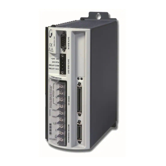
Gemini GV Series
Digital Servo Drives
D C
4 V
+ 2
n
R t
V
2 4
O M
Y C
.
L A
. O
R E
Y N
L A
R E
O
R V
r
o t o
S E
u m
U
m p
C o
V
W
+
U S
V B
N I
M I
G E
0
H 4
-
U S
V B
L 3
L 2
L 1
a y
r
e m
w e
a g
p o
o lt
e r
s v
a f t
o u
t e s
a r d
in u
a z
8 m
: H
IN G
t o
R N
W A
Advertisement
Table of Contents

Related Manuals for Parker Gemini GV Series


Summary of Contents for Parker Gemini GV Series
- Page 1 Effective: December 1, 2001 o t o N .O – N .O o lt a f t r v o t e s a r d in u IN G /1 2 3 /6 Gemini GV Series Digital Servo Drives...
- Page 2 Since Parker Hannifin constantly strives to improve all of its products, we reserve the right to change this user guide and software and hardware mentioned therein at any time without notice.
-
Page 3: Table Of Contents
www.comoso.com Table of Contents ..............................5 HANGE UMMARY 1 – I ..........................7 HAPTER NTRODUCTION Gemini Products—Overview .............................. 8 Compatible Compumotor Products ........................... 10 2 – I ..........................11 HAPTER NSTALLATION Checking Your Shipment ..............................12 “Express Setup” Overview ..............................12 Step 1 – Connecting the Motor ............................14 Step 2 –... - Page 4 www.comoso.com Product Type : Gemini Family of Drives, GV-nnnn Including, but not limited to : GV-L3n, GV-U3n, GV-U6n, GV-U12n, GV-H20n, GV-H40n , GPDM When installed in accordance with this installation guide, the above products have been demonstrated to be in compliance with the requirements of directives •...
-
Page 5: Change Summary
www.comoso.com Change Summary Gemini GV Hardware Installation Guide Revision E December 1, 2001 The following is a summary of the primary technical changes to this document since the previous version was released. This document, part number 88-017791-01E, supersedes 88-017791-01D. GV-H40 Drive Added to Gemini Product Line Information about the Gemini GV-H40 Drive has been added throughout this Hardware Installation Guide. - Page 6 www.comoso.com added to Appendix B Using Non-Compumotor Motors. Ferrite Absorbers Recommended for GV-H20 (page 88) CHANGE: For increased product immunity and reduced product emissions, particularly with large servo motors, we now recommend that you install two clip- on ferrite absorbers. Revision D December 17, 1999 The following is a summary of the primary technical changes to this document...
-
Page 7: Chapter 1 - Introduction
www.comoso.com C H A P T E R O N E Introduction IN THIS CHAPTER • Gemini Product Overview • Compatible Compumotor Products Chapter 1 – Introduction... -
Page 8: Gemini Products-Overview
www.comoso.com Gemini Products—Overview The Gemini Series is a family of high performance digital drives. The family contains drives for both stepper and servo motors. With many models and options available, the user can choose the precise level of power and control for the application’s motion requirements. - Page 9 www.comoso.com Gemini Product Names The following table lists the meanings of letters and numbers in Gemini product names. Notice that “T” is associated with step motor products (“sTep”), and “V” is associated with servo motor products (“serVo”). Control Level: Step Motor Drives Servo Motor Drives and Controller/Drives and Controller/Drives...
-
Page 10: Compatible Compumotor Products
www.comoso.com Compatible Compumotor Products GT-nn Stepper 6K or other Compumotor indexer ±10V mode: GV-nnn Servo 6K or other Compumotor controller Step/Direction mode: 6K or other Compumotor indexer Software Motion Planner Pocket Motion Planner (version 1.2 or higher) Note: Gemini drives are not compatible with ASCII communication programs such as Motion Architect or X Language software. -
Page 11: Chapter 2 - Installation
www.comoso.com C H A P T E R T W O Installation IN THIS CHAPTER • Checking Your Shipment • Express Setup Chapter 2 – Installation... -
Page 12: Checking Your Shipment
www.comoso.com Checking Your Shipment Inspect your shipment carefully. You should have received one or more of the following: Gemini Drives GV-L3n (“n” can be E (for Encoder) or R (for Resolver)) GV-U3n GV-U6n GV-U12n GV-H20n GV-H40n Ship Kit Items The following ship with the drive: Part Part Number Gemini GV Quick Reference Guide... - Page 13 www.comoso.com In the express setup, we will give procedures for the following steps: Connecting the motor to the drive (with no load attached) Connecting AC power to the drive Establishing communications and configuring the drive for autorun Connecting a controller, enabling the drive, and observing the motor turn Information you may need for final installation will be presented in Chapter 3 Configuration, in Chapter 4 Special Features, in Appendix A Specifications, and in the separate Gemini Motor Reference Manual.
-
Page 14: Step 1 - Connecting The Motor
www.comoso.com System Overview In this express setup procedure, we will give instructions for a Compumotor system—Gemini drive with Compumotor motor, Compumotor cables, and Compumotor 6K controller. If you use non-Compumotor equipment, try to follow along and perform the steps in the Express Setup procedure; consult Appendix A Specifications for additional information you may need. - Page 15 www.comoso.com Connecting the Motor Cable Connect the MS connector on the motor cable to the mating connector on the motor. (If you use a non-Compumotor motor, see Appendix B for information.) Remove the clear plastic cover from the drive terminals. Connect the motor cable’s green/yellow wire to the drive terminal with the symbol.
-
Page 16: Step 2 - Connecting Ac Power
www.comoso.com Step 2 – Connecting AC Power Acceptable ranges of AC input voltage are listed below for each drive : Drive AC Input Range GV-L3n 95 – 132VAC GV-U3n/U6n/U12n 95 – 264VAC GV-H20n 165 – 264VAC [single phase (1∅) or three phase power (3∅)] GV-H40n 165 –... - Page 17 www.comoso.com Fuses Fuses Fuses Fuses VBUS– 165VAC – L2/N 264VAC 3∅ 95 – 132VAC 95 – 264VAC 165 – 264VAC, 1∅ GV-L3n at GV-U3n/6n/12n GV-H20n at 208/ GV-H20n/H40N at 120VAC at 120/240VAC 240VAC 1-phase 208/240VAC 3-phase GV-L3/U3/U6/U12/H20: GV-H40: Drive terminals: #8 (M4).
-
Page 18: Step 3 - Configuring The Drive
www.comoso.com Step 3 – Configuring the Drive Gemini drives have no DIP switches or potentiometers for configuration. You will use software tools to communicate with the drive and configure drive settings. Configuration Software Two software programs are located on the Motion Planner CD-ROM. Motion Planner runs on a personal computer (PC). - Page 19 www.comoso.com Configuring the Drive Choose one of the columns below, based upon which software program you are using—Motion Planner, or Pocket Motion Planner—and follow the procedure to configure your drive. NOTE: If this is not the first time the drive has been configured, issue an RFS command (Return to Factory Settings) from the terminal emulator, before performing the following procedures.
-
Page 20: Step 4 - Connecting The 6K Controller
www.comoso.com Step 4 – Connecting the 6K Controller Connecting the 6K Controller and Enabling the Drive In this section of Express Setup, you will use the 6K to enable the Gemini drive. When you issue the DRIVE1 command in Step 5, the 6K will connect the Gemini’s enable input to ground, thus enabling the drive. - Page 21 www.comoso.com Verifying Correct System Operations Choose one of the columns below, based upon which controller you are using—6K or non-6K—and follow the procedure to verify correct system operations. Verifying Correct System Operations Verifying Correct System Operations with a 6K Controller without a 6K Controller Verify that the drive is enabled.
-
Page 22: What's Next
www.comoso.com What’s Next? This chapter has given you information and instructions for performing an Express Setup. The following list explains the steps you should take to complete your installation, and indicates where to find additional information for each of those steps. -
Page 23: Chapter 3 - Configuration
www.comoso.com C H A P T E R T H R E E Configuration IN THIS CHAPTER • Configuration • Tuning Procedures Chapter 3 – Configuration... -
Page 24: Configuration
www.comoso.com Configuration You can configure the Gemini drive’s settings for optimum system performance. For most of these settings, configuration is optional—if you do nothing, the drive will use default values the very first time it powers up. If you change any settings, the new settings are saved automatically. - Page 25 www.comoso.com DMTLMN minimum line-to-line inductance DMTLMX maximum line-to-line inductance DMTD motor damping DMTRWC motor thermal resistance (winding to case) DMTTCM motor case (and heatsink) thermal time constant DMTTCW motor winding thermal time constant DPWM PWM switching frequency DMTMAX motor maximum temperature SHALL Hall sensor orientation System Settings...
- Page 26 www.comoso.com Input/Output (I/O) Settings The I/O settings configure the drive’s three digital inputs, three digital outputs, and two analog monitors. Digital Inputs Command Description Options: hard limit disable hard limits disabled negative limit only positive limit only both hard limits enabled INLVL input sense active high or active low...
- Page 27 www.comoso.com Tuning Settings Tuning settings are divided into two groups: primary and advanced. Tuning can be done in torque, velocity, or position mode. Tuning procedures for each of these modes are presented below. Relevant commands are: Primary Tuning – Torque Mode Commands Command Description Options: DIBW...
-
Page 28: Tuning Procedures
www.comoso.com Tuning Procedures During the Express Setup procedure in Chapter 2 Installation, the drive uses default values for tuning parameters, based upon the motor information you entered. That procedure assumes that the motor is unloaded. In the following tuning procedures, you will enter in system information that will characterize the load on the motor. - Page 29 www.comoso.com Torque Mode Tuning Procedure Primary Tuning Procedure Disable the drive. Configure the drive for torque tuning mode (DMODE15). In this mode, the drive commands a bipolar step change in current, proportional to the motor’s continuous current rating, at a 10 Hz repetition rate. (The drive will ignore torque commands on its command input terminals which may come from an external device, such as a servo controller.) Configure ANALOG MONITOR A to show commanded d-axis current...
-
Page 30: Velocity Mode Tuning
www.comoso.com Velocity Mode Tuning For most applications, the default tuning parameters for velocity and position modes are set to provide good, stiff motor shaft performance for a given load setting. With the default tuning parameters set in the Express Setup procedure, you need only set the system load-to-rotor inertia ratio and your system will be tuned. -
Page 31: Position Mode Tuning
www.comoso.com Connect a second channel of your oscilloscope to the drive’s ANALOG MONITOR B (pin 22). Connect your oscilloscope’s ground to the drive’s ANALOG GROUND (pin 25). Adjust your oscilloscope to display commanded versus actual velocity. (The analog monitors can be scaled, in percent, with the DMONAS and DMONBS commands. You may need to set these to large values if the maximum velocity is small.) Enable the drive and observe your system’s response. - Page 32 www.comoso.com Position Mode Tuning Procedure Primary Tuning Procedure Disable the drive. Configure the drive for position tuning mode (DMODE17). In this mode, the drive commands an alternating 1/4 revolution step change in position at a one second repetition rate. Enable the drive and observe your system’s response. (If necessary, you can connect an oscilloscope as described in Advanced Tuning below.) Ringing or an oscillating response indicates that the position loop bandwidth is too high.
-
Page 33: Filter Adjustments
www.comoso.com After you achieve a satisfactory system response, reconfigure the drive for position mode (DMODE6, DMODE7, or DMODE8). This completes the advanced tuning procedure. If ringing or oscillations persist, and do not seem to be affected by the above adjustments, you may need to use notch filters or lead/lag filters. See the Filter Adjustments procedure below. - Page 34 www.comoso.com 12. Adjust the Q of the filter (DNOTAQ command) until ringing is controlled, using the following guidelines: • Set Q as low as possible. Resonances change with load; therefore, your system will be more robust with a lower Q value. •...
-
Page 35: Chapter 4 - Special Features
www.comoso.com C H A P T E R F O U R Special Features IN THIS CHAPTER • Relay • +24VDC Keep Alive Power Connections • Multiple Drive Installations • V BUS± • Regeneration Protection and the GPDM • Aligning the Resolver •... -
Page 36: Relay Connections (Optional)
www.comoso.com Relay Connections (optional) To use the drive’s internal relay, connect your external circuit to the RELAY COM and RELAY N.O. terminals. The next drawing shows a typical application—connecting a motor brake to the relay terminals. GEMINI Drive User Supplied +24VDC +5VDC RELAY COM... -
Page 37: Multiple Drive Installations (Optional)
www.comoso.com DRIVE POWER SUPPLY VDC+ +24V DC 24V RTN VDC– RELAY COM RELAY N.O. Use twisted pair wiring +24VDC Power Input +24VDC Specifications: Input voltage range: 19.2 – 28.8 VDC Input current: 500 mA (minimum) Functions powered under +24VDC: position information (encoder or motor position counters in drive) communications diagnostics... -
Page 38: Regeneration Protection
www.comoso.com ± Connecting V Bus : Sharing the Power Bus (optional) You can connect the power buses of Gemini GV-U3n/U6n/U12n/H40n drives in parallel, through the V BUS+ and V BUS- terminals. With the buses connected in parallel, regenerated energy from one drive will be used by the other drives. (Do not connect GV-H20n drives in parallel to each other or to other Gemini drives.) WARNING V BUS+ and V BUS- terminals are at hazardous voltages when power is applied to... - Page 39 www.comoso.com Regeneration with GV-L3n/H20n/H40n Gemini GV-L3n/H20n/H40n drives have internal circuitry to protect them from regeneration—energy from the load during deceleration. Excessive regeneration can cause either of two faults: • Overvoltage Fault (see Overvoltage Protection in Appendix A Specifications ) • Regeneration Fault (if regeneration occurs for an extended period of time) Specifications for regeneration protection are: Maximum...
- Page 40 www.comoso.com the fault and reset itself within 10 seconds (an overtemperature fault may take longer to clear). When it resets itself, the GPDM will illuminate its green LED; the GPDM is then again ready to dissipate regenerated energy. If regeneration continues while the GPDM is in a faulted state, the drive may experience an overvoltage fault.
- Page 41 www.comoso.com The next figure shows a typical installation. GV-U3n/6n/12n GV-U3n/6n/12n GV-U3n/6n/12n VBUS+ VBUS+ VBUS+ VBUS+ VBUS+ VBUS– VBUS– VBUS– VBUS– VBUS– L2/N L2/N L2/N fuses Connect 2nd GPDM, if necessary Use a single point safety earth GPDM Connections The next figure shows GPDM dimensions. 2.75 (70) (152)
-
Page 42: Aligning The Resolver (Optional)
www.comoso.com Aligning the Resolver (optional) Resolvers on Compumotor motors are aligned at the factory. Ordinarily, no further alignment is required. However, you may wish to align the resolver if you suspect the resolver is misaligned, or if you are using a non-Compumotor motor. A Note About Resolver Speed Resolver speed describes the relationship between resolver electrical revolutions and shaft mechanical revolutions. - Page 43 www.comoso.com Method 2 – Finding an Unknown Offset Angle Use this method if you do not know your resolver’s offset angle. Disconnect the load from the motor shaft. The shaft should be free to rotate. Verify correct motor wiring. See the Gemini Motor Reference Manual for wiring information for Compumotor motors.
-
Page 44: Rs-232/485 Communications
www.comoso.com RS-232/485 Communications The Gemini drive has a single serial port marked, “ ,” on the front of the RS-232/485 unit. In the following this port will be referred to as the COM port. The Gemini drive uses a binary language for communication; it does not use ASCII. To enable 6000 ASCII level communication in a terminal mode, the Gemini uses a translator utility in Pocket Motion Planner and in the CommServer (for use with Motion Planner). -
Page 45: Rs-232 Communications
www.comoso.com End of Line Terminating Characters ERRBAD Error Prompt ERRLVL Error Detection Level ERROK Good Prompt • The baud rate for the Gemini is set at 9600. Future releases of Gemini firmware will offer additional baud rate choices. Check the Compumotor web site (www.compumotor.com) for information on new software releases. - Page 46 www.comoso.com address for each unit. The ADDR command automatically configures unit ad- dresses for daisy chaining. This command allows up to 99 units on a daisy chain to be uniquely addressed. Sending ADDRi to the first unit in the daisy chain sets its address to be (i). The first unit in turn transmits ADDR(i + 1) to the next unit to set its address to (i + 1).
-
Page 47: Rs-485 Communications
www.comoso.com Step 3 Now that you have verified that the daisy chain is set up properly, you can use the various Pocket Motion Planner and Motion Planner tools to configure and monitor all units on the daisy chain. RS-485 Communications Pin Out for 4-Wire RS-485 Communications: Pin Description (also called RD B) -
Page 48: Updating The Drive's Operating System
www.comoso.com the ADDR command, you must address each unit individually before it is con- nected on the multi drop. For example, given that each product is shipped configured with address zero, you could set up a 4-unit multi-drop with the commands below, and then connect them in a multi drop: Connect the unit that is to be unit #1 and transmit the Ø_ADDR1 command to it. -
Page 49: Chapter 5 - Troubleshooting
www.comoso.com C H A P T E R F I V E Troubleshooting IN THIS CHAPTER • LED Status • Software Commands for Troubleshooting • RS-232/485 Troubleshooting • System Problems Chapter 5 – Troubleshooting... - Page 50 www.comoso.com Troubleshooting Guidelines If your system is not functioning properly, first try these steps. First Troubleshooting Steps: • Is the left LED illuminated? If not, look for problems with AC power. Also see System Problems at the end of this chapter. •...
- Page 51 www.comoso.com Save the Configuration File Since further troubleshooting steps may change the drive configuration, you should upload the current drive configuration file and save it to your PC, in case you need it for future reference. Reconfigure the Drive To verify proper configuration, you may wish to reconfigure the drive. Pay particular attention to selecting proper configuration settings for the motor that you have installed, as motor configuration problems can cause a variety of errors.
- Page 52 www.comoso.com TASX – Transfer Extended Axis Status The TASX command returns the axis status conditions. It reports more informa- tion than the TAS command, and is helpful for identifying which faults occurred. It returns a 32 bit response: 1 = Yes; Ø = No. (Use the TASXF command for a text-based status report).
- Page 53 www.comoso.com RS-232/485 Communication Problems If you cannot establish RS-232 or RS-485 communications, the next sections give instructions for procedures to help isolate problems. Testing the COM Port Install and launch either Motion Planner or Pocket Motion Planner. See Chapter 2 Installation for information about using these software tools.
- Page 54 www.comoso.com Testing the Cable Use the following two procedures to test your null modem cable, and verify that it is working properly. “Loop Back” Test Connect one end of your RS-232 cable to your PC, palm PC, or HPC. Disconnect the other end of the cable from the drive.
- Page 55 www.comoso.com System Problems If your Gemini drive is functioning properly, other parts of your system may be causing problems. It may be difficult to identify where the problem is coming from. To diagnose system problems, we recommend that you first have the drive perform its autorun function.
- Page 56 www.comoso.com Motor Resolver Resolvers on Compumotor motors are aligned at the factory. Ordinarily, no further alignment is necessary. However, if you suspect that the resolver has been altered and is out of alignment, you can follow the alignment procedure in Aligning the Resolver, located in Chapter 4 Special Features.
-
Page 57: Appendixa - Specifications
www.comoso.com A P P E N D I X A Specifications IN THIS CHAPTER • Gemini Drive Specifications • Input/Output Specifications • Dimensions • Protective Circuits • Cable Specifications Appendix A – Specifications... -
Page 58: Power Specifications
www.comoso.com Power Specifications +24VDC Input Power (Optional “Keep Alive” Power) Input voltage range: 19.2 – 28.8 VDC Input current: 500 mA (minimum) AC Input Power Drive AC Input Voltage GV-L3n 95VAC – 132VAC, 1-phase, 50/60 Hz GV-U3n 95VAC – 264VAC, 1-phase, 50/60 Hz GV-U6n 95VAC –... -
Page 59: Interface/Communication
www.comoso.com Environmental Specifications GV-L3n; GV-U3n/U6n/U12n; GV-H20n (with < 25W regen); GV-H20n (with GV-H40n <100W regen) Operating Temperature: Still Air: 45°C (113°F) 35°C (95°F) Moving air: 50°C (122°F) 40°C (104°F) Minimum: 0°C (32°F) 0°C (32°F) Storage Temperature: -40°C – 85°C (-40°F – 185°F) Humidity: 0 –... -
Page 60: Inputs And Outputs
www.comoso.com Inputs and Outputs This section describes all inputs and outputs (I/O) located on the 50 pin DRIVE I/O connector. Not all are required for your system to operate. The next drawing summarizes which are required, and which are optional. Required Optional Complete Pinout... - Page 61 www.comoso.com Command Input (required) The Gemini servo drive can accept several types of command input signals. Use the DMODE command to configure your drive to accept either ±10V or a pulse input (step/direction, clockwise/counterclockwise, or encoder). DRIVE I/O Connector Internal Connections 250 mA maximum source Encoder +5...
- Page 62 www.comoso.com Enable Input (required) To enable the drive and energize the motor, you must connect the enable input (pin 1) to digital ground (pin 2). The next drawing shows the internal circuit. DRIVE I/O Connector Internal Connections Inputs internally pulled up to +24V, unless you connect an external 5 –...
- Page 63 www.comoso.com Digital Inputs (optional) The Gemini drive has three digital inputs. Their functions are: Input 1 Positive Limit Input Input 2 Negative Limit Input Input 3 User Fault Input By default, these are +24VDC sourcing inputs. You can use VINref (pin 26) to change the switching voltage level.
- Page 64 www.comoso.com Digital Outputs (optional) The Gemini drive has three digital outputs. Their functions are: Output 2* Drive Fault Output Output 3* At Limit Output 4* Position Error Output * For compatibility with other Compumotor products, the outputs are numbered 2, 3 and 4, rather than 1, 2 and 3.
- Page 65 www.comoso.com The encoder output circuit is shown in the next drawing. Internal Connections DRIVE I/O Connector AM26LS31 From DSP 14 Encoder Out A+ (or passed through if required conditions met) 15 Encoder Out A- AM26LS31 16 Encoder Out B+ From DSP 17 Encoder Out B- (or passed through if 18 Encoder Out Z+...
-
Page 66: Feedback Devices
www.comoso.com Feedback Devices This section describes inputs for encoder feedback, resolver feedback, motor thermal switch, and Hall effects located on the drive’s 26 pin MOTOR FEED- BACK connector. The next drawing shows the pinout of the connector. Connector Pinout Cos– Thermal Switch Thermal Switch Cos+... - Page 67 www.comoso.com Encoder If you use a motor with encoder feedback, connect your encoder to pins 1 – 10, as shown in the figure below. MOTOR FEEDBACK Connector Internal Connections 250 mA maximum: Encoder +5V and Hall +5V combined Encoder +5V Encoder +5V Encoder Ground Encoder Ground...
- Page 68 www.comoso.com Motor Thermal Switch Connections (optional) Connect your motor’s thermal switch wires to pins 12 and 13 on the MOTOR FEEDBACK connector. The drive checks for electrical continuity between pins 12 and 13. This continuity is usually provided by a normally-closed thermal switch mounted on the motor. If the motor overheats and the thermal switch opens, the loss of continuity triggers protection circuitry in the Gemini drive.
-
Page 69: Dimensions
www.comoso.com Dimensions Drive Dimensions 2.75 6.00 3x clearance (70) (153.0) for #8 or M4 mounting screws 1.38 0.58 0.16 5.40 (35) (14.7) (4.1) (138.0) (203.2) 7.75 (196.9) (177.8) Dimensions in inches (mm) 1.00 0.88 (25.4 ) (22.2) Fin Height Overall Width Product inches (mm) inches (mm) - Page 70 www.comoso.com (127) 2.75 6.00 3x clearance (70) (153.0) for #8 or M4 mounting screws 2.25 1.38 0.58 0.16 5.40 (57.2) (35) (14.7) (4.1) (138.0) (251.5) 9.63 (244.5) (226.1) Dimensions in inches (mm) 1.00 0.88 (25.4 ) (22.2) Dimensions – GV-H20n Gemini GV Hardware Installation Guide...
- Page 71 www.comoso.com 4.88 8.50 3x clearance (124) (216) for 1/4" or M6 3.82 mounting screws (97.1) 7.68 2.44 0.83 0.23 (195) (62) (21) (5.7) 6.53 Back of (165.7) flange masked from paint 12.88 (327) 12.500 (317.5) 11.40 (289.6) Back of flange Dimensions in inches (mm) 2.500 1.19...
- Page 72 www.comoso.com Panel Layout Dimensions NOTE: Provide proper spacing to maintain minimum clearance between drives. Panel Layout: 1.00 GV-L3n (25.4 ) GV-U3n Minimum Clearance GV-U6n GV-U12n 1.00 (25.4 ) Minimum Clearance 1.00 (25.4 ) Minimum Clearance 1.00 1.00 0.50 (25.4 ) (25.4 ) (12.7) Minimum...
- Page 73 www.comoso.com Panel Layout: GV-H20n (shown below) GV-H40n NOTE: Provide proper spacing to maintain minimum NOTE: Vertical spacing clearance between drives. between drives: 8 in. (200 mm) for GV-H40 0.50 operating at full power; (12.7) 6 in. (150 mm) for GV-H20 Minimum operating at full power;...
-
Page 74: Protective Circuits
www.comoso.com Protective Circuits Short Circuit Protection The Gemini drive has an internal circuit that protects it from short circuits between one motor terminal to another (phase to phase), or from any motor terminal to earth. A short circuit fault is a latched fault. Short circuit fault caused by: Phase to phase short circuit Phase to earth short circuit... - Page 75 www.comoso.com Undervoltage Protection The Gemini drive’s undervoltage protection circuit monitors AC input voltage. If the voltage falls below 75VAC while the drive is operating (85VAC for GV-H20), the drive issues an undervoltage fault and turns off power to the motor. Undervoltage protection has the following features: Threshold Voltage: Voltage falling below 75VAC trips fault...
-
Page 76: Cable Specifications
www.comoso.com Cable Specifications This section contains specifications for Compumotor cables and cabling accesso- ries you can use with Gemini drives. CE Cables Many Compumotor cables are CE Cables. If installed according to instructions in Appendix C – Regulatory Compliance: UL and CE, these cables are designed to aid the user in gaining European Compliance, and are thus an integral part of a CE system solution. - Page 77 www.comoso.com Step and Direction Command Cable If you operate the drive in step and direction (position) mode, use this cable to connect the Gemini drive to a Compumotor 6K controller CE Cable: Part Number 71-016966-10 10 ft. (3 m) in length Non-CE Cable: Part Number 71-019862-04 4 ft.
- Page 78 www.comoso.com Compumotor 6250, AT6n50 Connections The next drawing shows connections to a Compumotor 6250 or AT6n50 control- ler. 6250, AT6n50 Gemini Brown Brown CMD+ (Command+) CMD+ (Command+) White/Brown White/Brown CMD– (Command –) CMD– (Command –) White/Violet White/Violet SHTNO (Shutdown Normally Open) Enable White/Gray White/Gray...
- Page 79 www.comoso.com Gemini 50 Pin Connector to 50 Pin D-Connector Cable Use this cable to connect the Gemini drive’s 50 pin DRIVE I/O connector to the 50 pin D-connector on the Gemini 50 pin breakout module (GEM-VM50). CE Cable: Part Number 71-016945-03 This cable has the same pinout and color code as the CE version of the flying lead cable;...
- Page 80 www.comoso.com Gemini GC-26 and GC-50 Connectors Two breakout modules are available that connect directly to the Gemini’s MOTOR FEEDBACK and DRIVE I/O connectors. NOTE: These modules are recommended for system prototyping only—not for permanent installation. Description: Part Number: 26 pin Connector/Breakout Module GC-26 50 pin Connector/Breakout Module GC-50...
-
Page 81: Motors
www.comoso.com A P P E N D I X B Using Non-Compumotor Motors IN THIS CHAPTER • Commands for Motor Configuration • Motor Requirements Appendix B – Non-Compumotor Motors... - Page 82 www.comoso.com Using Non-Compumotor Motors If you use a non-Compumotor motor, you must configure the drive for your motor by setting values for all commands in the following table. Also see the Motor Parameters table on the Motion Planner CD-ROM for examples of recommended drive configuration settings for Compumotor motors.
- Page 83 www.comoso.com As reported by THALL, is the Hall state sequence [1, 5, 4, 6, 2, 3, 1 ... ] as the motor turns clockwise? (Clockwise means TPE is increasing; it is also the direction the motor turns in DMODE13.) IF NOT: see Problem #4, below. Does TASX report a Hall fault each time the drive is enabled (DRIVE1), even though the Hall state sequence is correct? IF YES: see Problem #4, below.
- Page 84 www.comoso.com Connect motor wires U and V and slowly apply a positive voltage with respect to W. See the previous drawing. WARNING This procedure could damage the motor. Slowly increase the voltage until the motor moves. Do not exceed the rated current. If THALL reports a value of 1, 2 or 4, change SHALL from either 0 to 1 or from 1 to 0.
-
Page 85: Appendixc - Regulatory Compliance : Ul And Ce
www.comoso.com A P P E N D I X C Regulatory Compliance: UL and CE IN THIS CHAPTER • Installation Instructions • Installation Guidelines • System Installation Techniques Appendix C – Regulatory Compliance: UL and CE... - Page 86 www.comoso.com Regulatory Agencies The Gemini family of products is designed to meet the requirements of global regulatory agencies. Gemini products have shown compliance with the regulatory agencies in the following list. The list also shows additional steps users must take to ensure compliance.
- Page 87 16 amp filter – part number 47-017900-01 +24VDC Power Supply If you use the +24VDC power supply Parker Compumotor offers for sale (PS-60W), no additional filter is required on the +24VDC mains. If you use another manufacturer’s +24VDC power supply, it should be CE marked for safety and electromagnetic compatibility.
- Page 88 www.comoso.com Installation Guidelines Gemini products are made available under “Restricted Distribution” for use in the “Second Environment” as described in EN 61800-3: 1996, page 9. Cabinet Mounting For Electromagnetic Compatibility, cabinet mounting is not required. However, Gemini drives have high voltage terminals—for safety purposes, the drive must not be user accessible during normal operation.
- Page 89 www.comoso.com R-Clamp Remove outer jacket only. Do not cut braid. Bulkheak Clamshell Clamp Bulkheak Clamshell Clamp Enclosure Panel Enclosure Panel Cable Cable 360 ° Bonding Techniques The following clamps and clamp kits are available from Compumotor. Clamp Type: Compumotor Part Number: R-Clamp 58-016050-01 R-Clamp Kit (10 per)
- Page 90 www.comoso.com System Installation If you mount the Gemini drive in an enclosure, terminate cable braids (screens) at the entrance of the enclosure. However, the motor braid must be returned to the drive’s saddle clamp (GV-H20n/H40n: R-Clamp on front of drive), not any other location.
- Page 91 www.comoso.com GV-H20n Mount to earthed Limits Drive metal panel. Remove paint from flange and Bond braid to earthed panel. mounting locations. Use R-clamp or bulkhead clamshell clamp. (See 360° bonding drawing.) RS-232/485 Cable VDC+ +24VDC VDC– Power Supply Ferrite Twisted at 3 twists absorber minimum per inch (25 mm)
- Page 92 www.comoso.com Mount to earthed GV-H40n metal panel. Remove Drive paint from flange and mounting locations. Limits Bond braid to earthed panel. Use R-clamp or bulkhead clamshell clamp. (See 360° bonding drawing.) RS-232/485 Cable VDC+ +24VDC VDC– Power Ferrite Supply absorber Twisted at 3 twists GEM-VM50 minimum per...
-
Page 93: Index
www.comoso.com Index Symbols configuration status 52 GFB-KIT 26 pin connector kit 80 configure drive 18 GPDM 39 +24VDC keep alive power 36, 58 connector +24VDC power input 37 Drive I/O 60, 66 ±10V command inputs 61 Motor Feedback 66 Hall effects 68 26 pin breakout module 80 RS-232/485 44 26 pin connector kit 80... - Page 94 www.comoso.com naming system 9 serial port 44 non-Compumotor motor 82 sharing power bus 38 notch filter 33 ship kit 12 null modem cable short circuit protection 74 troubleshooting 54 software commands 51 wiring and color code 79 specifications 58 numbering system 9 standards 59 step and direction cable 77...
- Page 95 www.comoso.com RS-232/485 Connector – Configuration Port: see page 44 50 Pin DRIVE I/O Connector – see page 60 To configure all drive parameters, connect a PC or HPC to this port. Use Motion Planner or Pocket Motion Planner for drive Gemini GV configuration.
Need help?
Do you have a question about the Gemini GV Series and is the answer not in the manual?
Questions and answers