Sign In
Upload
Manuals
Brands
Parker Manuals
Servo Drives
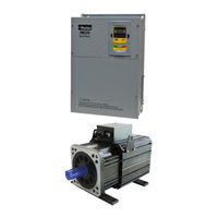
IM20-S0300T3E7 F2D2B1R3CP3
Parker IM20-S0300T3E7 F2D2B1R3CP3 Manuals
Manuals and User Guides for Parker IM20-S0300T3E7 F2D2B1R3CP3. We have
1
Parker IM20-S0300T3E7 F2D2B1R3CP3 manual available for free PDF download: Product Manual
Parker IM20-S0300T3E7 F2D2B1R3CP3 Product Manual (74 pages)
Servo System for Injection Molding application
Brand:
Parker
| Category:
Servo Drives
| Size: 3 MB
Table of Contents
Table of Contents
3
Summary
6
Product Check
6
Servo Drive Nameplate
6
Servo Motor Nameplate
6
Servo Drive Naming Rule
7
Servo Motor Naming Rule
8
Appearance
10
Precautions
10
Installation Instructions
10
Wiring Instructions
10
Operation Instructions
10
Maintenance
10
Disposal
10
Servo System Specifications and Model Selection
11
Servo Drive Specifications and Parameters
11
Specifications
11
Servo Drive Parameter and Equipment Model Selection
11
Wiring and Ferrite Core Recommended
12
Servo Motor Specifications
13
Servo Motor Technical Specification
13
Servo Motor Main Parameter
13
Recommended Configuration
15
Servo Drive, Motor and Oil Pump Selection
15
Combined-Configuration
16
Installation
18
Servo Drive Installation
18
Servo Drive Structure
18
III. Installation
18
Servo Motor Installation
19
Braking Unit and Braking Resistor
20
System Wiring
22
System Construction
22
IV. System Wiring
22
Connection
23
Main Circuit Connection
24
Functions of Control Terminals
24
Analog Channel Switchover
26
Keypad Panel
27
Panel Illustration
27
Panel Operation
27
Parameters Setting
27
Function Codes Switchover In/Between Code-Groups
27
Panel Display
29
Function Parameters
30
Basic Parameters
30
Running Control Mode
30
Multifunctional Input and Output
32
Analog Input and Output
34
Braking and Protection
35
Motor Parameters
37
Pressure Control Parameters
39
Multiple Pump Combined Control
42
Injection Molding Machine Debugging
46
Check the Oil Channel and Circuit Wiring
46
Servo Motor Parameter
46
Analog Adjust
46
Max Pressure Setting
47
FA23, F114, F115 Setting
47
Closed-Loop Operation
47
Trouble Shooting
48
VII. Trouble Shooting
48
Maintenance
53
Periodic Checking
53
Replacement of Wearing Parts
53
Storage
53
VIII. Maintenance
53
Appendix 1 Zoom Table of Function Code
54
Appendix 2 Expand Card
65
Appendix 3 Servo Motor Structure Diagram
66
Appendix 4 Communication (V1.0)
70
Advertisement
Advertisement
Related Products
Parker IM20-S0370T3E7 F2D2B1R3CP3
Parker IM20-S0150T3E5 F2D2B1R3CP3
Parker IM20-S0185T3E6 F2D2B1R3CP3
Parker IM20-S0040T3E4 F2D2B1R3CP3
Parker IM20-S0220T3E6 F2D2B1R3CP3
Parker IM20-S0450T3C4 F2D2B1R3CP3
Parker IM20-S0055T3E4 F2D2B1R3CP3
Parker IM20-S0550T3C5 F2D2B1CP3
Parker IM20-S0750T3C5 F2D2B1CP3
Parker IM20-S0900T3C6 F2D2B1CP3
Parker Categories
Controller
Control Unit
Industrial Equipment
Dryer
DC Drives
More Parker Manuals
Login
Sign In
OR
Sign in with Facebook
Sign in with Google
Upload manual
Upload from disk
Upload from URL