
Related Manuals for Parker PSD1-SW1200


Summary of Contents for Parker PSD1-SW1200
- Page 1 192-011006N8 PSD1 Installation Guide Parker Servo Drive 192-011006N8 Servo Drives 2019-07 Up from release R1.7.1 Installation instructions 1 (109) 192-011006N8 2019-07 09.10.19 09:27...
- Page 2 Parker Hannifin Manufacturing Germany GmbH & Co KG - Sitz: Bielefeld - Amtsgericht: Bielefeld HRA 15699 Partner liable to unlimited extent: Parker Hannifin GmbH, Sitz Bielefeld, Amtsgericht Bielefeld HRB 35489 Geschäftsführung der PARKER Hannifin GmbH: Dr.-Ing. Hans-Jürgen Haas, Kees Veraart, Chairman of the board: Dr.-Ing. Gerd Scheffel Italy: Parker Hannifin Manufacturing Srl Electromechanical &...
-
Page 3: Table Of Contents
2.11 Before commissioning the drive, please observe the following: ....... 25 3. PSD: PSD -Parker Servo Drive - Overview ............26 4. Installation of the individual drive PSD1-S ............27 Before commissioning the drive, please observe the following: ....... 27 Mounting and dimensions .................... - Page 4 What is necessary and where to find it? 5. Installation of the multi-axis system PSD1-M ............. 40 Before commissioning the drive, please observe the following: ....... 41 Mounting and dimensions ....................41 5.2.1. Mounting and dimensions PSD1-M size 1 ..............42 5.2.2.
- Page 5 192-011006N8 PSD1 Installation Guide SMH Servo Motors with HIPERFACE DSL® - Feedback ..........81 7.1.1. Order code of motor cable ....................82 EMC measures ........................ 82 7.2.1. Mains filter ........................82 7.2.2. Motor output chokes ....................... 84 Line choke ........................87 7.3.1.
-
Page 6: What Is Necessary And Where To Find It
What is necessary and where to find it? 1. What is necessary and where to find Software Tool, PSD ServoManager Field Bus Files, Downloads under http://solutions.parker.com/psd_support CE declaration of http://solutions.parker.com/psd_support compliance 6 (109) 192-011006N8 2019-07 09.10.19 09:27... -
Page 7: Introduction
• Before commissioning the drive, please observe the following: ..........25 Device assignment This manual is valid for the following devices: • PSD1-SW1200 (2 A) • PSD1-M_2220 (2 A + 2 A) • PSD1-M_3222 (2 A + 2 A + 2 A) •... -
Page 8: Type Identification Plate Psd1-M
Introduction Type identification plate PSD1-M The present device type is defined by the type specification plate (on the housing): Order code of the device Serial Number Input voltage Input Current UL certification Output voltage Output current Output frequency IP Rating 8 (109) 192-011006N8 2019-07 09.10.19 09:27... -
Page 9: Order/ Type Code Psd
192-011006N8 PSD1 Installation Guide Order/ type code PSD Ordering example PSD1 Drive family PSD1 Parker Servo Drive Device type Stand-Alone 230 VAC Multi axis 400 VAC Mounting type Wall mounting Cold plate* IP20 push through Device type 1 performance level... -
Page 10: Packaging, Transport, Storage
Introduction • The device might be destroyed what could result in fire. • The device corresponds to EN 61800-3, i.e. it is subject to limited sale. The device can emit disturbances in certain local environments. In this case, the user is liable to take suitable measures. -
Page 11: For Safety Use
192-011006N8 PSD1 Installation Guide For Safety Use In this chapter you can read about: • Explanation of the safety instructions ..................11 • Working safely / qualification ....................11 • General hazards ........................11 • Special dangers ........................11 • Cautionary Markings ......................... 12 •... -
Page 12: Cautionary Markings
Introduction • Check that all live terminals are secured against contact. Dangerous voltages up to 850V occur. • Do not short-circuit the DC power voltage. CAUTION: Risk of electric shock Caution - Risk of electric shock! Before wiring or loosening electrical connections please observe the following: •... -
Page 13: Responsibility
192-011006N8 PSD1 Installation Guide • Provide protection and/or additional safety systems in order to prevent personal injury and material damage. Always care for sufficient ventilation. • All control and signal terminals guaranty safe extra-low voltages (SELV), i.e. they are protected by a double isolation. Make sure the complete external wiring is approved for the highest system voltage. - Page 14 Introduction Contact protection mating plug In order to ensure contact protection, all mating plugs must be present on the device connections even if they are not wired. Instructions for this manual Please respect the specifications of the manual resp. of the help function, especially the technical characteristics (mains connection, circuit breakers, output data, ambient conditions,...).
- Page 15 Use only with aligned controller (to avoid control loop oscillation). 2.10.1.12 Accessories Make sure to use only the accessories recommended by Parker. Notes on the use in domestic environments 2.10.1.13 This is restricted operation category product according to EN 61800-3. This product can cause high-frequency disturbance in domestic areas.
-
Page 16: Ce Declaration Of Conformity Psd1-M
Introduction 2.10.2. CE declaration of conformity PSD1-M 16 (109) 192-011006N8 2019-07 09.10.19 09:27... -
Page 17: Ce Declaration Of Conformity Psd1-S
192-011006N8 PSD1 Installation Guide 2.10.3. CE declaration of conformity PSD1-S 17 (109) 192-011006N8 2019-07 09.10.19 09:27... -
Page 18: Conditions Of Utilization For The Cul Certification Of Psd1-M
• Temperature rating of field installed conductors shall be at least 60°C. Do only use copper lines. Do only use the Parker cables available under Accessories (see page 81) or assemble the cables according to the specified regulations. • Control voltage supply (24 VDC) only permissible with "class 2" power supply. - Page 19 192-011006N8 PSD1 Installation Guide Data of the integrated dynamic brake module PSD1-M_P Category Specifications Maximum current Minimum resistance Mains module Max. Duty Cycle value Peak Duration 4.27 A (500 W) 2.2 % (@60 s) PSD1-M_P010 28.8 A 27 Ω 7.5 A (1500 W) 6.7 % (@60 s) 7.06 A (500 W) 0.82 % (@60 s)
- Page 20 Introduction Tightening torque 0.22 ... 0.25 Nm 1.95 ... 2.21 Lb.in Mains module X40: Ballast resistor up to AWG10 up to 6 mm Tightening torque 0.46 ... 0.57 Nm (M3) 4 ... 5 Lb.in X41: Mains connector up to AWG10 PSD1-M_P010 up to 6 mm Tightening torque...
-
Page 21: Conditions Of Utilization For The Cul Certification Of Psd1-S
192-011006N8 PSD1 Installation Guide 24 VDC GND 24 VDC DC power supply bus - Protective earth DC power supply bus + Connecting protective earth Connect protective earth via a copper wire of minimum 10 mm by means of the provided screws at the bottom of the PSD1M (axis controller) and of the mains module PSD1-M_P: 2.10.5. - Page 22 • Use 60/75°C wires only Use Copper Conductors Only Do only use the Parker cables available under Accessories (see page 81) or assemble the cables according to the specified regulations. • Control voltage supply (24 VDC) only permissible with "class 2" power supply.
- Page 23 192-011006N8 PSD1 Installation Guide rated minimum 240 V (phase to ground), suitable for “Overvoltage Category III”, and shall provide protection for a rated Impulse withstand Voltage peak of 4 kV. 2.10.5.3 Tightening torque of the wiring terminals Connector Torque Digital I/Os Push-In 0,2 ...
-
Page 24: Current On The Mains Pe (Leakage Current)
Introduction 2.10.6. Current on the mains PE (leakage current) This product can cause a direct current in the protective lead. If a residual current device (RCD) is used for protection in the event of direct or indirect contact, only a type B (all current sensitive) RCD is permitted on the current supply side of this product . -
Page 25: Before Commissioning The Drive, Please Observe The Following
192-011006N8 PSD1 Installation Guide 2.11 Before commissioning the drive, please observe the following: • Read the safety instructions. • Make sure that all local electrical regulations are adhered to. • Inspect the device for any damages. • Inspect the device within the drive and system for loose ends, blends, grinding- or drilling chips, etc. -
Page 26: Psd: Psd -Parker Servo Drive - Overview
PSD: PSD -Parker Servo Drive - Overview 3. PSD: PSD -Parker Servo Drive - Overview 26 (109) 192-011006N8 2019-07 09.10.19 09:27... -
Page 27: Installation Of The Individual Drive Psd1-S
192-011006N8 PSD1 Installation Guide 4. Installation of the individual drive PSD1-S In this chapter you can read about: • Before commissioning the drive, please observe the following: ..........27 • Mounting and dimensions ......................27 • Connector overview PSD1-S ....................28 •... -
Page 28: Mounting And Dimensions
Installation of the individual drive PSD1-S Mounting and dimensions Ventilation: • During operation, the device radiates heat (heat dissipation). Please provide for a sufficient mounting distance below and above the device (at least 100 mm) in order to ensure free circulation of the cooling air. •... -
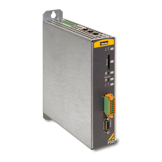
Page 29: Connector Overview Psd1-S
192-011006N8 PSD1 Installation Guide Connector overview PSD1-S In this chapter you can read about: • Front view (PSD1-S) ......................... 29 • View from below (PSD1-S) ....................... 30 • View from above (PSD1-S) ....................... 30 4.3.1. Front view (PSD1-S) CAUTION: Risk of electric shock Caution - Risk of electric shock! Before wiring or loosening electrical connections please observe the following:... -
Page 30: View From Below (Psd1-S)
Installation of the individual drive PSD1-S 4.3.2. View from below (PSD1-S) View from above (see page 30) Central ground Connect ground via ring cable lug with a 10 mm connection copper cable to central ground X51 (see page 36) To motor •... -
Page 31: View From Above (Psd1-S)
192-011006N8 PSD1 Installation Guide 4.3.3. View from above (PSD1-S) Front view (see page 29) X60 (see page 39) PC interface to configure and program servo axes X61 (see page 39) Fieldbus Interface output X62 (see page 38) Fieldbus Interface input X63 (see page 33) Terminals •... -
Page 32: X17: Digital Inputs / Outputs (Psd1-S)
Installation of the individual drive PSD1-S Status Left LED a Right LED b Status of axis (green) (ready) (red) (error) Axis energized Single flash Axis de-energized Double flash HEDA3 slave not ready Axis energized Double flash HEDA3 Slave not ready Axis de-energized Triple flash HEDA3 Master not ready... -
Page 33: Control Voltage 24 Vdc Psd1-S
192-011006N8 PSD1 Installation Guide 4.5.1. Control Voltage 24 VDC PSD1-S Category Specifications Voltage operating range 21.6 - 27.0 VDC (24 VDC -10% +12.5%) Ripple 0.5 Vss Requirement according yes (class 2 mains module) to safe extra low voltage (PELV) Electric current drain 0.5 A + Output current of digital output currents (fed via connectors X17/2, 3) + Output current of motor brakes (fed via connectors X51/1 &... -
Page 34: Mains Connection Psd1-S
Installation of the individual drive PSD1-S * The internal braking resistor is connected via bridge X63/1 and X63/2: Device protection By cyclically switching on and off the power voltage, the input current limitation can be overloaded, which may cause damage to the device. Wait at least one minute between two switching on processes! Please note! If neither a braking resistor nor a bridge are connected, the intermediate circuit... -
Page 35: X52: Motor Connection (Psd1-S)
With these motors with DSL feedback, the outputs U & V are reversed in the PSD via the motor configuration This has no effect on the wiring with Parker motor cables, you can connect them as shown in the table. -
Page 36: Output Data Psd1-S 1/3*230 Vac
Electrical connection on device (see page 46, see page 59, see page 30) We recommend the operation with Parker HIPERFACE DSL® cables! (see page Note the following, if no Parker PSD DSL motor cable is used: The internal shielding of the Hiperface DSL® signal line must be connected (braided or soldered) to the outer motor cable shielding (and thus to PE). -
Page 37: X18: Connector Assignment With Configured Resolver Feedback
192-011006N8 PSD1 Installation Guide Please observe the following if you want to disconnect the DSL lines with an additional plug: • No other lines must be wired between DSL+ and DSL-. • The DSL lines must be twisted and separately shielded. •... -
Page 38: X18: Assignment With Configured Incremental Encoder Or Analogue Hall
Installation of the individual drive PSD1-S 4.9.3. X18: Assignment with configured incremental encoder or analogue Hall Incremental encoder / analogue & digital HALL sensor with analogue Sin/Cos signals with 1V Feedback option/ high density/sub D Encoder 1 V Encoder A/B Analogue Hall sensor Sense -* Sense +*... -
Page 39: Communication Interfaces
192-011006N8 PSD1 Installation Guide S12: Device address high order half-byte (accept with power ON) S13: Device address low value half-byte (accept with power ON) Example: S12=2, S13=1 Address= 0x21: S12*16 + S13 = 33 Addressing 1 ... 240 (0xF0) possible; Values 241 ... 255 reserved! After switching on PSD, the IP address is set to the value "192.168.100.S12_S13". -
Page 40: Installation Of The Multi-Axis System Psd1-M
The axis module drives 1 to 3 motors, depending on the type (x=1, 2 or 3). Please observe that the operation of the axis modules is only permitted via the Parker Power Module PSD1-M_P. In this chapter you can read about: •... -
Page 41: Before Commissioning The Drive, Please Observe The Following
192-011006N8 PSD1 Installation Guide Before commissioning the drive, please observe the following: CAUTION: Risk of electric shock Caution - Risk of electric shock! Before wiring or loosening electrical connections please observe the following: • Risk of electric shock, disconnect power before removing cover resp. disconnect the devices from the mains supply. -
Page 42: Mounting And Dimensions Psd1-M Size 1
Installation of the multi-axis system PSD1-M 5.2.1. Mounting and dimensions PSD1-M size 1 The devices are force-ventilated via a ventilator fan fixed to the lower part of the heat dissipator! Mounting spacing: At the top and below: at least 100mm PSD1-M Size 1 Information on •... -
Page 43: Mounting And Dimensions Psd1-M Size 2
192-011006N8 PSD1 Installation Guide 5.2.1.1 Mounting distances PSD1-M size 1 Additional mounting distance corresponding to the minimum bending radius of the cables At least 100mm distance for free circulation of cooling air. 5.2.2. Mounting and dimensions PSD1-M size 2 PSD1-M Size 2 Information on Multi axis Servo Drives (30 A) and Mains Module PSD1-M_P020... -
Page 44: Connector Overview Psd1-M
Installation of the multi-axis system PSD1-M Tolerances: DIN ISO 2768-f Connector overview PSD1-M In this chapter you can read about: • Front view (PSD1-M) ........................ 44 • View from below (PSD1-M) ...................... 46 • View from above (PSD1-M) ...................... 47 5.3.1. - Page 45 192-011006N8 PSD1 Installation Guide View from above (see page 47) Status LEDs for the fieldbus Slot for SD card (SD card not included in delivery) S12 (see page 38) Device address higher value half-byte (accept with power ON) S13 (see page 38) Device address low value half-byte (accept with power ON) P14 (see page 47)
-
Page 46: View From Below (Psd1-M)
Installation of the multi-axis system PSD1-M 5.3.2. View from below (PSD1-M) View from above (see page 47) X45 (see page 52) Motor connections: Axis 1 ... 3 (dependng on the X43 (see page 53) with device) PSD1M_1800 X46 (see page 56) Motor brake connections: Axis 1 ... -
Page 47: View From Above (Psd1-M)
192-011006N8 PSD1 Installation Guide 5.3.3. View from above (PSD1-M) Front view (see page 44) PC Interface to configure and program servo axes X61 (see Fieldbus Interface output page 39) X62 (see Fieldbus Interface input page 39) View from below (see page 46) P14 ... - Page 48 Installation of the multi-axis system PSD1-M Status Left LED a Right LED b Status of axis (green) (ready) (red) (error) Axis in error state / error present / axis energized (error flashes quickly (5 HZ) reaction 1) Axis in error state / error present / axis de-energized (error reaction 2) Axis faulty: Please contact us...
-
Page 49: X17: Digital Inputs / Outputs Axis 1 & 3 (Psd1-M)
192-011006N8 PSD1 Installation Guide X17: Digital Inputs / outputs Axis 1 & 3 (PSD1-M) Pin X17 Input / Output Axis Output 1 ... 3 +24 VDC Output 1 ... 3 GND24V Input 1 ... 3 +24 VDC Power supply for digital outputs I0_1 Input 0 Axis 1 I1_1... -
Page 50: Wiring Of The Digital Inputs And Outputs
Installation of the multi-axis system PSD1-M In case of overload / over-temperature of an output, all outputs are deactivated and reactivated automatically after cooling. All inputs and outputs do have 24 V level. Input level: "0" (low) = Rated Input Voltage ≤ 12.5 V "1"... -
Page 51: Motor Connection / Output Data
192-011006N8 PSD1 Installation Guide Motor connection / Output data In this chapter you can read about: • Output data servo modules PSD1-M 3*400 VAC ..............51 • Output data of the PSD1-M power output stages ..............51 • X45: Motor connection (PSD1-M) ..................... 52 •... -
Page 52: X45: Motor Connection (Psd1-M)
With these motors with DSL feedback, the outputs U & V are reversed in the PSD via the motor configuration This has no effect on the wiring with Parker motor cables, you can connect them as shown in the table. -
Page 53: X43: Motor Connection (Psd1M_1800)
With these motors with DSL feedback, the outputs U & V are reversed in the PSD via the motor configuration This has no effect on the wiring with Parker motor cables, you can connect them as shown in the table. -
Page 54: Motor Feedback
Connection on the device (see page 46, see page 59, see page 30). We recommend the operation with Parker HIPERFACE DSL® cables! (see page Note the following, if no Parker PSD DSL motor cable is used: The internal shielding of the Hiperface DSL® signal line must be connected (braided or soldered) to the outer motor cable shielding (and thus to PE). -
Page 55: X18, X19, X20 Connector Assignment With Configured Resolver
192-011006N8 PSD1 Installation Guide Please observe the following if you want to disconnect the DSL lines with an additional plug: • No other lines must be wired between DSL+ and DSL-. • The DSL lines must be twisted and separately shielded. •... -
Page 56: X46: Connection Of Motor Brake (Psd1-M)
Installation of the multi-axis system PSD1-M Feedback option/ high density/sub D Encoder 1 V Encoder A/B Analogue Hall sensor Sense -* Sense +* Hall 1 (digital) factory use Vcc (+5 V) max. 350 mA load +3.3V (for temperature sensor) Hall 2 (digital) factory use Sine - Sine -... -
Page 57: X44: Connection Of Motor Brake (Psd1M_1800)
192-011006N8 PSD1 Installation Guide Designation Axis Motor cable lead designation* Motor holding brake Motor holding brake Motor holding brake Motor holding brake Motor holding brake Motor holding brake Input power supply 1 ... 3 brake 24 VDC GND24 VDC 1 ... 3 * Depending on cable type. - Page 58 Installation of the multi-axis system PSD1-M Caution - Risk of electric shock! Before wiring or loosening electrical connections please observe the following: • Risk of electric shock, disconnect power before removing cover resp. disconnect the devices from the mains supply. •...
-
Page 59: P1: Status - Leds - Indication (Mains Module)
192-011006N8 PSD1 Installation Guide 5.12.1.2 View from below (PSD1-M mains module) Front view (see page 57) X40 (see page 64) Brake resistor X41 (see page 62) Power supply Central ground Connect ground via ring cable lug with a 10 mm connection copper cable to central ground 5.12.2. -
Page 60: S2: Modes Switch (Power Module)
Installation of the multi-axis system PSD1-M *Display of error numbers by flash sequence Green LED: Decimal 1 flash = 10; 2 flashes = 20; 3 flashes = 30; ... Red LED: Single figure 1 flash = 1; 2 flahes = 2; 3 flashes = 3; ... Adding both values results in the error number. -
Page 61: Connections Of The Axis System
192-011006N8 PSD1 Installation Guide Acceptance of the switch position when switching on 24 VDC Control voltage Operation with switch positions 9 ... F can destroy the device * Switch positions 7 and 8 are intended solely for commissioning! Continuous mode in this switch position is not allowed. 5.12.5. -
Page 62: X9: Control Voltage 24 Vdc Mains Module
Installation of the multi-axis system PSD1-M 5.12.6. X9: Control voltage 24 VDC mains module Connector X9 Line cross sections: Designation minimum: 0.5mm with conductor sleeve +24V maximum: 6mm with conductor sleeve GND24V (AWG: 20 ... 10) Device type PSD1-M_P Voltage operating range 21 - 27VDC Ripple 0,5Vpp Requirement according... - Page 63 192-011006N8 PSD1 Installation Guide 5.12.7.2 Mains Connection Power module PSD1-M_P010 without line choke Category Specifications PSD1-M_P010 230 V 400 V 480 V Mains voltage 230 VAC ±10 % 50-60 Hz 400 VAC ±10 % 50-60 Hz 480VAC ±10% 50-60Hz Rated voltage 3 AC 230 V 3 AC 400 V 3 AC 480 V...
-
Page 64: X40: Braking Resistor / Temperature Switch Psd1-M_P (Power Supply)
Installation of the multi-axis system PSD1-M 5.12.7.5 Mains connection Power module PSD1-M_P020 with line choke Increased power by means of a line choke (see page Category Specifications PSD1-M_P020 with line 230 V 400 V 480 V choke Mains voltage 230 VAC ±10 % 50-60 Hz 400 VAC ±10 % 50-60 Hz 480VAC ±10% 50-60Hz Rated voltage... -
Page 65: X4: Inputs / Outputs Of The Mains Module
192-011006N8 PSD1 Installation Guide 100 µF per kW of the temporal medium value of the total power (transmissions + power dissipation) in the axis system. Example: PSD1-M_P020 (1175 µF) with one axis controller (440 µF) Total power 15 kW, 100 µF/kW => 1500 µF required in the axis system. Axis system: 1615 µF are sufficient. -
Page 66: X60: Pc-/Diagnostic Interface
Installation of the multi-axis system PSD1-M 5.13 X60: PC-/Diagnostic interface Wiring with Ethernet Crossover cable Cat5e; for this, we offer our CBD000C0-T00-T0 (see page 93) interface cable. Standard Ethernet Address of the PSD:192.168.10.x The final position (x) is set via the address adder S12 (higher value byte) & S13 (low value byte) and accepted by Power On. -
Page 67: Safe Torque Off (Sto) With Psd1
192-011006N8 PSD1 Installation Guide 6. Safe Torque Off (STO) with PSD1 In this chapter you can read about: • General Description ........................67 • STO Operating Principle ......................69 • Notes on the STO function ....................... 73 • Conditions of utilization for the STO function ................73 •... -
Page 68: Applications In Accordance With The Regulations
Safe Torque Off (STO) with PSD1 Stop- Safety Requirement System Remark Category function Behaviour Safe Torque Stopping by immediately Uncontrolled Uncontrolled stop is the stopping of a machine Off (STO) switching off the energy stop movement by switching off the energy of the supply of the machine machine drive elements. -
Page 69: Advantages Of Using The "Safe Torque Off" Safety Function" Sto
192-011006N8 PSD1 Installation Guide 6.1.4. Advantages of using the "safe torque off" safety function" STO Safety category 3 in accordance with EN ISO 13849-1 Requirements Use of the safe torque off function Conventional solution: Use of external performance features switching elements Reduced switching Simple wiring, certified application examples Two safety-oriented power contactors in series... -
Page 70: Sto Principle With Psd1-S
Safe Torque Off (STO) with PSD1 6.2.1. STO principle with PSD1-S With the single axis drive PSD1-S STO is activated via 2 channels (STOA/ and STOB/). Name Description X17.12 STOA/* Input STOA/ = 0 V Motor deactivated X17.16 STOB/* Input STOB/ = 0 V Motor deactivated (see... -
Page 71: Sto Principle Of Psd1-M With Two Axis Modules
192-011006N8 PSD1 Installation Guide 6.2.3. STO principle of PSD1-M with two axis modules At the PSD1-M drive with two axis modules, STO is activated via 2 channels for each motor (STOA1/ and STOB1/ for motor 1 and STOA2/ and STOB2/ for motor Name Description X17.12... -
Page 72: Sto Principle Of Psd1-M With Three Axis Modules
Safe Torque Off (STO) with PSD1 6.2.4. STO principle of PSD1-M with three axis modules At the PSD1-M drive with three axis modules, STO for motor 1 is activated via 2 channels (STOA1/ and STOB1/ and for the motors 2 & 3 via two further channels (STOA2/ &... -
Page 73: Notes On The Sto Function
192-011006N8 PSD1 Installation Guide Notes on the STO function • It should be noted in connection with the STO application examples illustrated here that after the Emergency stop switch has been activated, no galvanic isolation in accordance with EN 60204-1 Section 5.5 is guaranteed. This means that the entire system must be disconnected from the mains power supply with an additional main switch or mains power contactor for repair jobs. -
Page 74: Sto Delay Times
Safe Torque Off (STO) with PSD1 STO delay times * Complies with der Quick-Stop-Ramp (0x6085.0x00); in PSD ServoManager under = MinSlowDown (0x3428.0x00) = QuickStopDecel (0x6085.0x00) Recommendation: Use the settings (default) then switch off the power. 74 (109) 192-011006N8 2019-07 09.10.19 09:27... -
Page 75: Sto Application Examples
192-011006N8 PSD1 Installation Guide STO Application examples 6.6.1. STO and SS1 function with external safety control In this chapter you can read about: • Circuit Diagram ......................... 75 • Description ..........................75 • Functional description ....................... 76 • Design Features ........................76 •... -
Page 76: Sto Function Without External Safety Control
Safe Torque Off (STO) with PSD1 generate any more torque. Please take into consideration that the motor will not brake and a coasting down of the motor (trundling) may result in hazards. Additionally the motor fixing brake can be damaged at braking. If this is the case, the STO function in stop category 0 is not permitted. - Page 77 Basically STO status is displayed in the Fieldbus Status Word Bit 15 and as slowly flashing LED. • During trundling of the motor the motor brakes of the Parker motor must not be activated as otherwise they can be damaged.
-
Page 78: Sto Function Test
Safe Torque Off (STO) with PSD1 STO function test The STO function must be checked in the event of: • Commissioning • After each exchange of any equipment within the system • After each intervention into the system wiring • In defined maintenance intervals (at least once per week) and after a longer standstill of the machine If the STO function was triggered by opening a protective door and if this door is opened several times a week, the weekly testing interval is not required. -
Page 79: Sto Test Protocol Specimen
192-011006N8 PSD1 Installation Guide 6.7.1. STO test protocol specimen Project/machine: Name of the tester: Servo axis: Settings STO_Setup: STO function test: STO function test steps 1-6: o successfully tested Safe stop 1: o successfully tested o is not used Initial acceptance on: Repeat check on: Signature of the tester Signature of the tester... -
Page 80: Technical Data Sto
Safe Torque Off (STO) with PSD1 Technical data STO Category Specifications According to EN ISO13849 Certificate Device certified if “STO certified” is stated in type plate (http://www.Parker.com/ (below the CE sign) Literature/Electromecha nical Europe/Certificates/DOC- 0014-01_PSD_STO_Certif icate.pdf) Nominal voltage of the... -
Page 81: Accessories
192-011006N8 PSD1 Installation Guide 7. Accessories In this chapter you can read about: • SMH Servo Motors with HIPERFACE DSL® - Feedback ............81 • EMC measures ......................... 82 • Line choke ..........................87 • External braking resistors ......................88 •... -
Page 82: Order Code Of Motor Cable
Accessories 7.1.1. Order code of motor cable Ordering 0150 example 1 Cables Motor cable Cross-section 0.75 mm 1.5 mm 2.5 mm 4 mm , 6 mm 040, 060 3 Cable Type HIPERFACE DSL® highly flexible Brake wire With brake wire and HIPERFACE DSL® Assembly of motor side SpeedTec M15 (for motor connector - Order code YZ) SpeedTec M23 (for motor connector - order code IZ) - Page 83 192-011006N8 PSD1 Installation Guide 7.2.1.1 Mains filters for PSD1-S single-phase ECP-0001-01 Mains filters with UL certification for PSD1-S_1200 (2 A) and PSD1-S_1300 (5 A) Necessary for limit value class C3 (in accordance with EN 61800-3) in single phase operation with motor cable length > 10 m Scale drawing: 57.5 45.4...
-
Page 84: Motor Output Chokes
Accessories 7.2.1.3 Mains filters for PSD1-M_P010 and PSD1-M_P020) Mains filters with UL certification • Mains filters ECP-0003-01 for PSD1-M_P010: Axis combination with motor cable up to 6 x 10 m (max. 60 m cable length in total) • Mains filter ECP-0003-02 for PSD1-M_P010: Axis combination with motor cable up to 6 x 50 m (max. - Page 85 192-011006N8 PSD1 Installation Guide 7.2.2.1 Motor output chokes ECM-0005-01 for PSD1-S (up to 7 A/ 1 mH) For motor cable length > 50m Inductance 1 mH Rated current Protection class Not defined Ambient temperature 0 - 40 °C Max. Elevation of operating site 1000 m above sea level Weight 2.5 kg...
- Page 86 Accessories 7.2.2.3 Motor output chokes ECM-0001-01 for PSD1-M (up to 16 A 2 mH) For motor cable length > 20m Inductance 2 mH Rated current 16 A Protection class IP00 Ambient temperature 0 -40 °C Max. Elevation of operating site 1000 m above sea level Weight 4 kg...
-
Page 87: Line Choke
192-011006N8 PSD1 Installation Guide 7.2.2.5 Wiring of the motor output filter Line choke In this chapter you can read about: • Line choke für PSD1-M_P010: 0.86 mH / 30 A ................. 87 • Line choke for PSD1_M_P020: 0.45 mH / 55 A ................ 87 7.3.1. -
Page 88: External Braking Resistors
Accessories • IND-0002-01: 0.45 mH / 55 A / 10 kg • IND-0002-02: 0.45 mH / 55 A / 9 kg / UL Scale drawing: IND-0002-01 Scale drawing: IND-0002-02 (UL-Version) External braking resistors In this chapter you can read about: •... -
Page 89: Overview Braking Resistors Psd1
192-011006N8 PSD1 Installation Guide When mounting the brake resistor, please observe the expansion of the housing of max. 0.85 mm / 100 mm due to heating (mounting with fixed and floating bearings). Mount the resistors in such a way that supply and extract air access is possible in order to avoid heat accumulation. -
Page 90: Braking Resistor Acb-0005-01 & Acb-0005-02
Accessories 7.4.3. Braking resistor ACB-0005-01 & ACB-0005-02 Type: ACB-0005-01 ACB-0005-02 ED 6 %* 1558 Pulse power (W) Tu ~ 40 °C ED 15 %* *referring to a cycle time ED 25 %* of120 s (reference value) ED 40 %* Nominal continuous output (W) Ta ~ 40°C Nominal resistance value at 20°C 56 Ω... -
Page 91: Braking Resistor Acb-0001-1 And Acb-0002-1
192-011006N8 PSD1 Installation Guide 7.4.4. Braking resistor ACB-0001-1 and ACB-0002-1 ED 6 %* 3600 Pulse power (W) Tu ~ 40 °C ED 15 %* 2000 *referring to a cycle time ED 25 %* 1200 of120 s (reference value) ED 40 %* Nominal continuous output (W) Ta ~ 40°C ACB-0001-01: 30 Ω... -
Page 92: Braking Resistor Acb-0003-01 For Psd1-M_P020
Accessories 7.4.5. Braking resistor ACB-0003-01 for PSD1-M_P020 ED 1%* 30.0 ED 6%* 12.0 Pulse power (W) Tu ~ 40 °C ED 15%* *referring to a cycle time ED 25%* of120 s (reference value) ED 40%* ED 60%* Nominal continuous output (W) Ta ~ 40°C Nominal resistance value at 20°C 15 Ω... -
Page 93: Interface Cables
192-011006N8 PSD1 Installation Guide Interface Cables In this chapter you can read about: • Ethernet Cables: CBD000C0-T00-T00-xxxx-00 ................ 93 7.5.1. Ethernet Cables: CBD000C0-T00-T00-xxxx-00 Ethernet - Crossover - cable Cat5e WH/OG WH/OG 2x0,14 WH/GN WH/GN 2x0,14 2x0,14 WH/BU WH/BU WH/BN WH/BN 2x0,14 Schirm großflächig auf Gehäuse legen Pin 8... -
Page 94: Technical Data
Technical data 8. Technical data In this chapter you can read about: • PSD1-S: Single device ......................94 • PSD1-M: Multi-axes system...................... 96 • Motors/ feedback/ motor holding brake ................... 100 • Digital inputs / outputs (specifications) ..................102 • Technical data STO ........................ 103 •... -
Page 95: Output Data Psd1-S 1/3*230 Vac
Peak Duration PSD1-SW1200 7.84 A 0.1 A 1.27% @ 60 s 51 Ω (40W) PSD1-SW1300 External ballast resistors from Parker (see page 8.1.5. Size / weight of PSD1-S Category Specifications Weight Dimensions Controller type [kg] Height x Width x Depth (mm] PSD1-S_1200 1.33... -
Page 96: Psd1-M: Multi-Axes System
Technical data PSD1-M: Multi-axes system In this chapter you can read about: • Mains Connection Power module PSD1-M_P010 without line choke ........96 • Mains connection Power module PSD1-M_P010 with line choke ..........96 • Mains Connection Power module PSD1-M_P020 without line choke ........97 •... -
Page 97: Mains Connection Power Module Psd1-M_P020 Without Line Choke
192-011006N8 PSD1 Installation Guide 8.2.3. Mains Connection Power module PSD1-M_P020 without line choke Category Specifications PSD1-M_P020 230 V 400 V 480 V Mains voltage 230 VAC ±10 % 50-60 Hz 400 VAC ±10 % 50-60 Hz 480VAC ±10% 50-60Hz Rated voltage 3 AC 230 V 3 AC 400 V 3 AC 480 V... -
Page 98: Output Data Servo Modules Psd1-M 3*400 Vac
Technical data 8.2.5. Output data servo modules PSD1-M 3*400 VAC Category Specifications Controller type Number of power output Rated Output Current [A ] Pulse current for 2 s [A stage PSD1-M_1300 PSD1-M_1400 PSD1-M_1600 PSD1-M_1800 PSD1-M_2220 2 + 2 4 + 4 PSD1-M_2330 5 + 5 10 + 10... -
Page 99: Control Voltage 24 Vdc Psd1-M_P (Mains Module)
Recommended braking resistors Category Specifications Mains module Minimum resistance value Power PSD1-M_P010 27 Ω 500 W ... 1500 W PSD1-M_P020 10 Ω 500 W ... 5000 W External ballast resistors from Parker (see page 89). 99 (109) 192-011006N8 2019-07 09.10.19 09:27... -
Page 100: Size / Weight Psd1-M
Technical data 8.2.10. Size / Weight PSD1-M Category Specifications Weight Dimensions Controller type [kg] Height x Width x Depth (mm] PSD1-M_1300 PSD1-M_1500 PSD1-M_1600 PSD1-M_P010 PSD1-M_2220 360 x 50 x 270 PSD1-M_2330 PSD1-M_2440 PSD1-M_2630 PSD1-M_3222 PSD1-M_3433 PSD1-M_1800 360 x 100 x 270 PSD1-M_P020 Mounting (see page 41, see page 43, see page 28) Motors/ feedback/ motor holding brake... -
Page 101: Feedback System Hiperface Dsl
192-011006N8 PSD1 Installation Guide 8.3.2. Feedback system HIPERFACE DSL® Single Turn Multiturn Order Number ENCODERS5 ENCODERS6 Resolution 18 Bit 18 Bit Measurement steps per 262144 262144 revolution Captured revolutions 4096 Integral non-linearity ± 80 " ± 80 " Differential non-linearity ±... -
Page 102: Motor Holding Brake Output
Technical data 8.3.5. Motor holding brake output Category Specifications Voltage operating range 21 ... 27 VDC Maximum output PSD1-S: 1.0 A current (short circuit PSD1-M: 1.6 A proof) Digital inputs / outputs (specifications) Category Specifications Digital inputs • 4 Digital inputs •... -
Page 103: Technical Data Sto
192-011006N8 PSD1 Installation Guide Technical data STO Category Specifications According to EN ISO13849 Certificate Device certified if “STO certified” is stated in type plate (http://www.Parker.com/ (below the CE sign) Literature/Electromecha nical Europe/Certificates/DOC- 0014-01_PSD_STO_Certif icate.pdf) Nominal voltage of the 24 VDC... -
Page 104: Insulation Requirements Psd1
Technical data Insulation requirements PSD1 Category Specifications Protection class Protection class in accordance with EN 60664-1 Protection against In accordance with EN 61800-5-1 human contact with dangerous voltages Overvoltage Category Voltage category III in accordance with EN 60664-1 Environmental requirements PSD1 Category Specifications General ambient... -
Page 105: Profinet Characteristics
PROFINET Version • PROFINET IO (RT) • 100BASE-TX (Full Duplex) Transmission mode • PSD1-S: 0x5331 Profinet ID PSD1-M: 0x4D78 Device master file • PSD1-S http://www.Parker.com/Literature/Electromechanical Europe/Downloads/GSDML-V2.3-Parker-PSD1S.zip • PSD1-M http://www.Parker.com/Literature/Electromechanical Europe/Downloads/GSDML-V2.3-Parker-PSD1M.zip Realized application • AC 3 Positioning class 8.13 Ethernet IP characteristics... -
Page 106: Index
Index 9. Index module) • 99 Control Voltage 24 VDC PSD1-S • 33, 95 CSA-Zulassung • 20 - Industry and trade - • 13 cUL certification • 104 Current on the mains PE (leakage current) • 24 Accessories • 15, 81 Advantages of using the •... - Page 107 Mains Connection Power module PROFINET connection • 39 PSD1-M_P020 without line choke • 63, 97 Mains connection PSD1-S • 34, 94 PSD -Parker Servo Drive - Overview • 26 Mains filter • 82 PSD1-M Mains filter for use in industrial areas • 14 Multi-axes system •...
- Page 108 Index STO Operating Principle • 69 PSD1-M_P (Power supply) • 64 STO principle of PSD1-M with three axis X41 Mains supply (mains module PSD1-M_P) modules • 72 • 62 STO principle of PSD1-M with two axis X41 Mains supply PSD1-M_P connector modules •...
- Page 109 192-011006N8 PSD1 Installation Guide 109 (109) 192-011006N8 2019-07 09.10.19 09:27...
Need help?
Do you have a question about the PSD1-SW1200 and is the answer not in the manual?
Questions and answers