
Related Manuals for Parker NK Series


Summary of Contents for Parker NK Series
- Page 1 Servomotors NK Series Technical Manual PVD 3664_GB 1 - PVD 3664_GB_NK-November 2016.Docx...
- Page 2 Etablissement de Longvic 4 Boulevard Eiffel - CS40090 21604 LONGVIC Cedex - France manufacturer, with brand name Parker, declare under our sole responsibility that the products SERVOMOTORS TYPE NK satisfy the arrangements of the directives : Directive 2014/35/EU : “Low Voltage Directive”, LVD Directive 2011/65/EU : “Restriction of Hazardous Substances”, RoHS...
-
Page 3: Table Of Contents
Speed ripple ........................ 36 3.2.10. Cogging torque ......................36 3.2.11. Rated data according to rated voltage variation ............37 3.2.12. Voltage withstand characteristics of NK series ............39 3.3. Dimension drawings ......................40 3.3.1. NK1 ..........................40 3.3.2. NK2 ..........................41 3.3.3. - Page 4 3.5. Cooling ..........................59 3.5.1. Natural and fan cooled motor ..................59 3.5.2. Water cooled motor ..................... 60 3.5.3. Additives for water as cooling media ................61 3.5.4. Motor cooling circuit drop pressure ................62 3.5.5. Chiller selection ......................62 3.5.6.
-
Page 5: Introduction
Reading and understanding the information described in this document is mandatory before carrying out any operation on the motors. If any malfunction or technical problem occurs, that has not been dealt with in this manual, please contact PARKER for technical assistance. In case of missing information or doubts regarding the installation procedures, safety instructions or any other issue tackled in this manual, please contact PARKER as well. -
Page 6: General Safety Rules
1.2.2. General Safety Rules Generality DANGER: The installation, commission and operation must be performed by qualified personnel, in conjunction with this documentation. The qualified personnel must know the safety (C18510 authorization, standard VDE 0105 or IEC 0364) and local regulations. They must be authorized to install, commission and operate in accordance with established practices and standards. -
Page 7: Product Description
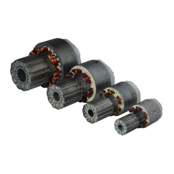
The NK frameless servomotor are the active parts of a servo motor: a rotor and a stator. The NK series can not be used alone and must integrated into a complete system to provide a complete servomotor. The design, the construction, the certification and the tests are the responsibility of the integrator. -
Page 8: Applications
2.3. Applications Medical: Blood pumps, air pump, radiology tables,… Machine tools: Ancillary axis, spindle, axis… Marine Submarine Semiconductor Hand tool: screwdriver,… Packaging machinery Robot applications Special machines Pump Compressor Fully optimized Frameless Integration mechanical Servomotors system Partner of your integration : ... - Page 9 Examples Electric cylinder Mains benefits: Cost (coupling, bearings, motor front flange are deleted and cylinder frame is simple) Compact (40% smaller than standard cylinder) Excellent control due to the high mechanical stiffness (no coupling) Lower weight (ideal for robot application) Pump Mains benefits:...
-
Page 10: Motor Description
2.4. Motor description Copper windings impregnated with resin STATOR Stator stack laminations Rotor stack laminations Rivets Rotor flange for Magnets ROTOR balancing 2.5. General Technical Data NK3, NK4,NK6 Motor type Permanent-magnet synchronous motor Magnets material Neodymium Iron Boron Number of poles Degree of IP00 protection... -
Page 11: Product Code
2.6. Product Code Code Product Series Motor size 1, 2, 3, 4, 6 or 8 in relation with the motor diameter Motor length up to 60 depend on size Windings variant E: standard serial windings class F W: serial windings class F water cooled Feedback Sensor A: resolver 2 poles transformation ratio = 0.5 K: without sensor... -
Page 12: Technical Data
At high speed, the calculation is more complex, and the derating is much more important. Please refer to PARKER to know the precise data of Torque derating according to ambient temperature at high speed for a specific motor. Illustration:... - Page 13 The following formula gives an indicative of the torque derating at low speed. But in any case refer to PARKER technical department to know the exact values At low speed the torque derating is given by the following formula for an water Inlet temperature >...
-
Page 14: Thermal Equivalent Torque (Rms Torque)
3.1.3. Thermal equivalent torque (rms torque) The selection of the right motor can be made through the calculation of the rms torque (i.e. root mean squared torque) (sometimes called equivalent torque). This calculation does not take into account the thermal time constant. It can be used only if the overload time is much shorter than the copper thermal time constant. - Page 15 Selection of the motor : The motor adapted to the duty cycle has to provide the rms torque M at the rms speed(*) without extra heating. This means that the permanent torque M available at the average speed presents a sufficient margin regarding the rms torque M rms.
-
Page 16: Drive Selection
Please refer to the drive technical documentation for any further information and to select the best motor and drive association. AC890 PARKER drive example: The rated current provided by the AC890 drive depends on its rated power and its mode selection. “Vector mode” is used for induction motors while “Servo mode” is used for brushless AC motors. - Page 17 NX620EAR ELECTRONIC DRIVE (1) DIGIVEX 7.5/15 et DIGIVEX 8/16 (230V) (400V) (480V) Torque at low speed Permanent current at low speed 5.31 Peak torque 26.7 Example n°1 : Current for the peak torque 21.2 Back emf constant at 1000 rpm (25°C)* 95.7 The application needs: Nm/A...
- Page 18 Example n°2 : This times; the application needs : - a permanent torque of 5.8 Nm at low speed, - a rms torque of 5.8 Nm at the rms speed of 1890 rpm, - an acceleration torque of 8.8 - a maximal speed of 2800 rpm. Selection of the motor: The selected motor is the type NK620EAR.
-
Page 19: Current Limitation At Stall Conditions (I.e. Speed < 3 Rpm)
3.1.5. Current limitation at stall conditions (i.e. speed < 3 rpm) Recommended reduced current at speed < 3 rpm: reduced Warning: The current must be limited to the prescribed values. If the nominal torque has to be maintained at stop or low speed (< 3 rpm), imperatively limit the current to 70% of I (permanent current at low speed), in order to avoid an excessive overheating of the motor. -
Page 20: Nk Characteristics: Torque, Speed, Current, Power
3.2. NK Characteristics: Torque, speed, current, power… The torque vs speed graph below explains different intrinsic values of the next tables. Torque Peak Torque Permanent Rated Low Speed Power Torque Rated torque Stall torque 3 rpm Rated Speed speed speed 20 - PVD 3664_GB_NK-November 2016.Docx... -
Page 21: Nk Data With Natural Cooling - Mains Voltage 230V
NK data with natural cooling – Mains voltage 3.2.1. 230V Rated Rated Rated Peak Peak Max. speed speed Power Torque Current Torque Current Speed Motor torque Current Mpeak I peak Nmax (kW) (Nm) [Arms] [Nm] [Arms] [rpm] [Nm] [Arms] 6000 NK110E_P 0,21 0,33... -
Page 22: Nk Data With Natural Cooling - Mains Voltage 400V
NK data with natural cooling – Mains voltage 3.2.2. 400V Rated Rated Rated Peak Peak Max. speed speed Power Torque Current Torque Current Speed Motor torque Current Mpeak I peak Nmax (kW) (Nm) [Arms] [Nm] [Arms] [rpm] [Nm] [Arms] NK210E_T 0,385 0,613 6000... -
Page 23: Further Data With Natural Cooling
3.2.4. Further Data with natural cooling Moment of Winding Motor Kt (sine) Inductance Inertia Motor Resistance Weight [Vrms/krpm] [Nm/Arms] [mH] [ohms] [kg] [kgmm²] NK110E_P 29,9 0,455 22,60 26,5 NK210E_T 48,6 0,749 16,30 35,0 NK210E_P 32,6 0,503 7,74 15,8 NK210E_T 48,6 0,749 16,30 35,0... -
Page 24: Further Data With Water Cooling
3.2.5. Further Data with water cooling Moment of Winding Kt (sine) Inductance Inertia Water Flow Motor Resistance [Vrms/krpm] [Nm/Arms] [mH] [l/min] [ohms] [kgmm²] NK310W_F 22,2 0,349 1,08 2,90 NK420W_D 24,0 0,375 0,49 2,14 NK430W_D 33,5 0,523 0,58 2,50 NK620W_C 33,0 0,517 0,24 1,91... -
Page 25: Efficiency Curves
3.2.6. Efficiency curves Caution: The efficiency curves are typical values. They may vary from one motor to an other Caution: The efficiency curves are given for an optimal motor control (no voltage saturation and optimal phase between current and EMF) Caution: The efficiency curves do not include the losses due to the switching frequency. - Page 26 3.2.6.1. Series NK110E Constant efficiency curves of the motor NX110EAP Efficiency [%] 68 70 1000 2000 3000 4000 5000 6000 Speed [rpm] 3.2.6.2. Series NK205E Constant efficiency curves of the motor NX205E Efficiency [%] 1000 2000 3000 4000 5000 6000 7000 Speed [rpm] 26 - PVD 3664_GB_NK-November 2016.Docx...
- Page 27 3.2.6.3. Series NK210E Constant efficiency curves of the motor NX210E Efficiency [%] 1000 2000 3000 4000 5000 6000 7000 8000 9000 10000 Speed [rpm] 3.2.6.4. Series NK310E Constant efficiency curves of the motor NX310E Efficiency [%] 72 74 1000 2000 3000 4000 5000...
- Page 28 3.2.6.5. Series NK420E Constant efficiency curves of the motor NX420E Efficiency [%] 1000 2000 3000 4000 5000 6000 7000 Speed [rpm] Constant efficiency curves of the motor 3.2.6.6. Series NK430E NX430E Efficiency [%] 64 66 1000 2000 3000 4000 5000 6000 Speed [rpm] 28 - PVD 3664_GB_NK-November 2016.Docx...
- Page 29 3.2.6.7. Series NK620E Constant efficiency curves of the motor NX620E Efficiency [%] 1000 2000 3000 4000 5000 6000 Speed [rpm] Constant efficiency curves of the motor 3.2.6.8. Series NK630E NX630E Efficiency [%] 1000 2000 3000 4000 5000 6000 Speed [rpm] 29 - PVD 3664_GB_NK-November 2016.Docx...
- Page 30 Constant efficiency curves of the motor 3.2.6.9. Series NK820E NX820E Efficiency [%] 76 78 1000 2000 3000 4000 5000 6000 Speed [rpm] 3.2.6.10. Series NK840E Constant efficiency curves of the motor NX840E Efficiency [%] 1000 1500 2000 2500 3000 3500 4000 4500 Speed [rpm]...
- Page 31 3.2.6.11. Series NK860E Constant efficiency curves of the motor NX860E Efficiency [%] 1000 1500 2000 2500 3000 Speed [rpm] 31 - PVD 3664_GB_NK-November 2016.Docx...
- Page 32 Constant efficiency curves of the motor 3.2.6.12. Series NK860V NX860V Efficiency [%] 1000 1500 2000 2500 3000 3500 Speed [rpm] 3.2.6.13. Series NK860W Constant efficiency curves of the motor NX860W Efficiency [%] 1000 1500 2000 2500 3000 3500 4000 4500 Speed [rpm] 32 - PVD 3664_GB_NK-November 2016.Docx...
-
Page 33: Electromagnetic Losses
3.2.7. Electromagnetic losses Caution: Following data result from our best estimations but are indicative. They can vary from one motor to another and with temperature. No responsibility will be accepted for direct or indirect losses or damages due to the use of these data. Tf: Rotor shaft Dynamic Friction Kd: Rotor shaft Viscous Damping Torque losses = Tf + Kd x speed/1000... -
Page 34: Time Constants Of The Motor
3.2.8. Time constants of the motor 3.2.8.1. Electric time constant: elec With following values given in the motor data sheet inductance of the motor phase to phase [H], ph_ph resistance of the motor phase to phase at 25°C [Ohm]. ph_ph Example: Motor series NK620EAR... - Page 35 Remarks: For a DC motor, the mechanical time constant represents the duration needed mech to reach 63% of the final speed when applying a voltage step without any resistant torque. However this value makes sense only if the electric time constant is much elec ...
-
Page 36: Speed Ripple
(neither external inertia nor resistant torque). 3.2.10. Cogging torque The typical cogging for a NK series below is the maximum value peak to peak in N.cm: Cooging Maxi Motor [N.cm]... -
Page 37: Rated Data According To Rated Voltage Variation
3.2.11. Rated data according to rated voltage variation The nominal characteristics and especially the rated speed, maximal speed, rated power, rated torque, depend on the nominal voltage supplying the motor considered as the rated voltage. The rated data mentioned in the data sheet are given for each association of motor and drive. - Page 38 Maximum speed: The former maximum speed N = 3900 rpm obtained with U =400 V and N =3900 rpm leads to the new maximum speed N given as follows: max2 3476 3900 3476 3900 N.B. If the rated voltage increases (U >...
-
Page 39: Voltage Withstand Characteristics Of Nk Series
3.2.12. Voltage withstand characteristics of NK series The motors fed by converters are subject to higher stresses than in case of sinusoidal power supply. The combination of fast switching inverters with cables will cause overvoltage due to the transmission line effects. The peak voltage is determined by the voltage supply, the length of the cables and the voltage rise time. -
Page 40: Dimension Drawings
3.3. Dimension drawings 3.3.1. 40 - PVD 3664_GB_NK-November 2016.Docx... -
Page 41: Nk2
3.3.2. 41 - PVD 3664_GB_NK-November 2016.Docx... -
Page 42: Nk3
3.3.3. 42 - PVD 3664_GB_NK-November 2016.Docx... -
Page 43: Nk4
3.3.4. 43 - PVD 3664_GB_NK-November 2016.Docx... -
Page 44: Nk6
3.3.5. 44 - PVD 3664_GB_NK-November 2016.Docx... -
Page 45: Nk8
3.3.6. 45 - PVD 3664_GB_NK-November 2016.Docx... -
Page 46: Nk3
3.3.1. NK3..W 46 - PVD 3664_GB_NK-November 2016.Docx... -
Page 47: Nk4
3.3.2. NK4..W 47 - PVD 3664_GB_NK-November 2016.Docx... -
Page 48: Nk6
3.3.3. NK6..W 48 - PVD 3664_GB_NK-November 2016.Docx... -
Page 49: Nk8
3.3.4. NK8..W 49 - PVD 3664_GB_NK-November 2016.Docx... -
Page 50: Motor Mounting Recommendations
3.4. Motor mounting recommendations Warning : The recommendations in this chapter are general. It is the integrator responsibility to check if it complies with his application and to chose and define the correct way to integrate the kit according to his application, all the regulations and standards applicable. -
Page 51: Servomotor Typical Construction
3.4.2. Servomotor typical construction Connector Deep groove ball bearing blocked Motor Deep groove ball frame bearing free in Sensor translation Spring ring ROTOR Shaft STATOR Cast iron ring 3.4.3. Bearings recommendation The arrangement bearings choice is a key point fot the motor design. It depend on speed, load and life time needed. -
Page 52: Mechanical Interfaces
3.4.4. Mechanical interfaces The mechanical interfaces requirements for the user structure must comply with the following drawings and values. 3.4.4.1. Rotor interfaces To fit the rotor on the shaft, apply a force (Fmaxi from the following tab) with a press near the center with a no magnetic part. - Page 53 3.4.4.2. Natural cooled stator interfaces The stator can be shrink fitted inside an aluminium housing (with a yield strength >160 Mpa), or a steel housing (with a yield strength > 350Mpa), or stainless steel housing (with a yield strength > 290Mpa). The housing has to be heated at 250°C to 300°C and the stator inserted in the housing.
- Page 54 3.4.4.3. Water cooled stator interfaces 30° Motor (mm) 82H8 100H8 131H8 163H8 54 - PVD 3664_GB_NK-November 2016.Docx...
-
Page 55: Water Cooled Version Recommendations
5 bars air pressure during 30 minutes and check if there is not pressure decreasing. Caution: Water inlet and outlet must be aligned with the cables inlet to guarantee an optimized cooling circulation. O-ring Cross Working PARKER part Motor diameter section Material Hardness temperature... -
Page 56: Design Compliance
3.4.6. Design Compliance The integrator is responsible for compliance with directives, regulations and standards. Nonexhaustively, the integrator has to certify the complete motor design in order to be comformed to the guide lines (nonexhaustively). Low Voltage Directive 2014/35/EU RoHs Directive 2011/65/CE ... -
Page 57: Ground Continuity Compliance
Minimum clearances for insulation: Minimum clearances in air in millimeters up to 2000 m above sea level Required Case A Case B impulse (inhomogeneous field) (homogeneous field) Voltage rms withstand Pollution degree Pollution degree voltage 0,06 0,06 from 100V to 250V 1500 up to 500V 2000... -
Page 58: Overspeed Test
3.4.12. Overspeed test A qualification test at 20% above the rated speed during at least 1 min, must be carried out according to the standard IEC 60034-1. 3.4.13. EMC Directive cf. guide lines 2004-108 CE and standard IEC 61800-3 It is the integrator's responsibility to ensure that the complete motor and drive in use comply with the EMC directive. -
Page 59: Cooling
Natural and fan cooled motor The ambient air temperature shall not be less than -15°C and more than 40°C. NK Series are housed in a motor frame detailled in § 3.4.4.2. Natural cooled stator interfaces Warning: To reach the motor performances calculated, the complete... -
Page 60: Water Cooled Motor
3.5.2. Water cooled motor Danger: The cooling system has to be operational when the motor is running or energized. Danger: The Inlet temperature and the water flow have to be monitored to avoid any exceeding temperature values. Caution: When motor is not running, the cooling system has to be stopped 10 minutes after motor shut down. -
Page 61: Additives For Water As Cooling Media
3.5.3. Additives for water as cooling media Please refer to motor technical data for coolant flow rates. The water inlet temperature must not exceed 25°C without torque derating. The water inlet temperature must not be below 5°C. The inner pressure of the cooling liquid must not exceed 5 bars. Caution: To avoid the appearance of corrosion of the motor cooling system, the water must have anti-corrosion additive. -
Page 62: Motor Cooling Circuit Drop Pressure
3.5.4. Motor cooling circuit drop pressure The tab below describes the drop pressure at the water flow rate from the motor data: Motor type Drop pressure All NK…W 0.5 bar Note : all motors drop pressure are checked before shipping. 3.5.5. -
Page 63: Flow Derating According To Glycol Concentration
3.5.6. Flow derating according to glycol concentration Glycol concentration [% ] 10.2 10.6 11.1 11.8 12.4 15.3 15.9 16.7 17.6 18.7 20.4 21.2 22.2 23.5 24.9 25.5 26.5 27.8 29.4 31.1 30.6 31.8 33.4 35.3 37.3 35.7 37.1 38.9 41.1 43.6 40.8 42.4... - Page 64 Main formulas Power dissipatio Flow rate With: Flow rate [l/min] Power_dissipation [W] ° Gradient inlet-outlet [°C] Cp thermal specific capacity of the water as coolant [J/kg°K] (Cp depends on the % glycol concentration please see below) Thermal specific capacity Cp according to % glycol concentration and temperature We have considered an average temperature of the coolant of 30°C.
-
Page 65: Water Cooling Diagram
3.5.7. Water cooling diagram Recommendation: The use of a filter allows to reduce the presence of impurities or chips in the water circuit in order to prevent its obstruction. We recommend 0.1mm filter. This section shows typical water cooling diagram : There is no recommendation on water inlet and... - Page 66 No Parallel Circuit Chiller or Exchanger without flow control Pump Servomotor To other(s) device(s) No Serial Circuit Pump Servomotors 66 - PVD 3664_GB_NK-November 2016.Docx...
-
Page 67: Thermal Protection
3.6. Thermal Protection Different protections against thermal overloading of the motor are proposed as an option: Thermoswitch, PTC thermistors or KTY temperature built into the stator winding. No thermal protection are available for the NK1 motor The thermal sensors, due to their thermal inertia, are unable to follow very fast winding temperature variations. -
Page 68: Temperature Measurement With Kty Sensors
3.6.2. Temperature measurement with KTY sensors: Motor temperature can also be continuously monitored by the drive using a KTY 84- 130 thermal sensor built in to the stator winding. KTY sensors are semiconductor sensors that change their resistance according to an approximately linear characteristic. -
Page 69: Power Electrical Connections
3.7. Power Electrical Connections 3.7.1. Wires sizes In every country, you must respect all the local electrical installation regulations and standards. Not limiting example in France: NFC 15-100 or IEC 60364 as well in Europe. Cable selection depends on the cable construction, so refer to the cable technical documentation to choose wire sizes Some drives have cable limitations or recommendations;... -
Page 70: Conversion Awg/Kcmil/Mm²
Example of sizes for H07 RN-F cable : Conditions of use: Case of 3 conductors type H07 RN-F: 60°C maximum Ambient temperature: 30°C Cable runs on dedicated cables ways Current limited to 80%*I at low speed or at motor stall. Example: Io=100 Arms Permanent current at standstill : 80 Arms... -
Page 71: Motor Cable Length
For motors windings which present low inductance values or low resistance values, the own cable inductance, respectively own resistance, in case of large cable length can greatly reduce the maximum speed of the motor. Please contact PARKER for further information. -
Page 72: Feedback System
3.8. Feedback system An angular position sensor is often used to run the motor and it depends on the drive functionalities. A drive with a sensorless mode needn’t a feedback system. A classic position sensor is an encoder, but a resolver could be an lower cost and more robust alternative. - Page 73 3.8.1.3. Resolver characteristics NK4, NK6 & NK6 & NK8 Motor associated NK2 & NK3 Parker part number 220005P1000 220005P1001 220005P1002 220005P1003 Electrical Values @ 8 kHz specification Polarity 2 poles Input voltage 7 Vrms 70mA 56mA Input current 86mA maximum...
- Page 74 3.8.1.4. Cables and connectors associated to the resolver To connect NK motor with a connector M23 to PARKER drive : AC890, COMPAX3 or SLVD, you can use complete cable with part number on the tabs below. The "xxx" in the part number must be replaced by the length in meter.
- Page 75 3.8.1.6. Resolver drawings Resolver part number 220005P1000 Resolver part number 220005P1001 Resolver part number 220005P1002 75 - PVD 3664_GB_NK-November 2016.Docx...
- Page 76 Resolver part number 220005P1003 76 - PVD 3664_GB_NK-November 2016.Docx...
-
Page 77: Encoder
3.8.2. Encoder Instead of a resolver we can provide an encoder: Incremental encoder incremental encoder with 10 poles commutations channels Hiperface single turn or multiturn Endat, single turn or multiturn … 77 - PVD 3664_GB_NK-November 2016.Docx... -
Page 78: Commissioning, Use And Maintenance
4. COMMISSIONING, USE AND MAINTENANCE 4.1. Instructions for commissioning, use and maintenance 4.1.1. Equipment delivery All servomotors are strictly controlled during manufacturing, before shipping. While receiving it, it is necessary to verify motor condition and if it has not been damaged in transit. -
Page 79: Machine Integration
4.2. Machine Integration 4.2.1. General warnings Caution: The integrator bears the entire responsibility for the preparation of the machine design. Danger : The integrator must certify the motor by an approved organism to comply with all the regulations (CE, UL, …) and perform all the mandatory routine tests (exemples : IEC60034…) Attention: Rotor has strong permanent magnets. - Page 80 The axial attraction force (Fa) during the rotor insertion in the stator is: Rotor Stator Rotor Stator Magnetic attraction Radial attraction (Fr) is proportional with axial offset (x): Fr(N) = Kr . x(mm) Motor Xmax N/mm NK110 NK210 1000 NK310 1600 NK420 2000...
-
Page 81: Tightening Torque
4.2.2. Tightening torque The table below gives the average tightening torques required regarding the fixing screw diameter. These values are valid for both motor’s feet and flange bolting. Screw diameter Tightening torque Screw diameter Tightening torque M2 x 0.35 0.35 N.m M9 x 1.25 31 N.m M2.5 x 0.4... -
Page 82: Rotor Integration Step By Step
4.2.3. Rotor integration step by step Step 1 Push down the rotor on the shaft with a press. Maximum press force is described in §3.4.4.1. Make sure you have followed the shaft interface instruction (see §3.4.4.1). Rotor Follow interface recommendations (chamfer at 30°) to have an easy mounting 82 - PVD 3664_GB_NK-November 2016.Docx... - Page 83 Step 2 Rotor balancing is an option and depend on speed application. For high speed application, rotor must be balanced with bearings and shaft. Balancing recommended level : G2.5 Area to add or remove material to balance rotor Rotors are not balanced before delivery. The electro-spindle manufacturer must balance the complete spindle rotor (shaft, bearings and rotor) using an appropriate method: for example, by removing or add material from shaft.
-
Page 84: Natural Cooled Stator Integration Step By Step
4.2.1. Natural cooled stator integration step by step Step 1 Increase the housing temperature to 250°C to 300°C Step 2 Push down the stator in the water jacket. Chamfer at 30° to have an Make sure you have followed the easy mounting housing interface instruction (§3.4.2.2). - Page 85 Step 3 After fitting, let stator+housing go back to ambient temperature 85 - PVD 3664_GB_NK-November 2016.Docx...
-
Page 86: Water Cooled Stator Integration Step By Step
4.2.2. Water cooled stator integration step by step Step 1 Assemble O-Ring seal on water jacket. O-Ring information’s for standard water jacket in chapter “O-Ring specification” (§3.4.5.1). Step 2 Prepare the cooling jacket for his integration Water inlet and outlet must be aligned with the cables inlet Make sure you have... -
Page 87: Motor Integration
4.2.3. Motor integration Rotor assembly into stator There are different solutions, depends of the weight of the rotor: solution: for light motor Step 1 Screw the stator onto the front flange. Put the stator onto workbench. Put spring ring. Prepare rotor : fit onto rear flange. - Page 88 Step 3 Danger : do not put your hand inside the motor during way- down. Make sure you have done chamfers at 30°. 88 - PVD 3664_GB_NK-November 2016.Docx...
- Page 89 Step 4 Screw the rear flange on the stator to close motor. Step 5 Last step is the encoder or resolver mounting Caution: After 15 days, check all tightening torques on screws and nuts 89 - PVD 3664_GB_NK-November 2016.Docx...
- Page 90 solution : for heavy motor Step 2 For an easier assembly, use extra smooth and thread bars outside of the stator to guide and push rotor onto the stator. Step 4 Caution : do not put your hand inside the motor during way- down.
- Page 91 Step 5 Make sure the rotor is well setting up in place. Step 6 Unscrew the mobile flange onto the rear flange. Fit rear flange. 91 - PVD 3664_GB_NK-November 2016.Docx...
- Page 92 Step 7 Last step is the encoder or resolver mounting Caution: After 15 days, check all tightening torques on screws and nuts 92 - PVD 3664_GB_NK-November 2016.Docx...
-
Page 93: Resolver Mounting
4.3. Resolver mounting Caution: The resolver is a high precision, carefully manufactured device and the following precautions should be taken to maintain its characteristics: ⇒ avoid shocks ⇒ avoid impact between rotor and stator. ⇒ do not hold the stator by its cables ⇒... -
Page 94: Setting Of The Resolver
4.3.2. Setting of the resolver At the time of the procedure of setting, it is imperative to observe the 3 following conditions: • The motor rotor must be free in rotation. The torque of maximum friction on the rotor should not exceed 1 % of torque permanent motor. •... -
Page 95: Electrical Connections
4.4. Electrical connections Danger: Do not connect the kit to any electric supply . Only the motor can be connected to an electric supply. Danger: Check that the power to the electrical cabinet is off prior to making any connections. Caution: The wiring must comply with the drive commissioning manual and with recommended cables. - Page 96 Please, read §3.7 "Electrical connection" to have information about cable. Many usefull informations are already available in the drive documentations. The motor must be connected to the servo amplifier according to the drive user manual. The color code given in the table must be followed : Signal Color Black...
-
Page 97: Encoder Cable Handling
4.5. Encoder cable handling Danger: before any intervention the drive must be stopped in accordance with the procedure. Caution: It is forbidden to disconnect the Encoder cable under voltage (high risk of damage and sensor destruction). Attention: Do not mix feedback wires with motor wires to avoid EMI (electromagnetic interference). -
Page 98: Tests
4.6. Tests The motor components delivered by Parker are tested : • dielectric test, • surge test, • winding resistance and inductance, • direction of rotation, • rotor flux. But complete motor must be tested for safety reason and to comply with the regulations (CE,…). -
Page 99: Troubleshooting
Whenever an operating incident occurs, consult the relevant servo drive installation instructions (the troubleshooting display indications will help you in your investigation) or contact us at: http://www.parker.com/eme/repairservice. Check there is no mechanical blockage or if the motor You note that the motor does not turn by hand terminals are not short-circuited. - Page 100 You find that the motor Several possible explanations : Unsatisfactory mechanical balancing is too noisy There is friction from the brake: mechanical jamming. Defective coupling Loosening of several pieces Poor adjustment of servo drive or position loop : check rotation in open loop The motor is warmer on Air bubbles can be stocked in the water cooling circuit.
Need help?
Do you have a question about the NK Series and is the answer not in the manual?
Questions and answers