Parker PSD1-S Manual
Servo drive
Hide thumbs
Also See for PSD1-S:
- Quick manual (31 pages) ,
- Installation instructions manual (109 pages) ,
- Quick manual (26 pages)

Related Manuals for Parker PSD1-S


Summary of Contents for Parker PSD1-S
- Page 1 192-011004N5 PSD1-S Short Description 2017-08 PSD1-S: Parker Servo Drive 192-011004N5 DOC-0002-01-R014 Manual 2017-08 Up from release R01-03 192-011004N5 DOC-0002-01-R014 14.08.17 09:41 (20)
- Page 2 Fax: + 49 (0781) 509-98176 Internet: www.parker.com/eme http://www.parker.com/eme E-mail: EM-Motion@parker.com mailto:EM-Motion@parker.com Parker Hannifin GmbH - registered office: Bielefeld HRB 35489 Management Board: Ellen Raahede Secher, Dr.-Ing. Hans-Jürgen Haas, Günter Schrank, Kees Veraart - Chairman of the board: Hansgeorg Greuner Italy: Parker Hannifin Manufacturing Srl Electromechanical &...
-
Page 3: Table Of Contents
Warranty conditions ....................... 8 3. Conditions of utilization .................... 9 Conditions of utilization for CE-conform operation ............9 Conditions of utilization for UL certification of PSD1-S ..........11 EC declaration of conformity PSD1-S ................14 4. Connector overview PSD1-S ..................15 Front view (PSD1-S) ..................... -
Page 4: Introduction
In this chapter you can read about: • Device assignment ......................4 • Scope of delivery......................4 • Type identification plate PSD1-S ..................4 • Designated use ......................4 • Packaging, transport, storage ..................5 • Safety instructions ......................6 •... -
Page 5: Packaging, Transport, Storage
192-011004N5 PSD1-S Short Description 2017-08 Packaging, transport, storage Packaging material and transport Caution! The packaging material is inflammable, if it is disposed of improperly by burning, lethal fumes may develop. The packaging material must be kept and reused in the case of a return shipment. -
Page 6: Safety Instructions
Introduction Safety instructions In this chapter you can read about: • Explanation of the safety instructions ................6 • Working safely / qualification ..................6 • General hazards ......................6 • Special dangers ......................7 • Cautionary Markings ...................... 7 •... - Page 7 192-011004N5 PSD1-S Short Description 2017-08 2.6.4. Special dangers Danger! Due to movable machine parts and high voltages, the device can pose a lethal danger. Danger of electric shock in the case of non-respect of the following instructions. The device corresponds to DIN EN 61800-3, i.e. it is subject to limited sale.
-
Page 8: Before Commissioning The Drive, Please Observe The Following
Introduction • If the axis controller is replaced, it is absolutely necessary to transfer the configuration determining the correct operation of the drive to the device, before the device is put into operation. Depending on the operation mode, a machine zero run will be necessary. -
Page 9: Conditions Of Utilization
In this chapter you can read about: • Conditions of utilization for CE-conform operation ............9 • Conditions of utilization for UL certification of PSD1-S..........11 • EC declaration of conformity PSD1-S ................14 Conditions of utilization for CE-conform operation... - Page 10 • Earth empty wires in the cable. <100 m per axis (the cable must not be rolled up!). PSD1-S For motor cables >50 m a motor output choke is required for PSD1-S devices: • ECM-0005-01 (max. 7 A motor nominal current) Shielding connection of The cable must be fully-screened and connected to the device housing.
-
Page 11: Conditions Of Utilization For Ul Certification Of Psd1-S
• Use 60/75°C wires only Use Copper Conductors Only Do only use the Parker cables available under Accessories or assemble the cables according to the specified regulations. • Control voltage supply (24 VDC) only permissible with "class 2" power supply. - Page 12 Conditions of utilization • Integral solid state short circuit protection does not provide branch circuit protection. Branch circuit protection must be provided in accordance with the Manufacturer Instructions, National Electrical Code and any additional local codes • Suitable for use on a circuit capable of delivering not more than 5000 rms Symmetrical Amperes, 240 Vac maximum.
- Page 13 192-011004N5 PSD1-S Short Description 2017-08 3.2.4. Auxiliary connection – electrical ratings DC Bus Input / Output – X63 400 VDC / D.C. / 7 A Auxiliary Input Supply – X17 Control Supply - Max 24 VDC ±10% / max 0.5 ADC Signal I/O’s Ports (PELV circuit)
-
Page 14: Ec Declaration Of Conformity Psd1-S
Conditions of utilization EC declaration of conformity PSD1-S 14 (20) 192-011004N5 DOC-0002-01-R014 14.08.17 09:41... -
Page 15: Connector Overview Psd1-S
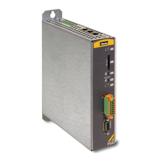
4. Connector overview PSD1-S In this chapter you can read about: • Front view (PSD1-S) ....................15 • View from below (PSD1-S) ................... 16 • View from above (PSD1-S) ..................16 Front view (PSD1-S) View from above (see on page 16) -
Page 16: View From Below (Psd1-S)
Connector overview PSD1-S View from below (PSD1-S) View from above (see on page 16) Connection of Motor To motor • HIPERFACE DSL® Motor feedback • Motor holding brake 24 VDC supply Central ground Connect ground via ring cable lug with a 10 mm... -
Page 17: Mounting And Dimensions
192-011004N5 PSD1-S Short Description 2017-08 5. Mounting and dimensions Ventilation: • During operation, the device radiates heat (heat dissipation). Please provide for a sufficient mounting distance below and above the device in order to ensure free circulation of the cooling air. -
Page 18: Technical Data
Current on the mains PE Supply networks Possible supply networks Circuit breakers for operation according to CE. Circuit breakers for UL und CSA see UL Chapter (see on page 11). Control Voltage 24 VDC PSD1-S Category Specifications Voltage operating range 21 - 27 VDC Ripple 0.5 Vss... -
Page 19: Index
Size / Weight • 18 Control requirements • 11 Special dangers • 7 Control Voltage 24 VDC PSD1-S • 18 Technical Data • 18 Data of integrated dynamic brake unit • 13 Tightening torque of the wiring terminals • 12 Designated use •... - Page 20 Index 20 (20) 192-011004N5 DOC-0002-01-R014 14.08.17 09:41...
Need help?
Do you have a question about the PSD1-S and is the answer not in the manual?
Questions and answers