Sign In
Upload
Manuals
Brands
Leuze Manuals
Accessories
LRS
Leuze LRS Manuals
Manuals and User Guides for Leuze LRS. We have
1
Leuze LRS manual available for free PDF download: Technical Description
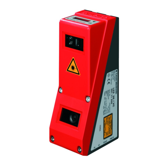
Leuze LRS Technical Description (125 pages)
Light Section Sensors, Line Range Sensor
Brand:
Leuze
| Category:
Accessories
| Size: 5 MB
Table of Contents
Table of Contents
3
Figures and Tables
9
1 General Information
11
Explanation of Symbols
11
Declaration of Conformity
11
2 Safety Notices
12
General Safety Notices
12
Documentation
12
Safety Regulations
12
Repair
12
Safety Standards
12
Approved Purpose
12
Areas of Application
12
Working Safely
13
Figure 2.1: Name Plate and Warning Notices
14
3 Operating Principle
16
Generation of 2D Profiles
16
Figure 3.1: Light Section Sensor Design
16
Limits of Light Section Sensors
17
Occlusion
17
Figure 3.2: Occlusion
17
Possible Measure against Laser Occlusion
18
Possible Measures against Receiver Occlusion
18
Minimum Object Size
19
Figure 3.3: Typical Minimum Object Size LRS 36
19
4 Device Description
20
Overview of Light Section Sensors
20
Mechanical Design
20
General Performance Characteristics
20
Figure 4.1: Mechanical Design of Leuze Light Section Sensors
20
Line Range Sensor - LRS
21
Specific Performance Characteristics
21
Typical Areas of Application
21
Operating the Sensor
22
Connection to PC / Process Control
22
Configuration
22
Detection Operation
22
Activation - Laser On/Off
22
Figure 4.2: Activation Input Signal Sequence
22
Triggering - Free Running
23
Figure 4.3: Trigger Input Signal Sequence
23
PROFIBUS Trigger
24
Cascading
24
Trigger Settings
24
Cascading Settings
24
Figure 4.4: Signal Sequence for Cascading
24
Figure 4.5: Cascading Application Example
24
Detection Functions LRS
25
Inspection Task
25
Analysis Window (AW)
25
Analysis Results
26
Definition of Aws and Analysis Results
27
Figure 4.6: Principle of Object Detection - Areas with Laser Occlusion Are Shown in Orange
27
Application Examples
28
Zero Check of Cases
28
Figure 4.7: Zero Check of Cases
28
Single or Multiple Track Presence/Absence Detection on Transport Systems
29
Creation of Inspection Tasks
29
Figure 4.8: Single or Multiple Track Presence/Absence Detection on Transport Systems
29
5 Installation and Mounting
30
Storage, Transportation
30
Unpacking
30
Figure 5.1: Device Name Plate LRS
30
Mounting the LRS
31
Figure 5.2: Fastening Options
31
Figure 5.3: Mounting Example LRS
31
BT 56 Mounting Device
32
Figure 5.4: BT 56 Mounting Device
32
BT 59 Mounting Device
33
Figure 5.5: BT 59 Mounting Device
33
Device Arrangement
34
Selecting a Mounting Location
34
Aligning the Sensor
34
Attach Laser Warning Sign
35
Cleaning
35
Figure 5.6: Alignment to the Measuring Plane
35
6 Electrical Connection
36
Figure 6.1: Location of the Electrical Connections
36
Figure 6.2: Connections of the LRS
36
Safety Notices
37
Shielding and Line Lengths
38
Shielding
38
General Shielding Information
39
Connect the Ground Potential to the Light Section Sensors
40
Connecting the Cable Shield in the Switch Cabinet
40
Figure 6.3: Connecting the Ground Potential to the Light Section Sensor
40
Figure 6.4: Connecting the Cable Shield in the Switch Cabinet
40
Connecting the Cable Shield to the PLC
41
Figure 6.5: Connecting the Cable Shield to the PLC
41
Connecting
42
Connection X1 - Logic and Power
42
Power Supply
42
Activation Input Inact
42
Trigger Input Intrig
42
Figure 6.6: Internal Wiring at X1
42
Cascading Output Outcas
43
Output "Ready" Outready
43
Connection X2 - Ethernet
43
Ethernet Cable Assignment
43
Figure 6.7: HOST / BUS in Cable Assignments on RJ-45
43
Connection X3 - Switching Inputs/Outputs (Only LRS 36/6)
44
Switching Outputs of Connection X3
44
Switching Inputs of Connection X3
44
Connection X4 - PROFIBUS DP (Only LRS 36/PB)
45
7 Display and Control Panel
46
Indicator and Operating Elements of the
46
LED Status Displays
46
Control Buttons
46
Figure 7.1: Indicator and Operating Elements of the LRS
46
Displays
47
Alignment Aid
47
Status Display
47
Command Mode
47
Menu Description
49
Structure
49
Operation/Navigation
52
Menu Navigation
52
Selecting Values or Selection Parameters for Editing
52
Editing Value Parameters
52
Editing Selection Parameters
52
Reset to Factory Settings
53
Interrupting a Reset
53
Executing a Reset
53
8 Commissioning and Configuration
54
Switching on
54
Establish Connection to PC
54
Setting an Alternative IP Address on the PC
55
Commissioning
56
9 Lrssoft Configuration Software
57
System Requirements
57
Installation
57
Possible Error Message
63
Starting Lrssoft/Communication Tab
64
Figure 9.1: Initial Screen Lrssoft
64
Figure 9.2: PROFIBUS Settings
65
PROFIBUS Settings (Only LRS 36/PB)
65
Parameter Settings/Parameters Tab
67
Task Parameters Panel
67
Inspection Task Selection
67
Figure 9.3: Parameter Settings in Lrssoft
67
Operation Mode
68
Activation
68
Trigger Output Mode
68
Light Exposure
68
Field of View
69
Apply Settings
69
Analysis Functions Area
70
Edit Logical Combinations
70
Figure 9.4: Window "Analysis Window Definitions
70
Figure 9.5: Definition of Analysis Windows (AW)
70
Edit Logical Combinations
72
Figure 9.6: "Analysis Window Combination Tables" Window
72
Figure 9.7: Definition of Logic Combinations of Several Aws
73
Single Shot Mode Area
74
Global Parameters Area
74
Detection Function/Visualization Tab
75
Evaluating Saved Detection Data
75
Figure 9.8: Lrssoft Visualization
75
Menu Commands
76
Saving Parameter Settings/File Menu
76
Transmitting Parameter Settings/Configuration Menu
76
Managing Detection Data/Measure Records Menu
77
Zoom and Pan/Toolbar
77
Figure 9.9: Zoom Function
77
Definition of Inspection Tasks
78
Typical Procedure
78
10 Integrating the LRS in the Process Control (Ethernet)
79
General Information
79
Protocol Structure: Ethernet
79
Protocol Structure
80
Header
80
10.2.1 Command Number
80
10.2.2 Packet Number
80
10.2.3 Transaction Number
80
10.2.4 Status
81
10.2.5 Encoder High / Low
81
10.2.6 Scan Number
82
10.2.7 Type
82
10.2.8 Number of User Data
82
10.2.9 Evaluation Telegram
82
Ethernet Commands
83
10.3.1 Elementary Commands
84
10.3.2 Commands in Command Mode
85
User Data in Command Mode (Command Parameters)
86
Set Laser Gate
86
Set Actual Inspection Task
86
Get Actual Inspection Task
86
Set Scan Number
87
Set Single Inspection Task Parameter (Beginning with Firmware V01.40!)
87
Get Single Inspection Task Parameter (Beginning with Firmware V01.40!)
89
10.3.4 Commands in Detection Mode
91
Working with the Protocol (Ethernet)
91
Command Without User Data
91
Command with User Data
92
Operation with Lxs_Lib.dll
93
Access
93
Additional Support When Integrating Sensors
93
11 Integration of the LRS 36/PB in the PROFIBUS
94
General Information
94
Characteristics of LRS 36/PB
94
PROFIBUS Address Assignment
95
Automatic Address Assignment
95
Address Assignment with Lrssoft
95
Address Assignment with Key Pad and Display
95
General Information about the GSD File
96
Overview of the GSD Files
97
Output Data (from Viewing Position of Control)
97
Input Data (from Viewing Position of Control)
98
Output Data Description
99
PROFIBUS Trigger
99
Activation - Sensor Activation
99
Inspection Tasks - Selection of Inspection Tasks
99
Input Data Description
100
11.6.1 Module M1
100
Scan Number
100
Sensor Info
100
Sensor State
101
11.6.2 Module M2
101
Evaluation Results of the Analysis Window
101
11.6.3 Module M3
102
Number of Hit Points (Current Hits) in Analysis Window 1
102
Number of Hit Points (Current Hits) in Analysis Window 2
102
Number of Hit Points (Current Hits) in Analysis Window 5
102
11.6.4 Module M4
102
Number of Hit Points (Current Hits) in Analysis Window 6
103
Number of Hit Points (Current Hits) in Analysis Window 9
103
Module M5
103
Number of Hit Points (Current Hits) in Analysis Window 10
103
Number of Hit Points (Current Hits) in Analysis Window 16
103
12 Diagnostics and Troubleshooting
104
General Causes of Errors
104
Interface Error
105
Error Messages in Display (Starting from Firmware V01.40)
106
13 Maintenance
108
General Maintenance Information
108
Cleaning
108
Repairs, Servicing
108
Disassembling, Packing, Disposing
108
Repacking
108
14 Specifications
109
General Specifications
109
Typical Detection Range
111
Dimensioned Drawing
112
15 Type Overview and Accessories
113
Type Overview
113
15.1.1 Lps
113
15.1.2 Lrs
113
15.1.3 Les
113
Accessories
114
15.2.1 Fastening
114
Mounting Devices
114
15.2.2 Accessory Ready-Made Cables for Voltage Supply X1
114
Contact Assignment for Connection Cable X1
114
Order Codes of the Cables for Voltage Supply
115
15.2.3 Accessories for Ethernet Interface X2
115
Ready-Made Cables with M12 Plug/Open Cable End
115
Ready-Made Cables with M12 Plug/Rj-45 Plug
116
Ready-Made Cables with M12 Plug/M12 Plug
116
Connectors
117
Accessories Ready-Made Cables for X3 (Only LRS 36/6)
117
Contact Assignment for X3 Connection Cables
117
Order Code of X3 Connection Cables
117
Connection Accessories / Ready-Made Cables for X4 (Only LRS 36/PB)
118
Contact Assignment for X4 Connection Cables
118
Order Codes for X4 Connection Accessories
118
Order Code of PROFIBUS Connection Cables for X4
119
15.2.6 Configuration Software
119
16 Appendix
120
Glossary
120
Revision History / Feature List
122
16.2.1 Firmware
122
16.2.2 Configuration Software
123
Index
124
Advertisement
Advertisement
Related Products
Leuze LES 36 Series
Leuze LES 36HI Series
Leuze LBK S-01
Leuze LBK SBV
Leuze L10 Series
Leuze L10-P2C1-M20-SB20
Leuze LBK ISC
Leuze LBK SBV205
Leuze LBK ISC BUS PS
Leuze LBK ISC-02
Leuze Categories
Barcode Reader
Accessories
Measuring Instruments
Security Sensors
Safety Equipment
More Leuze Manuals
Login
Sign In
OR
Sign in with Facebook
Sign in with Google
Upload manual
Upload from disk
Upload from URL