ELECRAFT K3 Modification
Dds gain modification
Hide thumbs
Also See for K3:
- Assembly manual (84 pages) ,
- Owner's manual (82 pages) ,
- Installation and operation manual (55 pages)
Advertisement
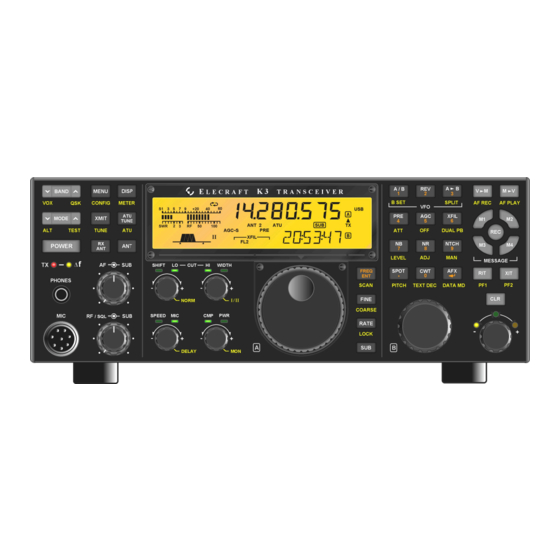
Elecraft K3
KSYN3 DDS Gain Modification
Revision A1, May 27, 2010
Copyright © 2010, Elecraft, Inc., All Rights Reserved
The KSYN3 synthesizer uses a direct digital synthesizer (DDS) circuit. In rare cases, at certain frequencies the
DDS driving signal to the Phase Locked Loop (PLL) may be marginal, resulting in a sudden shift in frequency
(commonly called "chirp"). This modification adds a resistor to the KSYN3 board that increases the DDS drive
level prevent this condition. This is an optional modification and is not required unless you are experiencing this
condition.
If you chose to make this modification and your K3 is equipped with the KRX3 subreceiver it will have two
KSYN3 synthesizers. Although only the main synthesizer is used for transmitting, both boards should be
modified to in case they are reversed at some future date.
This modification involves adding a single leaded resistor to the pc board. No SMD work is required. If needed,
the resistor may be ordered from Elecraft. See Parts Required below.
Tools Needed
A temperature controlled ESD-safe soldering iron with a fine tip and fine rosin core solder, diagonal cutters and
Phillips screwdrivers for opening the case and a DMM for making resistance measurements. An ESD wrist strap
is strongly recommended.
Does My K3 Have This Modification?
If the modification was made using a leaded resistor as described in this document, the resistor will be visible on
the side of the KSYN3 board closest to the front panel shield. You need to loosen the KSYN3 board mounting
screws and tilt the board away from the front panel shield slightly to see the resistor. If the resistor is not
present, you may have a board that was modified at the factory by replacing a SMD resistor. In that case,
measure the actual resistance as described under Installing the New Resistor on page 3.
Parts Required
Photo
Description
Quantity
Part
Number
Resistor,51 ohms, 1/8 watt, (grn-brn-blk)
1
E500415
Elecraft
•
www.elecraft.com
•
831-662-8345
Advertisement
Table of Contents

Subscribe to Our Youtube Channel
Related Manuals for ELECRAFT K3


Summary of Contents for ELECRAFT K3
- Page 1 This is an optional modification and is not required unless you are experiencing this condition. If you chose to make this modification and your K3 is equipped with the KRX3 subreceiver it will have two KSYN3 synthesizers. Although only the main synthesizer is used for transmitting, both boards should be modified to in case they are reversed at some future date.
- Page 2 KSYN3 board. Each board plugs into the RF board on bottom of the K3 and is held in place with two screws at the top. Loosen the screws and tip the boards to remove the split lock washers.
- Page 3 R20. Figure 3. New Resistor Installed on KSYN3 Board. K3 KSYN3 Gain Modification Page 3 of 5...
- Page 4 This washer is required to ensure proper spacing between the KSYN3 board and the shield. If your K3 did not have washers installed here, washers are included with his mod kit. Do not use inside tooth lock washers behind the board. They are large enough to short out to nearby traces and solder pads on the KSYN3 board.
- Page 5 Hold the top cover above the K3, route the speaker wire under the stiffener bar and plug it into P25 on the KIO3 board at the left rear of the K3 as shown in Figure 6. If the K144XV module is installed, the cable connector will fit under the stiffener bar at the dimple in the top of the K144XV module.
Need help?
Do you have a question about the K3 and is the answer not in the manual?
Questions and answers