Table of Contents
Advertisement
Advertisement
Table of Contents

Subscribe to Our Youtube Channel
Related Manuals for Eliwell 210 L Series


Summary of Contents for Eliwell 210 L Series
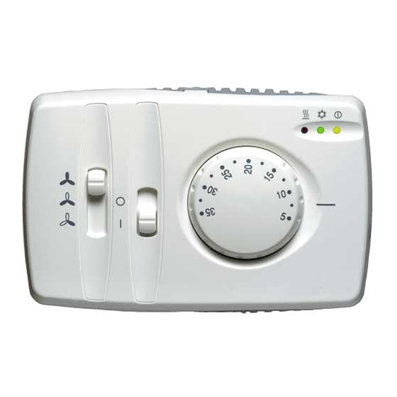
- Page 1 FC BASIC Electronic Fan-Coil Controller <IMG INFO> 340,05...
-
Page 2: Table Of Contents
CONTENTS How to use this manual............................3 Introduction ................................4 Example of a Fan-coil installation..............................4 Available models ....................................5 Installation ................................7 Warnings......................................7 Mounting......................................7 Connection diagrams ..................................8 OUT1..................................................8 OUT2..................................................8 Analogue inputs....................................8 Digital outputs ....................................9 Dip switch...................................... -
Page 3: How To Use This Manual
HOW TO USE THIS MANUAL In order to refer to the manual quickly and easily, customers may find the following useful: Callout column: Call-outs Callouts on the topics described are placed to the left of the text to allow the user to find the required information quickly. -
Page 4: Introduction
INTRODUCTION FC BASIC is an electronic controller for 2-4 pipe fan-coils. It controls the fan and the valves that regulate water flow and can also control a battery of electric heaters for winter operation. A compact wall-mounted version is available which is easy to install and to wire. FC Basic Interface F1 Interface F1... -
Page 5: Available Models
4 pipe fan-coil 4 pipe installation Water battery Hot water supply Hot water return Cold water supply Water battery Cold water return Motorised valve DELIVERY FAN: The fan is located just before the finned battery; and it takes back the room air via the inlet air duct. Fan control The air flows across the batteries before being released into the room. - Page 6 Remote air sensor and water sensor Remote air sensor and water sensor: Temperature sensor NTC, plastic cap 7x25, reinforced insulation PVC cable length=1,5m Temperature sensor NTC, metal cap 6x40, reinforced insulationPVC cable length=1,5m Product models selection guide: 2 pipe fan coil model ●...
-
Page 7: Installation
For detailed information on the functions available, please contact an authorized dealer or the Sales Office of Eliwell. Before installation, always read the labels fitted on the device. Parts which are under hazardous voltage must not be accessible under regular operating conditions. -
Page 8: Connection Diagrams
Is not directly affected by a heating or cooling source Is not mounted on an outer wall Is mounted on the wall at approx. 1,5 m from the floor Mounting Connection diagrams Connections Utilities must be connected up to the FC Basic as shown below: PLEASE NOTE: terminals 21-22 available on /N models. -
Page 9: Digital Outputs
Index Description (dial Potentiometer input: -105° +105° knob) Used to set the controller’s operating set point, between from average a minimum of 5 C° up to a maximum of 35 C°. point Related topics: Set point dial knob Range limitation Note: The presence of the water sensor is automatically detected by the controller during power start-up. -
Page 10: Dip Switch - Universal Models
<IMG INFO> 141,7 113,6 127,3 106,7 3.6.1 Dip switch – universal models * In models with INTEGRATED, AUTOMATICALLY ADJUSTING electric heaters, the HOT function is not available. **The Dip-Switch default setting (factory pre-set) is the following: DIP nr. Description default (factory pre-set)** Air sensor used Local Remote... -
Page 11: User Interface
USER INTERFACE FC Basic has three main controls plus one optional control: Dial knob • 2 sliders • • economy slider (optional) Set point dial knob Potentiometer for setting operating set point. Operating set point is altered on the basis of the angle set, from 5 to 35 Celsius. Excursion from the potentiometer centre point is an angle of +/- 105°. -
Page 12: Fan Control Slider
Fan control slider Switches the phase sectioned by the fan relay on three motor windings to achieve three different fan speeds: High/Medium/Low. Low speed: Medium speed: High speed: Operating mode slider Depending on the model (refer to table of models), it is possible to select Heating/off/Cooling operating mode or on/off (0 / I) operating mode. -
Page 13: Temperature Control Functions
TEMPERATURE CONTROL FUNCTIONS Depending on the model and available selections, FC Basic may be operated in the following modes: • COOL (summer operation) Operating modes • HEAT (winter operation) • AUTO (automatic summer – winter selection) Cooling: this is “summer” operating mode; the machine is configured for cooling. Cool Heating: this is “winter”... - Page 14 COOL mode (consent to valve and fans at water temperatures lower than 15°C), the switch to HEAT • is explained below (with relative changes to consent): 30 C 15 C water temperature C COOL MODE HEAT VALVE ON VALVE MODE VALVE OF F FAN ON FAN MODE...
-
Page 15: Regulation Algorithm
When the function mode is selected automatically depending on the difference between ambient temperature and the set Automatic DEAD point temperature, this is referrred to as an automatic DEAD ZONE change-over with lateral band. ZONE change-over Switching between heat cool settings takes place automatically as illustrated below. -
Page 16: Regulation Algorithm In Heating/Cooling Mode
Observe the explanatory diagrams below: Regulation algorithm in Heating/Cooling mode Regulation set-point algorithm in cooling mode cool./raff. room temp. temp.ambiente ˚C hysteresis/isteresi IMG INFO 5.2.1 REGULATION ALGORITHM IN COOL MODE <IMG INFO> FC BASIC User Manual 16/24... -
Page 17: Regulation Algorithm In Heat Mode
Regulation algorithm in heating mode set-point heat./risc. room temp. temp.ambiente ˚C hysteresis/isteresi 5.2.2 REGULATION ALGORITHM IN HEAT MODE FC BASIC User Manual 17/24... -
Page 18: Regulation Algorithm In Heat Mode With Supplementary Electric Heaters As Integrated Source
Regulation 5.2.3 REGULATION ALGORITHM IN HEAT MODE WITH SUPPLEMENTARY ELECTRIC HEATERS as integrated algorithm with source supplementary electric heaters set-point band/banda integrated electric heaters resis tenze elettriche in integrazione room temp. valvola/valve temp.ambiente ˚C hysteresis/is teresi hysteresis/is teresi <IMG INFO> 339,7 150,35 5.2.4... - Page 19 EXAMPLE A The water temperature is too low to guarantee any transfer of heat from the water: the electric heaters alone are used (as if in regulation mode): EXAMPLE B Intermediate situation, valve electric heaters are activated together with the temperature controller in heating mode (winter).
-
Page 20: Functions
FUNCTIONS Fan demand operation The fan will only be operated in the manually selected speed, if the regulator has detected a request for Heating or Cooling. During dead zone the fan will be OFF. Through a switch: dip switch 5 – universal models •... -
Page 21: Post-Ventilation
Post-Ventilation The fan continues to run for 1 minute* after a heating source (heating valve or electric heater) is turned off. This function prevents overheating inside the fan coil unit. *NB: Post-ventilation always lasts 1 minute (it has the priority on all other functions). For example, when a change of mode occurs (from Heat to Cool), the fan does not stop but continues to work for the determined minute. -
Page 22: Technical Features
TECHNICAL FEATURES Technical data Wall mounted version Typical Maximum Minimum Power supply voltage 230V~ 253V~ 207V~ Power supply frequency 50/60 Hz 52/63 Hz 47/57 Hz Maximum absorbed power Insulation class Protection grade IP30 IP30 IP30 Operating temperature 25C° 60C° 0C° Operating humidity (non-condensing) Storage temperature 55C°... -
Page 23: Use Of The Device
This document is exclusive property of Eliwell Controls srl. and cannot be reproduced and circulated unless expressly authorized by Eliwell Controls srl Although all possible measures have been taken by Eliwell Controls srl l. to guarantee the accuracy of this document, it does not accept any responsibility arising out of its use. -
Page 24: Analitic Index
ANALITIC INDEX 2 pipe installation .............4 LED’s ..................12 4 pipe installation .............5 Manual change over............13 Mounting................7 Analogue inputs ..............8 Anti valve sticking............21 Operating mode slider...........12 Anti-frost................20 Operating modes............13 Auto................... 13 Operating modes table ..........13 Automatic change over .......... - Page 25 FC BASIC User Manual 2006/9/ Cod: 8MA10103 FC BASIC User Manual 25/24...
Need help?
Do you have a question about the 210 L Series and is the answer not in the manual?
Questions and answers
Можно ли его заблокировать
Yes, the Eliwell 210 L Series can be locked. This is done by mounting two pegs under the dial knob next to each other, which locks the operating set point at a specific value.
This answer is automatically generated