
Subscribe to Our Youtube Channel
Related Manuals for Clarke DHC-2


Summary of Contents for Clarke DHC-2
- Page 1 DOUBLE HEADED METAL NIBBLER MODEL NO: DHC-2 PART NO: 6500233 OPERATION & MAINTENANCE INSTRUCTIONS LS0609...
-
Page 2: Cutting Capacity
INTRODUCTION Thank you for purchasing this CLARKE Double Headed Metal Nibbler. Before attempting to use this product, please read this manual thoroughly and follow the instructions carefully. In doing so you will ensure the safety of yourself and that of others around you, and you can look forward to your purchase giving you long and satisfactory service. -
Page 3: Safety Warnings
SAFETY WARNINGS The term ‘Power tool’ in the Use safety equipment. Always safety warnings refers to any wear eye protection. Safety equipment such as dust mask, electric / battery or pneumatic drill, required to use this nibbler. non-skid safety shoes, hard hat, or hearing protection used for WORK AREA SAFETY appropriate conditions will... -
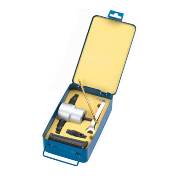
Page 4: Parts Identification
PARTS IDENTIFICATION Description Double ended cutter Cutter guide (2 Fitted + 1 Spare) Wrench Plastic Handle Double Headed Metal Nibbler... -
Page 5: Before Use
BEFORE USE FITTING THE HANDLE TO THE METAL NIBBLER Screw the handle over one Fig. 1 of the cutter guides as shown FITTING THE METAL NIBBLER TO THE DRILL Slide the nibbler drive Fig. 2 spindle into the drill. • The drill should have a speed rating of 1500- 3000 rpm. -
Page 6: Operation
OPERATION • Apply the metal nibbler to the workpiece only when running at full speed. • Always hold the metal nibbler vertical to the surface of the steel sheet and without tilting. The cut takes place during the Fig. 4 upward motion of the metal nibbler. -
Page 7: Changing The Cutter
CHANGING THE CUTTER Loosen the cutter guide fixing screws using the hex key. Lift out the coil spring and cover shown in the picture and loosen the fixing screw and nut. Slide out the cutter. Fig. 6 Replace with a new cutter and retighten the fixing screw and nut using the hex key supplied.
Need help?
Do you have a question about the DHC-2 and is the answer not in the manual?
Questions and answers