Table of Contents
Advertisement
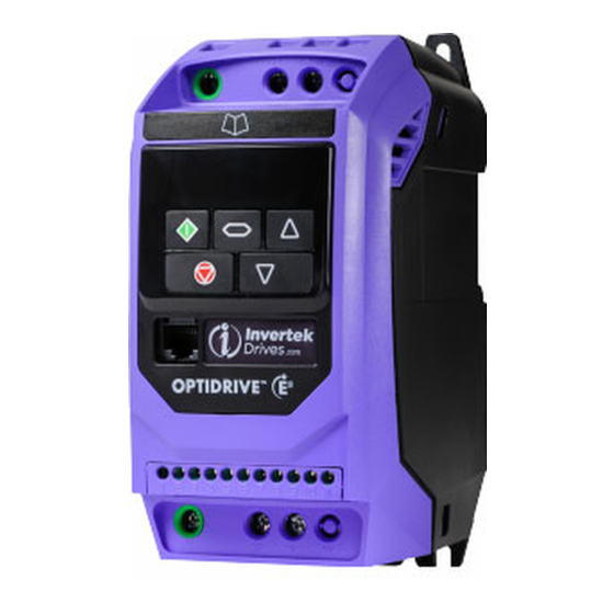
AC Variable Speed Drive
IP20 & IP66 (NEMA 4X)
0.37kW – 22kW / 0.5HP – 30HP
1 10 – 480V 3 Phase Input
0
Quick Start Up
General Information
and Ratings
Mechanical Installation
Power & Control Wiring
Operation
Parameters
Analog and Digital Input
Macro Configurations
Modbus RTU
Communications
Technical Data
Troubleshooting
1
1
2
2
3
3
4
4
5
5
6
6
7
7
8
8
9
9
10
10
Advertisement
Table of Contents

Subscribe to Our Youtube Channel
Related Manuals for Invertek Optidrive E3


Summary of Contents for Invertek Optidrive E3
- Page 1 AC Variable Speed Drive IP20 & IP66 (NEMA 4X) 0.37kW – 22kW / 0.5HP – 30HP 1 10 – 480V 3 Phase Input Quick Start Up General Information and Ratings Mechanical Installation Power & Control Wiring Operation Parameters Analog and Digital Input Macro Configurations Modbus RTU Communications...
-
Page 2: Table Of Contents
1. Quick Start Up ....... . 4 6. Parameters ....... 22 1. -
Page 3: Operation 5
User Guide Revision 2.00 Invertek Drives Ltd adopts a policy of continuous improvement and whilst every effort has been made to provide accurate and up to date information, the information contained in this User Guide should be used for guidance purposes only and does not form the part of any contract. -
Page 4: Quick Start Up
Do not attempt to carry out any repair of the Optidrive. In the case of suspected fault or malfunction, contact your local Invertek Drives Sales Partner for further assistance. 4 | Optidrive ODE-3 User Guide | Version 2.00 www.invertekdrives.com... -
Page 5: Quick Start Process
1.2. Quick Start Process Step Action Page Identify the Enclosure Type, Model Type and ratings of 2. 1 . Identifying the Drive by Model Number your drive from the model code on the label. In particular - Check the voltage rating suits the incoming supply - Check the output current capacity meets or exceeds the full load current for the intended motor Unpack and check the drive. - Page 6 1.4. Quick Start Overview Quick Start – IP20 & IP66 Non Switched C onnect a Start / Stop switch between control terminals 1 & 2 o Close the Switch to Start o Open to Stop C onnect a potentiometer (5k – 10k ) between terminals 5, 6 and 7 as shown o Adjust the potentiometer to vary the speed from P-02 (0Hz default) to P-01 (50 / 60 Hz default)
-
Page 7: General Information And Ratings
2. General Information and Ratings This chapter contains information about the Optidrive E3 including how to identify the drive. 2.1. Identifying the Drive by Model Number Each drive can be identified by its model number, as shown in the table below. The model number is on the shipping label and the drive nameplate. - Page 8 380 – 480V ± 10% - 3 Phase Input – 3 Phase Output Model Number Output Current Frame Size With Filter Without Filter ODE-3-140022-3F1# ODE-3-140022-301# 0.75 ODE-3-140041-3F1# ODE-3-140041-301# 4. 1 ODE-3-240041-3F4# ODE-3-240041-304# 4. 1 ODE-3-240058-3F4# ODE-3-240058-304# ODE-3-240095-3F4# ODE-3-240095-304# ODE-3-340140-3F4# ODE-3-340140-304# ODE-3-340180-3F4# ODE-3-340180-304# ODE-3-340240-3F42...
-
Page 9: Mechanical Installation
3. Mechanical Installation 3.1. General T he Optidrive should be mounted in a vertical position only, on a flat, flame resistant, vibration free mounting using the integral mounting holes or DIN Rail clip (Frame Sizes 1 and 2 only). I P20 Optidrives must be installed in a pollution degree 1 or 2 environment only. -
Page 10: Guidelines For Enclosure Mounting - Ip20 Units
T he enclosure design and layout should ensure that the adequate ventilation paths and clearances are left to allow air to circulate through the drive heatsink. Invertek Drives recommend the following minimum sizes for drives mounted in non-ventilated metallic... -
Page 11: Mechanical Dimensions - Ip66 (Nema 4X) Enclosed Units
3.5. Mechanical Dimensions – IP66 (Nema 4X) Enclosed Units Weight Drive Size 232.0 9. 1 3 207.0 8. 1 5 189.0 7.44 25.0 0.98 179.0 7.05 161.0 6.34 148.5 5.85 4.0 0. 1 6 8.0 0.31 3. 1 6.8 257.0 10. 1 2 220.0 8.67 200.0 7.87 28.5 1. 1 2 187.0 7.36 188.0 7.40 176.0 6.93 4.2 0. 1 7 8.5 0.33 4. 1 9.0 310.0 12.20 276.5 10.89 251.5 9.90 33.4 1.31 252 9.92 21 1.0 8.30 197.5 7.78 4.2 0. -
Page 12: Guidelines For Mounting (Ip66 Units)
3.6. Guidelines for mounting (IP66 Units) B efore mounting the drive, ensure that the chosen location meets the environmental condition requirements for the drive shown in section 9. 1 . Environmental. T he drive must be mounted vertically, on a suitable flat surface. -
Page 13: Removing The Terminal Cover
Power Isolator Lock Off On the switched models the main power isolator switch can be locked in the ‘Off’ position using a 20mm standard shackle padlock (not supplied). IP66 / Nema 4X Gland Plate IP66 / Nema 4X Unit Lock Off 3.8. -
Page 14: Power & Control Wiring
4. Power & Control Wiring 4.1. Connection Diagram 4.1.1. IP20 & IP66 (Nema 4X) Non-Switched Units 4.1.2. IP66 (Nema 4X) Switched Units Sec. Page Protective Earth (PE) Connection Incoming Power Connection Fuse / Circuit Breaker Selection 4.3.2 Optional Input Choke 4.3.3 Optional External EMC Filter 4. -
Page 15: Protective Earth (Pe) Connection
4.2. Protective Earth (PE) Connection Grounding Guidelines The ground terminal of each Optidrive should be individually connected DIRECTLY to the site ground bus bar (through the filter if installed). Optidrive ground connections should not loop from one drive to another, or to, or from any other equipment. Ground loop impedance must confirm to local industrial safety regulations. -
Page 16: Motor Connection
4.3.3. Optional Input Choke A n optional Input Choke is recommended to be installed in the supply line for drives where any of the following conditions occur: o The incoming supply impedance is low or the fault level / short circuit current is high. o The supply is prone to dips or brown outs. -
Page 17: Only)
4.7. Using the REV/0/FWD Selector Switch (Switched Version Only) By adjusting the parameter settings the Optidrive can be configured for multiple applications and not just for Forward or Reverse. This could typically be for Hand/Off/Auto applications (also known and Local/Remote) for HVAC and pumping industries. Parameters to Set Switch Position... -
Page 18: Motor Thermal Overload Protection
4.8.1. Analog Output The analog output function may be configured using parameter P-25, which is described in section 6.2. Extended Parameters on page 24. The output has two operating modes, dependent on the parameter selection: A nalog Mode o The output is a 0 –... -
Page 19: Emc Compliant Installation
Permissible cable length with additional external EMC filter. 4.11. Optional Brake Resistor Optidrive E3 Frame Size 2 and above units have a built in Brake Transistor. This allows an external resistor to be connected to the drive to provide improved braking torque in applications that require this. -
Page 20: Operation
5. Operation 5.1. Managing the Keypad The drive is configured and its operation monitored via the keypad and display. Used to display real-time information, to access and exit NAVIGATE parameter edit mode and to store parameter changes. Used to increase speed in real-time mode or to increase parameter values in parameter edit mode. -
Page 21: Read Only Parameter Access
5.4. Read Only Parameter Access Press and hold the Use the up and Press the Navigate Use the up and Press the Navigate Press and hold the Navigate key > 2 down keys to select key for <... -
Page 22: Parameters
6. Parameters 6.1. Standard Parameters Par. Description Minimum Maximum Default Units P-01 50.0 Maximum Frequency / Speed Limit P-02 500.0 Hz / RPM (60.0) Maximum output frequency or motor speed limit – Hz or RPM. If P-10 >0, the value entered / displayed is in RPM. P-02 Minimum Frequency / Speed Limit P-01... - Page 23 8: CAN Control. Control via CAN (RS485) interface with Accel / Decel ramps updated via CAN. 9: Slave Mode. Control via a connected Invertek drive in Master Mode. Slave drive address must be > 1. NOTE When P-12 = 1, 2, 3, 4, 7, 8 or 9, an enable signal must still be provided at the control terminals, digital input 1.
-
Page 24: Extended Parameters
6.2. Extended Parameters Par. Description Minimum Maximum Default Units P-15 Digital Input Function Select Defines the function of the digital inputs depending on the control mode setting in P-12. See section 7. Analog and Digital Input Macro Configurations for more information. P-16 Analog Input 1 Signal Format See Below... - Page 25 Par. Description Minimum Maximum Default Units P-25 Analog Output Function Select Digital Output Mode. Logic 1 = +24V DC 0: Drive Enabled (Running). Logic 1 when the Optidrive is enabled (Running). 1: Drive Healthy. Logic 1 When no Fault condition exists on the drive. 2: At Target Frequency (Speed).
- Page 26 Par. Description Minimum Maximum Default Units P-31 Keypad Start Mode Select This parameter is active only when operating in Keypad Control Mode (P-12 = 1 or 2) or Modbus Mode (P-12 = 3 or 4). When settings 0, 1, 4 or 5 are used, the Keypad Start and Stop keys are active, and control terminals 1 and 2 must be linked together. Settings 2, 3, 6 and 7 allow the drive to be started from the control terminals directly, and the keypad Start and Stop keys are ignored.
- Page 27 Par. Description Minimum Maximum Default Units P-36 Serial Communications Configuration See Below Index 1: Address Index 2: Baud Rate 1000 115.2 kbps Index 3: Communication loss protection 3000 t 3000 This parameter has three sub settings used to configure the Modbus RTU Serial Communications. The Sub Parameters are: 1st Index: Drive Address: Range: 0 –...
- Page 28 Par. Description Minimum Maximum Default Units P-46 PI Feedback Source Select Selects the source of the feedback signal to be used by the PI controller. 0: Analog Input 2 (Terminal 4) Signal level readable in P00-02. 1: Analog Input 1 (Terminal 6) Signal level readable in P00-01. 2: Motor Current Scaled as % of P-08.
-
Page 29: Advanced Parameters
6.3. Advanced Parameters Par. Description Minimum Maximum Default Units P-51 Motor Control Mode 0: Vector speed control mode 1: V/f mode 2: PM motor vector speed control 3: BLDC motor vector speed control 4: Synchronous Reluctance motor vector speed control 5: LSPM motor vector speed control P-52 Motor Parameter Autotune... -
Page 30: Read Only Status Parameters
6.4. P-00 Read Only Status Parameters Description Explanation Par. P00-01 1st Analog input value (%) 100% = max input voltage P00-02 2nd Analog input value (%) 100% = max input voltage P00-03 Speed reference input (Hz / RPM) Displayed in Hz if P-10 = 0, otherwise RPM P00-04 Digital input status Drive digital input status... -
Page 31: Analog And Digital Input Macro Configurations
7. Analog and Digital Input Macro Configurations 7.1. Overview Optidrive E3 uses a Macro approach to simplify the configuration of the Analog and Digital Inputs. There are two key parameters which determine the input functions and drive behaviour: P-12 Selects the main drive control source and determines how the output frequency of the drive is primarily controlled. -
Page 32: Macro Functions - Terminal Mode (P-12 = 0)
7.3. Macro Functions – Terminal Mode (P-12 = 0) P-15 DI3 / AI2 DI4 / AI1 Diagram STOP FWD REV AI1 REF P-20 REF Analog Input AI1 STOP AI1 REF PR-REF P-20 P-21 Analog Input AI1 STOP P-20 - P-23 P-01 P-20 P-21... -
Page 33: Macro Functions - Keypad Mode (P-12 = 1 Or 2)
7.4. Macro Functions - Keypad Mode (P-12 = 1 or 2) DI3 / AI2 DI4 / AI1 Diagram P-15 STOP ENABLE INC SPD DEC SPD FWD REV ^----------------START----------------^ STOP ENABLE PI Speed Reference STOP ENABLE INC SPD DEC SPD ... -
Page 34: Macro Functions - User Pi Control Mode (P-12 = 5 Or 6)
7.6. Macro Functions - User PI Control Mode (P-12 = 5 or 6) DI3 / AI2 DI4 / AI1 Diagram P-15 STOP ENABLE PI REF P-20 REF STOP ENABLE PI REF AI1 REF AI2 (PI FB) 3, 7 STOP ENABLE PI REF P-20 E-TRIP... -
Page 35: Example Connection Diagrams
7.8. Example Connection Diagrams Diagram 1 Diagram 2 Diagram 3 Diagram 4 P-16 = 0 – 10V, (NC) P-16 = 0 – 10V P-47 = 0 – 10V, P-16 = 0 – 10V, 4- 20mA, etc. 4- 20mA, etc. 4- 20mA, etc. 4- 20mA, etc Diagram 5 Diagram 6... -
Page 36: Modbus Rtu Communications
The Register number for each parameter P-04 to P-60 is defined as 128 + Parameter number, e.g. for parameter P-15, the register number is 128 + 15 = 143. Internal scaling is used on some parameters, for further details please contact your Invertek Drives Sales Partner. -
Page 37: Technical Data
9. Technical Data 9.1. Environmental Operational ambient temperature range Open Drives -10 … 50°C (frost and condensation free) Enclosed Drives -10 ... 40°C (frost and condensation free) Storage ambient temperature range -40 … 60°C Maximum altitude 2000m. Derate above 1000m: 1% / 100m Maximum humidity 95%, non-condensing NOTE For UL compliance: the average ambient temperature over a 24 hour period for 200-240V, 2.2kW and 3HP, IP20 drives is 45°C. -
Page 38: Additional Information For Ul Compliance
9.4. Additional Information for UL Compliance Optidrive E3 is designed to meet the UL requirements. For an up to date list of UL compliant products, please refer to UL listing NMMS.E226333. In order to ensure full compliance, the following must be fully observed. -
Page 39: Troubleshooting
10. Troubleshooting 10.1. Fault Code Messages Fault No. Description Suggested Remedy Code No Fault Not required. Brake channel over current Check external brake resistor condition and connection wiring. Brake resistor overload The drive has tripped to prevent damage to the brake resistor. ... - Page 40 Ñ82-E3MAN-IN_V2.00ZÓ 82-E3MAN-IN_V2.00 Invertek Drives Ltd. Offa's Dyke Business Park, Welshpool, Powys SY21 8JF United Kingdom Tel: +44 (0)1938 556868 Fax: +44 (0)1938 556869 www.invertekdrives.com...
Need help?
Do you have a question about the Optidrive E3 and is the answer not in the manual?
Questions and answers
Will this unit start stop and speed control a 7.5KW 3phase the motor has star and delta symbol's
Yes. The Invertek Optidrive E3 supports 3-phase output and is designed for controlling AC variable speed drives from 0.37kW to 22kW, which includes 7.5kW. It supports motors with star and delta configurations, allowing control of start, stop, and speed.
This answer is automatically generated