Table of Contents
Advertisement
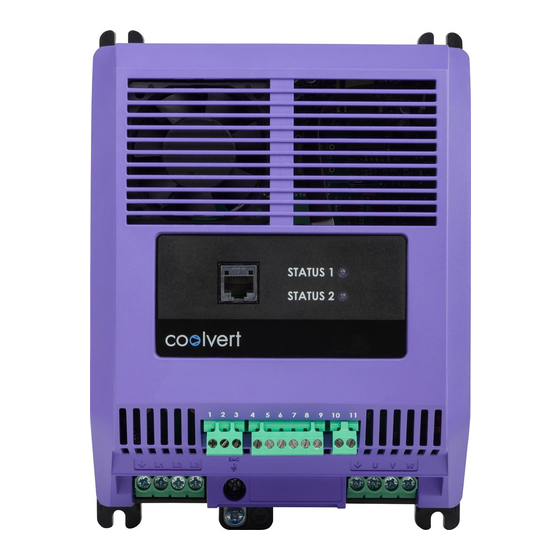
AC Variable Speed Drive
1.5 - 3kW 200V Single Phase Input
5.5 - 1 1kW 400V Three Phase Input
STATUS 1
STATUS 2
1 2 3
4 5 6 7 8 9
EMC
L1 L2 L3
10 11
U
V
W
Important Safety Information
Product Introduction
Installation
Set-up and Operation
Diagnostics
Technical
Specification
Useful Conversions
and Formulae
1
2
3
4
5
6
7
Advertisement
Table of Contents

Related Manuals for Invertek OPTIDRIVE Coolvert


Summary of Contents for Invertek OPTIDRIVE Coolvert
- Page 1 AC Variable Speed Drive 1.5 - 3kW 200V Single Phase Input 5.5 - 1 1kW 400V Three Phase Input Important Safety Information Product Introduction Installation Set-up and Operation Diagnostics Technical STATUS 1 Specification STATUS 2 Useful Conversions and Formulae 1 2 3 4 5 6 7 8 9 10 11 L1 L2 L3...
-
Page 2: Table Of Contents
Installations* ........7. Useful Conversions and Formulae ... 2 | Optidrive CoolVert User Guide | Version 1.00 www.invertekdrives.com... -
Page 3: Important Safety Information
P0-28. User Guide Revision 1.00 Invertek Drives Ltd adopts a policy of continuous improvement and whilst every effort has been made to provide accurate and up to date information, the information contained in this User Guide should be used for guidance purposes only and does not form the part of any contract. - Page 4 Do not attempt to carry out any repair of the Optidrive. In the case of suspected fault or malfunction, contact your local Invertek Drives Sales Partner for further assistance. 4 | Optidrive CoolVert User Guide | Version 1.00...
-
Page 5: Product Introduction
2. Product Introduction The Optidrive Coolvert is a high efficiency variable frequency drive with world-leading motor control performance when operating any of the following motor technologies: Induction Motor Synchronous Permanent Magnet Motor Synchronous Brushless DC Motor Synchronous Reluctance Motor Line Start Permanent Magnet Motor... -
Page 6: Accessories
Fair-Rite round cable snap ferrite 0431 176451), one around the supply cable and the second around the supply earth as detailed in chapter 3.3. EMC Compliant Installation on page 14. 6 | Optidrive CoolVert User Guide | Version 1.00 www.invertekdrives.com... - Page 7 2.2.4. OptiPad – Remote TFT Text LCD Display for commissioning and diagnostics with RJ45 cable OPT-3-OPPAD-IN 2.2.5. Optistick Smart – Bluetooth / PC Interface with Parameter cloning function OPT-3-STICK-IN 2.2.6. Isolated USB to RS485 converter - USB PC Connection Kit OPT-2-USB-OBUS www.invertekdrives.com Version 1.00 | Optidrive CoolVert User Guide | 7...
-
Page 8: Installation
The Optidrive Coolvert should be mounted in a vertical orientation only. The Optidrive Coolvert has been designed to be installed in a suitable enclosure. The drive can be through panel mounted or mounted directly onto the back of a panel using the appropriate mounting kit. - Page 9 NOTE Value 'Z' is not applicable to the coldplate variant. These dimensions are the absolute minimum recommended clearances to allow sufficient air flow. The enclosure itself must be significantly wider or taller than the values given above in at least one direction. www.invertekdrives.com Version 1.00 | Optidrive CoolVert User Guide | 9...
- Page 10 STATUS 1 STATUS 2 1 2 3 4 5 6 7 8 9 10 11 L1 L2 L3 42.6 1.67 3. 1 5 165.3 73.7 8.98 176.2 10 | Optidrive CoolVert User Guide | Version 1.00 www.invertekdrives.com...
- Page 11 3.1.8. Panel mounting the cold-plate variant The Optidrive Coolvert is also available without a heatsink but with a coldplate that needs to be mounted onto a heat transfer surface, removing the drive losses and maintaining the coldplate temperature as shown in the table in section 3. 1 .9. Cold-plate Capacity Calculation on page 1 1.
- Page 12 CV-240140-3FCE +/-10% CV-240140-3FHE 96. 1 % 95.7% 95.5% 94.9% 94.5% 94. 1 % 380-480V CV-240180-3FCE +/-10% CV-240180-3FHE 96.3% 93.2% 95.8% 96.8% 96.7% 96.7% 380-480V CV-240240-3FCE +/-10% CV-240240-3FHE 96.6% 96.5% 96.4% 12 | Optidrive CoolVert User Guide | Version 1.00 www.invertekdrives.com...
-
Page 13: Connection Diagram
Additional information in section 3.3.2. on page 16 This manual is intended as a guide for proper installation. Invertek Drives Ltd cannot assume responsibility for the compliance or the non-compliance to any code, national, local or otherwise, for the proper installation of this drive or associated equipment. -
Page 14: Emc Compliant Installation
The ground terminal of each Optidrive Coolvert should be individually connected DIRECTLY to the site ground bus bar (through the filter if installed). Optidrive Coolvert ground connections should not loop from one drive to another, or to, or from any other equipment. - Page 15 Data in brackets shows permissible cable length with additional external EMC filter. Details of optional external EMC filters listed in section 2.2.2. Optional External EMC Filters on page 6. www.invertekdrives.com Version 1.00 | Optidrive CoolVert User Guide | 15...
- Page 16 The motor earth must be connected to one of the Optidrive earth terminals. Maximum permitted motor cable length for all models: 10 metres shielded, 20 metres unshielded. 16 | Optidrive CoolVert User Guide | Version 1.00 www.invertekdrives.com...
- Page 17 L1 L2 L3 L1 L2 L3 3.3.3. Control Wiring The Optidrive Coolvert has pluggable control terminals to support easy installation. There are three pluggable control terminal blocks split into: S erial Communications (T1-T3) I nputs (T5 – T9) O utput Relay (T10 –...
- Page 18 When using permanent magnet motors and in the unlikely event of a multiple output power devices failing then the motor could effectively rotate the motor shaft by 180/p degrees (Where p denotes number of motor pole pairs). 18 | Optidrive CoolVert User Guide | Version 1.00 www.invertekdrives.com...
- Page 19 The drive should be wired as illustrated below; the 24Vdc signal source applied to the “STO” input can be either from the 24V dc on the drive or from an External 24V dc power supply. www.invertekdrives.com Version 1.00 | Optidrive CoolVert User Guide | 19...
- Page 20 W hen using a motor thermistor connected to the drive analogue input is shown in the diagram, Parameter P3-10 (Modbus register 310) must be set to a value of 8 (PTC). 20 | Optidrive CoolVert User Guide | Version 1.00 www.invertekdrives.com...
-
Page 21: Set-Up And Operation
Acceleration Ramp Time from 0rps to Rated Speed 6000 1-04 Deceleration Ramp Time from Rated Speed to 0rps 6000 5-06 Motor Switching Frequency (24 x max frequency) 5-07 Maximum Torque / Current Limit 1 10 www.invertekdrives.com Version 1.00 | Optidrive CoolVert User Guide | 21... - Page 22 4: Slave Mode 1-05 Stop Mode 0: Ramp to Stop 1: Coast to Stop 2: AC Flux Braking (IM Motor only) 3: Ramp to Minimum Speed then Coast to Stop 22 | Optidrive CoolVert User Guide | Version 1.00 www.invertekdrives.com...
-
Page 23: Modbus Connections
In Modbus mode, the digital input and analogue input can be used as remote I/O by the controller, the relay output can also be configured to be controlled by Modbus and used by the controller if required. www.invertekdrives.com Version 1.00 | Optidrive CoolVert User Guide | 23... - Page 24 STO signal must be provided in order to permit running the motor. Start/Stop command provided by the Digital Input. The speed reference is provided by the output of the PI controller and the PI feedback is provided by the analogue input. P1-11 = 4 Slave mode 24 | Optidrive CoolVert User Guide | Version 1.00 www.invertekdrives.com...
- Page 25 4.2.2. RS-485 Communications Electrical Connections The Optidrive Coolvert has two separate points where you can access the Modbus RTU communications. The Modbus RTU connection can be made via the RJ45 connector or control terminals 1, 2 & 3. As shown below:...
- Page 26 4.2.5. Modbus Telegram Structure The Optidrive Coolvert supports Master / Slave Modbus RTU communications, using the 03 Read Multiple Holding Registers and 06 Write Single Holding Register commands and 16 Write Multiple Holding Registers (Supported for registers 1 – 4 only). Many Master devices treat the first Register address as Register 0;...
- Page 27 B it 4: User Relay Control: Set to 1 to close the onboard relay and set to 0 to open the onboard relay. Note that this function only operates when parameter P3-05 = 6 B it 5: Activate crankcase heating function. Bit 6: Reserved Bit 7: Reserved www.invertekdrives.com Version 1.00 | Optidrive CoolVert User Guide | 27...
-
Page 28: Read-Only Parameter List And Modbus Registers
Motor Speed (IDL Format) Read Only 3000 = 50Hz Motor output voltage Read Only 100 = 100V (AC) P00-1 1 Indirect Parameter Access Index Read/Write Indirect Parameter Access Value Read/Write 28 | Optidrive CoolVert User Guide | Version 1.00 www.invertekdrives.com... - Page 29 P0-32 Run time since last trip (1) Display in hours and minutes since last trip P0-33 Run time since last trip (2) Display in hours and minutes since previous trip www.invertekdrives.com Version 1.00 | Optidrive CoolVert User Guide | 29...
- Page 30 S2…S3 1 = 0.01s with 1dp display as 0.01s~0.09s, 0. 1 s ~9.9s, 10s~600s P0-63 Overload level % of overload level P0-64 Switching frequency internal 4 ~ 32kHz P0-65 Motor control lib version motor control lib version 30 | Optidrive CoolVert User Guide | Version 1.00 www.invertekdrives.com...
-
Page 31: Full Parameter List And Modbus Registers
3: User PI Mode. The drive is enabled by the digital input and the speed is controlled by the internal PI controller. 4: Slave Mode. The drive is enabled by the digital input but the start/stop and speed reference is controlled by the connected Coolvert drive operating in Master mode. www.invertekdrives.com Version 1.00 | Optidrive CoolVert User Guide | 31... - Page 32 Re-start delay time has been observed. The remaining time before the next permitted start can be seen in P0-18. 32 | Optidrive CoolVert User Guide | Version 1.00 www.invertekdrives.com...
- Page 33 P2-05 P2-09 P2-08 Minimum Off Time Sequencing Run CMD Running Status Off time Count-down TIME Minimum Off Time Minimum Off Time KEY: RU Running ST Stopped WR Waiting to Run www.invertekdrives.com Version 1.00 | Optidrive CoolVert User Guide | 33...
- Page 34 RU Running ST Stopped WS Waiting to Stop Re -Start Delay Run CMD Running Status Re -start Countdown TIME Re-start Delay KEY: RU Running ST Stopped WS Waiting to Stop 34 | Optidrive CoolVert User Guide | Version 1.00 www.invertekdrives.com...
- Page 35 P1-1 1 is set to 0 (Modbus control) and P6-05 is set to 3. 3-12 Analogue Input Scaling 2000 Output Value = (Input Value – Offset) x Scaling 3-13 Analogue Input Offset -500 +500 www.invertekdrives.com Version 1.00 | Optidrive CoolVert User Guide | 35...
- Page 36 0: PI loop will run continuously as long as P gain (P4-01) is not zero. 1: PI loop will only run when the drive is enabled. If the drive is not running, the PI output will be reset to 0 (including the integral result). 36 | Optidrive CoolVert User Guide | Version 1.00 www.invertekdrives.com...
- Page 37 If this parameter is set to 1 (Enabled), it will allow a -ve speed reference to be written by serial communications to the drive which will cause reverse speed operation. This setting should be kept as 0 (disabled) if prevention of reverse operation is required. www.invertekdrives.com Version 1.00 | Optidrive CoolVert User Guide | 37...
- Page 38 Controls the behaviour of the drive following a loss of communications. 0: Trip 2: Ramp to stop (No trip) 1: Ramp to Stop then trip 3: Signal Loss speed (P3-11) 38 | Optidrive CoolVert User Guide | Version 1.00 www.invertekdrives.com...
- Page 39 Frequency range for applied boost current (P7-07) as a %age of motor rated frequency (P1-09). This sets the frequency cut-off point above which boost current is no longer applied to the motor. www.invertekdrives.com Version 1.00 | Optidrive CoolVert User Guide | 39...
-
Page 40: Diagnostics
Check the motor wiring S-F Modbus comms loss fault Check the Modbus wiring, ensure that the 0V common is used, ensure that the communication wiring is kept away from any power wiring 40 | Optidrive CoolVert User Guide | Version 1.00 www.invertekdrives.com... -
Page 41: Status Led Indication
Optistick Transfer Fail Fast Flashing 5s Optistick Fail Other Fast Flashing 5s DSP Firmware Upgrade All three LEDs lights up in order (Green->Yellow->Red->Yellow…) IO Firmware Upgrade All LEDs on with weak light www.invertekdrives.com Version 1.00 | Optidrive CoolVert User Guide | 41... -
Page 42: Technical Data
Modbus RTU on Pluggable terminals and through RJ45 port PC Tools PC Tools software for Diagnostics and parameter configuration (RJ45 port only) Keypad Optional Remote Keypad with TFT display for diagnostic and programming 42 | Optidrive CoolVert User Guide | Version 1.00 www.invertekdrives.com... - Page 43 Last 3 trips stored with time stamp Data Logging Logging of data prior to last trip for diagnostic purposes: Output Current Drive Temperature DC Bus Voltage. Monitoring Hours Run Meter www.invertekdrives.com Version 1.00 | Optidrive CoolVert User Guide | 43...
-
Page 44: Detailed Product Rating Tables
6.3. Temperature and Switching Frequency De-rating Requirements for Coolvert 6.3.1 230V Single Phase CV-220070-1FHP / CV-220070-1FCP Maximum continuous output current at ambient temperature Switching Frequency 4 kHz 8 kHz 12 kHz 16 kHz 24 kHz 32 kHz 44 | Optidrive CoolVert User Guide | Version 1.00 www.invertekdrives.com... - Page 45 S upply and motor cable sizes should be dimensioned according to local codes or regulations in the country or area of installation. F or UL compliant installation, use Copper wire with a minimum insulation temperature rating of 70°C, UL Class CC or Class J Fuses. www.invertekdrives.com Version 1.00 | Optidrive CoolVert User Guide | 45...
-
Page 46: Input Power Supply Requirements
50 – 60Hz + / - 5% Variation. 6.5. Additional Information for UL Approved Installations* Optidrive CoolVert is designed to meet the UL requirements. In order to ensure full compliance, the following must be fully observed. Input Power Supply Requirements... -
Page 47: Useful Conversions And Formulae
6000 20400 10200 6300 6300 21600 10800 6600 1 10 6600 1 10 22800 1 1400 6900 1 15 6900 1 15 24000 12000 7200 7200 25200 12600 7500 7500 www.invertekdrives.com Version 1.00 | Optidrive CoolVert User Guide | 47... - Page 48 Ñ82-COOLV-IN_V1.004Ó 82-COOLV-IN_V1.00 Invertek Drives Ltd. Offa's Dyke Business Park, Welshpool, Powys SY21 8JF United Kingdom Tel: +44 (0)1938 556868 Fax: +44 (0)1938 556869 www.invertekdrives.com...
Need help?
Do you have a question about the OPTIDRIVE Coolvert and is the answer not in the manual?
Questions and answers