Table of Contents
Advertisement
Quick Links
Download this manual
See also:
Installation Manual
Advertisement
Table of Contents
Troubleshooting

Related Manuals for Parker PAC


Summary of Contents for Parker PAC
- Page 1 PARKER AUTOMATION CONTROLLER PAC Installation Guide © 2014 Parker Hannifin Corporation All Rights Reserved...
-
Page 2: Trademark Information
IMPORTANT USER INFORMATION Trademark Information The Programmable Logic Controller and PLC are registered trademarks of the Allen-Bradley Company ® ® (Rockwell Automation). EtherCAT is a registered trademark and a patented technology of Beckhoff Automation GmbH, Germany. ® CoDeSys is a registered trademark of 3S-Smart Software Solutions GmbH. ®... -
Page 3: Important User Information
Important User Information Please read and follow all safety information for the Parker Automation Controller (PAC), including the warning and caution statements in this guide, before installing or operating the system. Safety Information WARNING: The PAC is used to control electrical and mechanical components of motion control systems in industrial environments. - Page 4 Parker or its subsidiaries or authorized distributors. To the extent that Parker or its subsidiaries or authorized distributors provide component or system...
- Page 5 Parker Installation Guidelines described in this document offer information regarding how to install the PAC in a manner most likely to minimize the effects of drive emissions and to maximize the immunity of the PAC from externally generated interference. Compliance of the PACIO Modules is demonstrated by the application of the following standard: 2004/108/EC Electromagnetic Compatibility when installed, operated, and maintained as intended.
- Page 6 The PAC must be mounted in a suitable tool accessed, fire enclosure. PAC input power is rated at: 24 VDC (-15%/+25%) SELV Limited Energy, 1.2 A, 29W. External power to the PAC must be provided by a Class 2 power source. For customer convenience, Parker offers an AC-input, Model PS-60W, Class 2, 24VDC power supply, which is available for purchase, to provide power to the PAC and PACIO Modules.
-
Page 7: Table Of Contents
Configuring the Network and System Settings ................... 41 Configuring the Compax3 EtherCAT slave node ..................57 Downloading and Uploading a Project to the PAC ..................59 Programming your Xpress HMI in the PAC ....................64 CHAPTER 4: PACIO Modules ....................... 69 PACIO Module Overview .......................... - Page 8 Log Files ..............................185 I/O Modules ..............................186 HDMI Connector ............................186 Real Time Clock (RTC) ..........................186 APPENDIX A: PAC System Specifications ..................189 Controller Specifications ..........................190 PACIO Technical Data ..........................194 APPENDIX B: Additional Information ....................195 Terms and Acronyms ..........................
-
Page 9: About This Guide
Update the SD card note from 4Gb to 32Gb (pg 185) Assumptions of Technical Experience Parker Hannifin Corporation assumes you are qualified in the servicing of industrial control systems, and trained in recognizing hazards in products with hazardous energy levels. To install and troubleshoot the... - Page 10 CAUTION: A caution provides information intended to help prevent malfunction of the product or damage to the product hardware or software. NOTE: A note provides information intended to help you make the best use of your product from Parker Hannifin Corporation. Parker Automation Controller Installation Guide...
-
Page 11: Chapter 1: Product Overview
CHAPTER 1: Product Overview... -
Page 12: Product Description
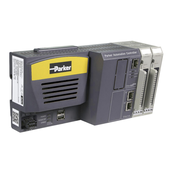
The PAC operating system and runtime software reside on a standard Secure Digital (SD) memory card inserted into a slot at the top of the PAC. LED indicators on the PAC front panel help you to monitor and its installation requires only a small screwdriver. -
Page 13: Product Features
Product Features Overall, the PAC System consists of the Controller, PACIO Modules, and an optional communication module. The following sections highlight the various features of the PAC. Features of the PAC and PACIO Modules Number Feature Name Description PAC Controller... - Page 14 ) indicate the system status USB Ports Dual standard USB 2.0 ports, type A SD Card Parker removable SD (or SDHC) memory card Button Push button used for logging the IP address HDMI Connector Not Functional, for Factory Use Only...
- Page 15 PACIO Module Features For the basic layout of the PACIO Modules see the illustration below. The PACIO Modules consist of a plastic housing and an internal aluminum profile with an integral mechanism to snap the Module to a 35mm DIN rail. The PACIO Modules differ from one another in their functionality, connectors and indicators.
- Page 16 Its interconnections among the PAC at one end, and both the I/O Modules and drives at the other, are as fast as those of a backplane bus. An EtherCAT-connected I/O bus acts much like centralized control systems, overcoming the issue of bus transfer times that burden conventional fieldbus systems.
- Page 17 Controller to each of the Modules is via an internal EtherCAT E-Bus network. The first PACIO Module plugs into the E-Bus connector on the PAC Controller, and each additional Module plugs in to the proceeding Module, making a chain of up to 20 interconnected Modules. You choose from a variety of PACIO Modules to add, based on the requirements of your specific application.
-
Page 19: Chapter 2: Installation
CHAPTER 2: Installation... -
Page 20: Checking Your Shipment
88-032477-01 Required Tools Installing the PAC and PACIO Modules on the DIN rail requires no tools. However, a small flat blade screwdriver (tip size 0.04mm x 2.5mm) is required for attaching the wiring to the PAC Controller and PACIO Modules. - Page 21 Important: A Limited Power Source (LPS) power supply or circuit according to IEC 60950-1, or an NEC Class 2 power source must be used to provide power to the PAC. NEC Class 2 circuits are considered to be safe from a fire ignition standpoint and provide acceptable protection against electric shock.
-
Page 22: Installation Overview
INSTALLATION Installation Overview The illustration below shows the components that you need to install the PAC. It shows the Controller connected to multiple PACIO Modules. The recommended installation process follows. Basic Installation Steps The following steps give a high-level overview of the installation process. See the remainder of the chapter for additional details on completing each step. -
Page 23: Installation Guidelines
EMI considerations. Regulatory Installation Guidelines The PAC System is designed for use in industrial environments. It is to be installed in an industrial enclosure and factory wired according to National Electric Code (NEC) guidelines. When installing the Controller and PACIO, you can either use a 24VDC Limited Power Source (LPS) or Class 2 power circuit available in the control cabinet, a purchased LPS or Class 2 power supply, or an optional Parker model PS-60W Class 2 power supply, purchased separately. - Page 24 Allow a minimum of two inches between the inside of the enclosure and the top, bottom, and sides of the PAC. Verify that the surface of the enclosure on which the PAC is mounted is flat and free of raised or depressed areas.
- Page 25 (IEC/EN61010-1). To reduce radiated emissions, ensure that there is a low impedance earth connection to the PAC, which can be accomplished by attaching the DIN rail to a suitable Earth ground and also utilizing Pin-3 on the Controller 24VDC power input connector. This connection must be made with the shortest possible, heavy gage wire or braided cable.
- Page 26 Calculate the overall length of DIN rail required for the installation base on the following component widths. Be sure to include extra length for adding additional modules in the future and a clearance allowance for removing modules. Parker Automation Controller Installation Guide...
-
Page 27: Mounting The Controller
Mounting the Controller To mount the PAC Controller to the DIN Rail: 1. Push the module up against the mounting rail from below, allowing the metal spring to snap in between the mounting rail and mounting area. 2. Push the module against the mounting wall until it snaps into place. -
Page 28: Removing The Controller
Damage to the modules or unintended I/O functionality might occur. Earth Ground Just as with the PAC Controller, connect the PACIO Modules to Earth by attaching the metal housing to operative Earth via the grounded DIN rail. Parker Automation Controller Installation Guide... - Page 29 Check all connections to verify that: The connection between the PACIO Module housing and DIN rail conducts well. The connection between the DIN rail and control cabinet conducts well. The control cabinet is connected to Earth. ...
- Page 30 Note: To ensure smooth functionality of the PACIO modules, the PACIO modules must be arranged based on their e-bus load. The modules with the biggest e-bus load are to be arranged directly next to the PAC Controller. The modules with the smallest e-bus load should be the furthest from the PAC.
- Page 31 To Remove a PACIO Module from the PAC Controller 1. Press the Unlock Button on the PACIO Module that needs to be removed, and slide all modules about 2 cm to the right. 2. Push the Unlock Button on the adjacent Module to the right of the Module to be removed and slide the Module that needs to be removed to the left, just enough to clear the E-Bus connector on the right Module.
-
Page 32: Attaching Cables
INSTALLATION Fieldbus Communication Module (optional) An optional Fieldbus Communication Module is available with the PAC Controller in order to provide PROFINET I/O data via a PCI Express interface. Refer to Chapter 6 for more information on the configuration or installation of the PROFINET Slave option. -
Page 33: Chapter 3: System Start-Up And Configuration
CHAPTER 3: System Start-up and Configuration... -
Page 34: Overview Of System Start-Up
Overview of System Start-up Once the installation location has been properly determined and the PAC Controller and PACIO Modules have been mounted to the DIN rail and properly grounded, it is time to apply power and configure the PAC Controller. - Page 35 Connection Diagram For convenience, the 24VDC input connector can be prewired and then plugged into the mating connector on the unit. Remember to tighten the two screws located on each side of the connector to prevent unintended disconnection. CAUTION: To reduce issues associated with noise on the input DC power, keep the 24VDC wiring away from any AC interfering sources, such as motor leads or other devices, and keep the wiring as short as possible.
- Page 36 CAUTION: Permanently connected equipment must include a switch or circuit breaker between the Controller and power source. This disconnect must be in a suitable location within reach of the Controller and must be properly marked to indicate that its purpose is to disconnect power. Parker Automation Controller Installation Guide...
- Page 37 4.88 x 1.97 x 4.55 (124 x 50 x 116mm) If you provide your own machine power or a separate AC/DC power supply, the nominal input to the PAC Controller and up to approximately 20 PACIO Modules is 24VDC @ 1.2A or a total of 29 Watts.
- Page 38 1. Push a small screwdriver (tip size 0.04mm x 2.5mm) into the small square opening on the back of the connector. 2. Insert the stripped wire (<10mm) into the adjacent rectangular opening on the connector. 3. Remove the screwdriver. 4. Gently tug on the wire to confirm that it is tightly captured. Parker Automation Controller Installation Guide...
- Page 39 PACIO Power Distribution Module Many PACIO Modules require 24VDC to provide power to field outputs. To ensure that there is as little cross interference as possible, do not connect the PACIO field power supply lines from one PACIO power supply port to the next. Install a central power supply point and establish a star topology using the shortest wires possible between the central point and PACIO Modules.
- Page 40 SYSTEM START-UP AND CONFIGURATION Apply power to the PAC for the First Time Once the following steps have been completed, 24VDC can be applied to the Controller and PACIO Modules: PAC Controller has been mounted to a DIN rail ...
-
Page 41: Configuring The Network And System Settings
Configuring the Network and System Settings Upon powering the system for the first time, use the PAC Configuration Tool to configure the initial system parameters. After commissioning the machine, these parameters need to be changed. To run the PAC Configuration Tool located in the PAC Controller, perform the following steps: 2. - Page 42 Click on the [?] button at the upper right corner of the page to display online help at any time to learn more about using the PAC Configuration Tool. This tool is useful for setting or changing the Controller system parameters.
- Page 43 TIP: If more than one PAC Controller is connected to the same network, each Controller must be assigned a unique IP address to avoid network conflicts. Also confirm that the IP addresses of the PAC Controller(s) do not conflict with any other devices on the same network Tab 2 –...
- Page 44 SYSTEM START-UP AND CONFIGURATION Tab 4 – Xpress HMI Settings This tab is used for the Xpress HMI option on the PAC. It allows the user to launch the Xpress Shell and Upload/Download Xpress projects. Parker Automation Controller Installation Guide...
- Page 45 Configuring the PAC with the Parker Automation Manager Software The Parker Automation Manager Software package is used to configure the PAC as the EtherCAT master and to program the PAC with the IEC611-31 language. The Parker Automation Manager software can be downloaded from parkermotion.com under the PAC product page or in the Support and Downloads page.
- Page 46 5. Choose Add Device. This will add the PAC320 to your device tree. 6. Choose the PLC_PRG language you would like to use in your project. Choose OK. 7. The PAC will now show up in the Device Tree and you are now ready to start building your project with the PAC.
- Page 47 8. The Help menu in Parker Automation Manager is a great resource with documentation to help you start programming your project.
- Page 48 SYSTEM START-UP AND CONFIGURATION Connection to the PAC The following section will step you through the process to connect Parker Automation Manger to the PAC section. Device (PAC320-MXX2X-XX) Under the Communications Settings tab, select Scan Network. 2. After the scanning process finds the PAC, select the PAC and click OK.
- Page 49 If your PAC will only be used with the PACIO Modules, the use of distributed clocks is not required. But if you are using the PAC with a servo drive such as the Compax3, then these steps are required.
- Page 50 4. Check the Sync Window Monitoring checkbox and set the Sync window to 50. Configuration of the PACIO (Online Method) 1. Ensure that you are connected to the PAC (See Connection to the PAC). 2. Right- EtherCAT_Master (PAC320 EtherCAT Master)
- Page 51 3. A list of connected EtherCAT slaves will be displayed. If this list is missing a slave, ensure the slave is connected and powered on, and then click the Scan for Devices button to re-scan. 4. When the list is complete, Copy all devices to project and the PACIO will show up on your device tree under the PAC320_BusCoupler.
- Page 52 Configuration of the PACIO (Online Method) After you have configured the PAC as an EtherCAT master, you can now add your PACIO Modules as slaves under the PAC320_BusCoupler. You can add the modules to the project without having an Ethernet connection to the PAC.
- Page 53 3. The new module appears in the list. You can continue to append more PACIO Modules as needed to match your hardware by repeating these steps.
- Page 54 3. Double click in the Variable column for the desired IO point and create a name for this point. *Note: Variables created this way are global for the project. The IO Point can now be accessed in any POU through the variable name. Parker Automation Controller Installation Guide...
- Page 55 Copy to project. 4. The dialog sets the default name "Compax3_EtherCAT_DS402_CoE_". The Compax3 is now added as a slave to the PAC in the project. 5. Notice that along with the "Compax3_EtherCAT_DS402_CoE" EtherCAT slave device, the axis is created. Right-click on the SM_Drive_ETC_Parker node and...
- Page 56 Rename. Change the name as appropriate. This will also be the main name used for the SoftMotion Function blocks. 6. Go to the menu Online and select the Logout item to go offline with the PAC and continue configuration in the Configuring the Compax3 EtherCAT slave node section Add the Compax3 as an EtherCAT slave (Offline Method) 1.
-
Page 57: Configuring The Compax3 Ethercat Slave Node
6. Click Add Device. 7. In the Devices tree, the C3SxxxVxFxxI31T11Mxx_OpMode8 V2.05 SoftMotion node is added under the EtherCAT_Master node. Compax3_EtherCAT_DS402_CoE -click on the SM_Drive_ETC_Parker node and select Rename. Change the name as appropriate. This will also be the main name used for the SoftMotion Function blocks. - Page 58 Compax3 Servo Manager and are in drive input counts per motor revolution, regardless of the feedback counts of the motor. Your Compax3 is now configured as an EtherCAT Slave with the PAC. Parker Automation Controller Installation Guide...
-
Page 59: Downloading And Uploading A Project To The Pac
1. To download the project execution code, select the Login Icon on the Toolbar. 2. You may be prompted to find an active path. To have the PAC automatically scan, select Yes. To open the Communications Settings Page, select No and then proceed to scan the network for the... - Page 60 SYSTEM START-UP AND CONFIGURATION 3. If there is a project already on the PAC and you want to replace it with this application, click Yes. 4. If you are downloading the project the first time to a PAC without a project, it may prompt you with a pop up window asking if you want to download the application, click Yes.
- Page 61 To upload a project from the PAC, use the following instructions to help with this process: 1. In Parker Automation Manger select FileSource Upload. 2. Select the PAC on the Gateway and select OK. If a PAC does not show up on the Gateway, select Scan network.
- Page 62 Your project and source files are now saved to your computer. 4. If you would like to open the project, click Yes. Your project and source files are now opened in Parker Automation Manager. Opening a PAM 1.2.1 project in PAM 1.3.0 PAM 1.3 will allow a user to open either a PAM 1.2.1 project or a PAM 1.3.0 project.
- Page 63 3. From the Devices Tree - This will tell the project to use the PAM 1.3 Device Description for the PAC Device. 4. Update any other device in the tree to make sure the latest Device Description is used in the...
-
Page 64: Programming Your Xpress Hmi In The Pac
PAC product page on www.parkermotion.com. The PAC with the embedded Xpress HMI option allows you to easily share tags between the two projects to make it easier to create your application. Any POU, Global Variable, or Persistent list in your PAC project can share tags with Xpress. - Page 65 This will expose them for use with the Xpress HMI. Note: In order to expose your tags to Xpress, you must check the box for each tag. Any POU, Global Variable, or Persistent list in your PAC project can share tags with Xpress 9. Save the project.
- Page 66 Choose Yes. This will download the PLC project to the PAC and allow the variables to be accessed by Xpress. To develop your Xpress project on the PAC and access the tags from your PAC program, follow these instructions: 11. Launch a Web Browser.
- Page 67 16. Interact Xpress Designer loads. Press the Tags Tab. The Variables are now accessible tags in the Xpress HMI. Note: Not all data types are allowed to be shared to your PAC project. The data types NOT allowed are: TIME, DATE, BITORBYTE, TOD, DT, REF, VOID, LTIME, BIT.
- Page 68 SYSTEM START-UP AND CONFIGURATION To help program your Xpress project, refer to the Interact Xpress user guide that can be downloaded from the Interact Xpress Manager product page on line at address: http://www.parkermotion.com/products/Dedicated_HMI__7223__30_32_80_567_29.html Parker Automation Controller Installation Guide...
-
Page 69: Chapter 4: Pacio Modules
CHAPTER 4: PACIO Modules... -
Page 70: Pacio Module Overview
Modules, counters and interface Modules. Each of the PACIO Modules listed in the table below are compatible with the PAC. See the remainder of this chapter for details about each Module To order, contact your local Automation Technology Center (ATC) or distributor. -
Page 71: Pacio-400-00 - Bus Coupler 3A
PACIO-400-00 - Bus Coupler 3A Although a bus coupler is built in to the PAC, the PACIO Bus Coupler 3A Module serves as a bus for remote I/O modules. It converts CAT5e (twisted pair cable) to a low-voltage differential signaling (LVDS) E-Bus and also provides the system power required by the remote PACIO modules. - Page 72 Module State Variable Data Type Explanation Undervoltage BOOL Low voltage (supplied power < 19.2V) Terminals Module Power Supply 24 VDC EtherCAT RJ45 socket input (from previous EtherCAT station) RJ45 socket output (to next EtherCAT station) Parker Automation Controller Installation Guide...
- Page 73 Status LEDs The LED labeled "EtherCAT Run" indicates the state of the EtherCAT indicate the physical state of the Ethernet ports to which they are allocated. State LED Flash Code Explanation Init Initializing, no data exchange Pre-Op Off/green, 1:1 Pre-operational, no data exchange Safe-Op Off/green, 5:1 Safe operation, inputs readable...
-
Page 74: Pacio-450-02 - Di16/Do8 1A
Max Input Frequency 200 Hz Off: - -2, type 1) Signal Level Typical current draw of 5 mA per input at 24V Output Specs Digital Outputs 1A per output Maximum Current Total Current Maximum 8A Parker Automation Controller Installation Guide... - Page 75 Variable Variable Data Type Explanation DigitalInputn BOOL Digital input (n=0...15) DigitalOutputn BOOL Digital output (n=0...7) reserved BOOL Unused output addresses Terminals Module Power Supply 24 VDC NOTE: Connect L+ to both L+ terminals if the total current exceeds the 6A limit. L+ and L- on both the inputs and outputs are internally connected.
- Page 76 CAUTION: The output drivers have a thermal fuse to automatically turn off any short-circuited outputs. If a short circuit occurs, remove the fault and allow the output to cool down and reset before reenergizing the system. Parker Automation Controller Installation Guide...
-
Page 77: Pacio-450-03 - Di16/Do16 1Ms/0.5A
PACIO-450-03 - DI16/DO16 1ms/0.5A The PACIO DI16/DO16 1ms/0.5A Module features 16 digital inputs and 16 digital outputs. Technical data PACIO DI16/DO16 1ms/0.5A Part number PACIO-450-03 Controller ASIC ET1200 Baud Rate 100 Mbit/s Power Supply 24 VDC -20% +25% E-Bus Load 135mA Connector IO/Power Plug 36-pole (43-026592-01) - Page 78 CAUTION: The output drivers have a thermal fuse to automatically turn off any short-circuited outputs. If a short circuit occurs, remove the fault and allow the output to cool down and reset before reenergizing the system. Parker Automation Controller Installation Guide...
-
Page 79: Pacio-450-05 - Di8/Do8 1Ms/0.5A
PACIO-450-05 - DI8/DO8 1ms/0.5A The PACIO DI8/DO8 1ms/0.5A Module has 8 digital inputs and 8 digital outputs. Technical Data PACIO DI8/DO8 1ms/0.5A Part number PACIO-450-05 Connector IO/Power Plug 18-pole (43-026591-01) Controller ASIC ET1200 Baud rate 100 Mbit/s Power supply 24 VDC -20% +25% E-Bus load 135mA Digital inputs... - Page 80 CAUTION: The output drivers have a thermal fuse to automatically turn off any short-circuited outputs. If a short circuit occurs, remove the fault and allow the output to cool down and reset before reenergizing the system. Parker Automation Controller Installation Guide...
-
Page 81: Pacio-450-13 - Di16/Do16 1Ms/0.5A Ls (Sinking)
PACIO-450-13 - DI16/DO16 1ms/0.5A LS (Sinking) The PACIO DI16/DO16 1ms/0.5A LS Module features 16 digital low-side inputs and 16 digital low-side outputs. Technical Data PACIO DI16/DO16 1ms/0.5A LS Part number PACIO-450-13 Connector IO/Power Plug 36-pole (43-026592-01) Controller ASIC ET1200 Baud rate 100 Mbit/s Power supply 24 VDC -20% +25%... - Page 82 CAUTION: The output drivers have a thermal fuse to automatically turn off any short-circuited outputs. If a short circuit occurs, remove the fault and allow the output to cool down and reset before reenergizing the system. Parker Automation Controller Installation Guide...
-
Page 83: Pacio-451-02 - Di32 1Ms
PACIO-451-02 - DI32 1ms The PACIO DI32 1ms Module features 32 digital inputs. Technical Data PACIO DI32 1ms Part number PACIO-451-02 Connector IO/Power Plug 36-pole (43-026592-01) Controller ASIC ET1200 Baud rate 100 Mbit/s Power supply 24 VDC -20% +25% E-Bus load 85 mA Inputs Specs Digital inputs... - Page 84 Initializing, no data exchange Pre-Op Off/green, 1:1 Pre-operational, no data exchange Safe-Op Off/green, 5:1 Safe operation, inputs readable Green, on Operational, unrestricted data exchange Channel State State State Green, on Input signal = TRUE Input signal = FALSE Parker Automation Controller Installation Guide...
-
Page 85: Pacio-451-03 - Di16 1Ms
PACIO-451-03 - DI16 1ms The PACIO DI16 1ms Module has 16 digital inputs. Technical Data PACIO DI16 1ms Part number PACIO-451-03 Connector IO/Power Plug 18-pole (43-026591-01) Controller ASIC ET1200 Baud rate 100 Mbit/s Power supply 24 VDC -20% +25% E-Bus load 100 mA Input Specs Digital inputs... - Page 86 Initializing, no data exchange Pre-Op Off/green, 1:1 Pre-operational, no data exchange Safe-Op Off/green, 5:1 Safe operation, inputs readable Green, on Operational, unrestricted data exchange Channel State State State Green, on Input signal = TRUE Input signal = FALSE Parker Automation Controller Installation Guide...
-
Page 87: Pacio-452-01 - Do16 0.5A
PACIO-452-01 - DO16 0.5A The PACIO DO16 0.5A Module features 16 digital outputs. Technical Data PACIO DO16 0.5A Part number PACIO-452-01 Connector IO/Power Plug 18-pole (43-026591-01) Controller ASIC ET1200 Baud rate 100 Mbit/s Power supply 24 VDC -20% +25% E-Bus load 130mA Output Specs Digital outputs... - Page 88 CAUTION: The output drivers have a thermal fuse to automatically turn off any short-circuited outputs. If a short circuit occurs, remove the fault and allow the output to cool down and reset before reenergizing the system. Parker Automation Controller Installation Guide...
-
Page 89: Pacio-452-02 - Do8 1A
PACIO-452-02 - DO8 1A The PACIO DO8 1A Module features 8 digital outputs. Technical Data PACIO DO8 1A Part number PACIO-452-02 Connector IO/Power Plug 18-pole (43-026591-01) Controller ASIC ET1200 Baud rate 100 Mbit/s Power supply 24 VDC -20% +25% E-Bus load 130mA Output Specs Digital outputs... - Page 90 CAUTION: The output drivers have a thermal fuse to automatically turn off any short-circuited outputs. If a short circuit occurs, remove the fault and allow the output to cool down and reset before reenergizing the system. Parker Automation Controller Installation Guide...
-
Page 91: Pacio-441-01 - Ai4-Ma 12 Bit
PACIO-441-01 - AI4-mA 12 Bit The PACIO AI4-mA 12 Bit Module offers 4 analog current signal inputs. Their measuring range can be set separately for every channel (that is, either to 0-20mA or to 4-20mA). Technical Data PACIO AI4-mA 12 Bit Part number PACIO-441-01 Analog inputs... - Page 92 Module Defective Red, on Module Defective Power State LED Flash Code Explanation Green, on 24 VDC supply ok 24 VDC supply not ok State LED Flash Code Explanation Green, on Channel enabled Output disabled Parker Automation Controller Installation Guide...
- Page 93 Analog Inputs Check the following variable for the digitized input values. Variable Data type Explanation Channel_n Measured Value The maximal measuring value (0xFFF0) The status is shown by the channel LED. Analog Values Current Measuring Variable Values Measuring Variable Values Decimal Hexadecimal Decimal...
- Page 94 Short circuit Undervoltage BOOL Low voltage (supplied power < 19.2V) Watchdog BOOL Internal watchdog of module EtherCAT_Error BOOL Configuration error or watchdog control Specific_Error BOOL Module-specific fault OptionsSet BOOL Sent by module to acknowledge SetOptions Parker Automation Controller Installation Guide...
- Page 95 0.55 0.69 NOTE: If you are aiming for a high sampling frequency, the PAC should do the filtering (averaging) because it will normally have much more processing power. Take the EtherCAT cycle into account to assess how much the values stored by the EtherCAT master are up-to-date.
- Page 96 PACIO MODULES current Connector sensor (ext.) channel n NOTE: Best results are obtained by connecting the shield of the signal cables to operative earth. Parker Automation Controller Installation Guide...
-
Page 97: Pacio-441-02 - Ai4/8-Vdc 13 Bit
PACIO-441-02 - AI4/8-VDC 13 Bit The PACIO AI4/8-VDC 13 Bit Module features eight analog inputs. If signal lines are single-ended (measured against earth, L-), eight channels are available. To measure differential signals, you need two channels for every signal (that is, you can pick up no more than four differential signals). Channels can be combined as follows: 0/1, 2/3, 4/5, and 6/7. - Page 98 Module Defective Red, on Module Defective State LED Flash Code Explanation Green, on Channel enabled Channel disabled Analog inputs Check the following variable for the digitized input values. Variable Data type Explanation Channel_n UINT Parker Automation Controller Installation Guide...
- Page 99 Analog Voltage Values Measuring Variable Value Bipolar Unipolar Volt Decimal Hexadecimal Decimal Hexadecimal 32768 16#8000 36044 16#8CCC 39321 16#9999 42598 16#A666 45875 16#B333 49152 16#C000 52428 16#CCCC 55705 16#D999 58982 16#E666 62244 16#F324 3276 16#0CCC 6553 16#1999 6553 16#1999 13107 16#3332 9830 16#2666...
- Page 100 The cycle consists of the analog value conversion plus transmitting the values into the EtherCAT data area. Number of channels Cycle time in ms Number of channels Cycle time in ms 270µs 630µs 360µs 710µs 450µs 800µs 540µs 890µs Parker Automation Controller Installation Guide...
- Page 101 NOTE: If you are aiming for a high sampling frequency, the PAC should do the filtering (averaging) because it will normally have much more processing power. Take the EtherCAT cycle into account to assess how much the values stored by the EtherCAT master are up-to-date.
-
Page 102: Pacio-443-06 - Ai8 Thermocouple 16 Bit
The PACIO AI8 Thermocouple 16 Bit Module does not need a separate 24V connector. Power is supplied to the Module through the E-Bus connector. For information on operative earth shielding of analog wire, see Earth Grounding Guidelines international electromagnetic and emission standards. To reduce radiated emissions, ensure that there is Parker Automation Controller Installation Guide... - Page 103 PAC, which can be accomplished by attaching the DIN rail to a suitable Earth ground and also utilizing Pin-3 on the Controller DC power input connector. This connection must be made with the shortest possible, heavy gage wire or braided cable. Low-resistance (<0.5 ohms) continuity should be verified with an ohmmeter for proper grounding.
- Page 104 16#04 Type K: not used 16#14 Type K: -200°C .. +1372°C in 0.1°C Channel_n_On BOOL Enables channel n Set filter for channel n. Channel_n_Filter USINT The arithmetic mean is output after n+1 conversions Channel number Parker Automation Controller Installation Guide...
- Page 105 Number of channels Cycle Time in ms NOTE: If you are aiming for a high sampling frequency, the PAC should do the filtering (averaging) because it will normally have much more processing power. Take the EtherCAT cycle into account to assess how much the values stored by the EtherCAT master are up-to-date.
- Page 106 PACIO MODULES Quality of Analog Values Best results are obtained by: Connecting the shield of the signal cables to operative earth Connecting unused single-ended lines to Ground Short-circuiting unused differential inputs Parker Automation Controller Installation Guide...
-
Page 107: Pacio-442-02 - Ao4-Vdc/Ma 12 Bit
PACIO-442-02 - AO4-VDC/mA 12 Bit Channel Channel0 Channel1 Channel2 Channel3 The PACIO AO4-VDC/mA 12 Bit Module features four analog outputs. Every channel can be separately set to the unipolar or bipolar output of voltages or currents. Technical Data PACIO A04-VDC/mA 12 Bit Part number PACIO-442-02 Analog inputs... - Page 108 Pre-operational, no data exchange Safe-Op Off/green, 5:1 Safe operation, inputs readable Green, on Operational, unrestricted data exchange State LED Flash Code Explanation Green, on No error Error Malfunction of Module if E-Bus LED = On Parker Automation Controller Installation Guide...
- Page 109 Inoperative if E-Bus LED = Off Red, 1x Short circuit Red, 2x Low voltage Red, 4x EtherCAT watchdog control Red, 6x Module-specific fault Configuration error (E-Bus pre-operational), number of process data Red, 7x differs from that in the Module Defective Red, on Module defective Power...
- Page 110 16#1999 13107 16#3332 9830 16#2666 19660 16#4CCC 13106 16#3332 26214 16#6665 16383 16#3FFF 32767 16#7FFF 19660 16#4CCC 39320 16#9998 22936 16#5998 45874 16#B332 26213 16#6665 52427 16#CCCB 29490 16#7332 58981 16#E665 32767 16#7FFF 65534 16#FFFE Parker Automation Controller Installation Guide...
- Page 111 Module control The Module provides you with various operational options. To set up the Module, choose the options as appropriate and accept by setting control bit "SetOptions" to a rising edge. The Module will confirm by returning "OptionsSet". There are various "Module error" bits that the Module uses to indicate errors. The states of the error bits are retained and also used for error indication by the "IO"...
- Page 112 The PACIO AO4-VDC/mA 12 Bit Module has a set cycle time of 320µs that is not affected by the number of active channels. The cycle time is the time between receipt of the output values and the start of the D/A converters. Parker Automation Controller Installation Guide...
-
Page 113: Pacio-443-01 - Ai4-Pt/Ni100 16 Bit
PACIO-443-01 - AI4-Pt/Ni100 16 Bit PACIO-443-03 - AI4-Pt/Ni1000 16 Bit The PACIO AI4-Pt/Ni100 16 Bit Module has 4 analog inputs for Pt100 or Ni100 temperature sensors. It also can measure resistances between 70 and 330 . The PACIO AI4-Pt/Ni1000 16 Bit Module has 4 analog inputs for Pt1000 or Ni1000 temperature sensors. - Page 114 To reduce radiated emissions, ensure that there is a good earth connection to the PAC, which can be accomplished by attaching the DIN rail to a suitable Earth ground and also utilizing Pin-3 on the Controller DC power input connector.
- Page 115 Red, 6x Module-specific fault Configuration error (E-Bus pre-operational), number of process data Red, 7x differs from that in the Module Defective Red, on Module defective State LED Flash Code Explanation Green, on Channel enabled Channel disabled Error Short circuit, Broken wire Analog Inputs NOTE: The letter in the following tables...
- Page 116 Analog value conversion runs cyclically and is not synchronized with the receipt of EtherCAT telegrams. The cycle consists of the analog value conversion plus transmitting the values into the EtherCAT data area. Number of Channels Cycle Time in ms Parker Automation Controller Installation Guide...
- Page 117 NOTE: If you are aiming for a high sampling frequency, the PAC should do the filtering (averaging) because it will normally have much more processing power. Take the EtherCAT cycle into account to assess how much the values stored by the EtherCAT master are up-to-date.
-
Page 118: Pacio-454-01 - Counter/Enc
Typical current draw of 5 mA per input at 24V Output Specs Digital outputs 2A per output Maximum current Analog Output Specs Analog outputs Voltage ±10V Resolution 12 bit Fieldbus EtherCAT 100 Mbit/s EtherCAT-File ParkerEtherCATModules.xml Dimensions (WxHxD) 25x120x90 mm Parker Automation Controller Installation Guide... - Page 119 To reduce radiated emissions, ensure that there is a good earth connection to the PAC, which can be accomplished by attaching the DIN rail to a suitable Earth ground and also utilizing Pin-3 on the Controller DC power input connector. This connection must be made with the shortest possible, heavy gage wire or braided cable.
- Page 120 The Status LEDs of the several IOs indicate the state of the individual I/Os. Status LEDs of I/Os Voltage Color Explanation 0..3 Green Digital Inputs Green Digital Outputs 7, 9, 11 Green Encoder signals A, B, Ref Parker Automation Controller Installation Guide...
- Page 121 Function The PACIO Counter/Enc Module has two identical channels. Each channel has terminals for one encoder, four digital inputs, one digital output, and one analog output. The documentation organizes the variables into structured groups: Module Control/Module Status for controlling and monitoring the entire module. ...
- Page 122 The Module offers different options for the operation of Counters. The options are set in the Module with the help of the control bit "SetOptions_1" (see also ) and then remain valid until the next setting procedure. 1. Set the variables for the desired configuration. 2. Set "SetOptions_1=FALSE" and then set "SetOptions_1=TRUE". Parker Automation Controller Installation Guide...
- Page 123 The Module indicates the execution with "OptionsSet_1=TRUE". When "SetOptions_1" becomes FALSE again, the Module responds with "OptionsSet_1=FALSE". This indicates that the Module is ready for the next setting procedure. Variable Data type Value Explanation Deactivate compare function Enable_Compare_1 BOOL Activate compare function A, B, Ref with detection of direction SelectEncoder_1 BOOL...
- Page 124 BOOL Copy "SetValue_1" to the current counter value SetCompare_1 BOOL Copy "SetValue_1" to the compare value register SetPreset_1 BOOL Copy "SetValue_1" to the preset value register SetMax_1 BOOL Copy "SetValue_1" to the maximum value register Parker Automation Controller Installation Guide...
- Page 125 The current set values can be read in the variable "SelectedValue" from the group. Use the variable "Select_1",to determine which value you want to see in the variable "SelectedValue"(see section Counter Actual Values ). Variable Data type Explanation Sets the value displayed in the variable "SelectedValue_1": none Compare value Preset value...
- Page 126 Time stamp for Digital Input 0 (Hardware Triggered) Input_1_1_TS UINT Time stamp for Digital Input 1 (Software Polled) Input_1_2_TS UINT Time stamp for Digital Input 2 (Software Polled) Input_1_3_TS UINT Time stamp for Digital Input 3 (Software Polled) Parker Automation Controller Installation Guide...
- Page 127 NOTE: The time stamp is metered between frame- or DC-interrupts and signal changes on the input in µs. The value of the time stamp becomes 0xFFFF, when no signal change takes place between two frame- or DC-interrupts. In frame-synchronous mode: The time from the last frame-interrupt to the status change of the input is stored in the time stamp and sent in the following frame to the EtherCAT master.
- Page 128 Explanation Output_0_0_Del UINT Output set delay in µs Counter 2 Variable Data type Explanation Output_1_0_Del UINT Output set delay in µs In frame-synchronous mode: Frame-Interrupts Digital Output Output set delay (n) Output set delay (n+1) Parker Automation Controller Installation Guide...
- Page 129 Digital Output Frame Variable Output Set Delay TRUE Output set delay (n) FALSE Output set delay (n+1) In DC-synchronous mode: DC-Interrupts Frame Digital Output Output set delay (n) Output set delay (n+1) Digital Output Frame Variable Output Set Delay TRUE Output set delay (n) FALSE Output set delay (n+1)
- Page 130 (*..use as compare value*) Term2_SetOptions_1:=TRUE; (*Activate selected options*) Step:= 1; (* Wait for confirmations "OptionsSet" and "CompareSet"*) IF Term2_OptionsSet_1 AND Term2_CompareSet_1 THEN Step:= 2; END_IF (* Set "Set_Options" and "SetCompare" in the starting position*) Term2_SetOptions_1:=FALSE; Term2_SetCompare_1:=FALSE; Parker Automation Controller Installation Guide...
- Page 131 Step:=0; bInit:=FALSE; END_CASE END_IF Set Preset Value Copying the value of "SetValue_1" into the preset value is executed by "PresetSet_1=TRUE". If "SetPreset_1" is reset (FALSE) again, "PresetSet_1" also becomes FALSE again. Term2_SetValue_1:=diPresetValue; (*Copy a number into the source var*) Term2_SetPreset_1:=TRUE; (*Copy to the preset value*) Term2_PresetSet_1;...
- Page 132 "ControlOutput_1". The current status of the output is read from the Module and displayed in "In_Output_0_0". See also Counter Options. Term2_ControlOutput_1:=FALSE; (*Term2_Output_0_0 controls output*) Term2_ControlOutput_1:=TRUE; (*Compare function controls output*) Term2_In_Output_0_0; (*Status of the output*) Parker Automation Controller Installation Guide...
- Page 133 Operating as A-B-Ref-Counter or Event Counter The counter can be operated as an A, B, Ref Counter/Encoder or as an event counter. The selection is made by the variable "SelectEncoder_1". See also Counter Options. Term2_SelectEncoder_1:=FALSE; (*A, B, Ref *) Term2_SelectEncoder_1:=TRUE; (*Event counter at A*) (*B=FALSE:down, B=TRUE:up*) Single-end Multiple Counting...
- Page 134 IF Term2_Referenced_1 THEN Step:=2; END_IF (* Reset of the referencing message*) Term2_ResetReferenced_1:=TRUE; Step:=3; IF NOT Term2_Referenced_1 THEN (* Reset "ResetReferenced_1"*) Term2_ResetReferenced_1:=FALSE; (*Switch off the referencing mode *) Term2_EnableReferencing_1:=FALSE; Step:=0; (*Next turn the same procedure.*) END_IF END_CASE END_IF Parker Automation Controller Installation Guide...
- Page 135 Capture A falling edge at the Digital Input 1 can be used as trigger in order to save the current counter value (capture). Status bit "Captured_1" =TRUE when a capture event has occurred. You have to reset "Captured_1" by "ResetCaptured_1" so the next capture event can be indicated. Term2_Input_0_1;...
-
Page 136: Pacio-455-03 - Profibus-Dp-Slave
ASIC ET1200 Power supply from EtherCAT-Coupler via E-Bus-plug E-Bus load 210mA Galvanic separation Separated from one another and versus the bus Storage temperature Operating temperature Relative humidity 5%...95% without dewing Protection IP20 Interference immunity Zone B Parker Automation Controller Installation Guide... - Page 137 Terminals The Module needs no separate 24V connector. Power is supplied to the Module through the E-Bus connector. For information on operative earth shielding of analog wire, see Adding PACIO Modules page 28. Status LEDs The LED labeled "EtherCAT Run" indicates the state of the EtherCAT ASIC. The LED labeled "PROFIBUS" indicates the state of the Module regarding PROFIBUS.
- Page 138 Park6943.GSD for PROFIBUS Number and size of the data Modules are configurable. The relationship of input data and output data is always thereby 1:1. Select the desired data Modules in the respective Configurator tools. Parker Automation Controller Installation Guide...
- Page 139 NOTE: Make sure that configuring on the EtherCAT side and the PROFIBUS side must be implemented identically. PROFIBUS To configure the PROFIBUS you need Park6943.GSD. This is to be imported into the PROFIBUS-master configurator. Four Modules with a maximum data area length of 160 bytes for each direction can be selected. The individual Modules are consistent for itself.
- Page 140 END_IF PROFIBUS example with Siemens S7 This document outlines the procedure for configuring ProfiBus communication from PAC to a Siemens S7 processor capable of communicating this protocol. This particular configuration demonstrates this using the Siemens CPU 315-2 PN/DP 6ES7 315-2EH13-0AB0 / V2.6 processor and STEP 7 v5.4 SP5 software.
- Page 141 4. In the new windows opened, open the branches in the right pane to find the Simatic 300 / Rack 300 / Rail and add it to the project by double-clicking it. You will now have a grid to configure your processor. 5.
- Page 142 15. Save the project and download it to the processor. PAC Software 1. In this example, PAC has been configured with the device as shown. You will now add the following program code to the project and reference it with an associated task:...
- Page 143 2. After adding the device and code to the project, you will configure the IO map as displayed:...
- Page 144 PACIO MODULES 3. Download the project to the PAC and enter RUN mode. 4. You should now be able to monitor data being produced by the PAC by monitoring data in the STEP 7 software. Parker Automation Controller Installation Guide...
-
Page 145: Pacio-400-02 - Extender 2 Port
PACIO-400-02 - Extender 2 Port The purpose of the PACIO Extender 2 Port Module is the extension of a PACIO block. Technical Data PACIO Extender 2 Port Part number PACIO-400-02 Controller ASIC ET1200 Baud rate 100Mbit/s Cable CAT5 Cable length Maximum 100m (328 feet) EtherCAT connection 2 x RJ45... - Page 146 CAUTION: Always use the appropriate XML file to review for the EtherCAT configuration. The Extender 2-port Module has four ports. The name 2-port Module was chosen because of the two standard, 100 base TX (OUT1, OUT2) RJ45 connections. Another two ports are covered by the E-Bus. Parker Automation Controller Installation Guide...
- Page 147 The sequence in which the connections are operated is important to the configuration (which way the EtherCAT frame runs). Port Connection Sequence Port A E-Bus In Port B Out 2 Port C E-Bus Out Port D Out 1...
-
Page 148: Pacio-411-00 - Power Distribution 2 X 16
(optional 0 VDC or 24 VDC) attached at the pins L1 or L2 on the pins 0 to 15 of the same row. The E-Bus is passed on from the previous Module to the next Module. STATUS LEDS The PACIO Power Distribution 2 x 16 Module has no Status LEDs. Parker Automation Controller Installation Guide... -
Page 149: Pacio Shield Connection Terminal Block
PACIO Shield Connection Terminal Block The PACIO Shield Connection Terminal Block consists of the shield clamp, the clamp holder, two screws M3x5, two washers, and two spring washers. Technical Data PACIO Shield Connection Terminal Block 2x8mm Part number PACIO-412-01 Shield clamp 8mm 2 pieces Technical Data PACIO Shield Connection Terminal Block 14mm... - Page 150 CAUTION: Do not use the Shield Connection Terminal as a strain relief. A strong pull on the I/O cable can possibly unseat the PACIO Module from the DIN rail and damage adjacent modules and E-Bus communications. Parker Automation Controller Installation Guide...
-
Page 151: Pacio Connections To Parker Sensors
PACIO Connections to Parker Sensors This section shows wiring diagrams for common Parker Sensor to PACIO Modules. Typically you should wire your home and limit sensors to your EtherCAT drive. But if your application requires these sensors to be connected to the PAC, use the following diagrams. -
Page 152: P8S Global Drop-In Solid State Sensors
PART# Description 003-2918-01 Extension Cable, 5m cable, M8 connector, flying lead, PVC jacket 003-2918-02 Extension Cable, 10m cable, M8 connector, flying lead, PVC jacket 003-2918-03 Extension Cable, 20m cable, M8 connector, flying lead, PVC jacket Parker Automation Controller Installation Guide... -
Page 153: P8S Mini-Global Drop-In Solid State Sensors
P8S Mini-Global Drop-In Solid State Sensors PART# NPN/PNP N.O. / N.C. CABLE 003-4475-01 P8S-MQFLX N.C. 3.0M FLY LEADS P8S-MQFLY N.C. 3.0M FLY LEADS 003-4475-02 P8S-MQSHX N.C. 0.3M with M8 N.C. 0.3M with M8 P8S-MQCHY 003-4475-03 P8S-MMFLX N.C. 3.0M FLY LEADS P8S-MMFLY N.C. - Page 154 PACIO MODULES P8S-MPCHY N.O. 0.3M with M8 003-4475-07 P8S-MNFLX N.O. 3.0M FLY LEADS P8S-MNFLY N.O. 3.0M FLY LEADS 003-4475-08 P8S-MNSHX N.O. 0.3M with M8 P8S-MNCHY N.O. 0.3M with M8 Parker Automation Controller Installation Guide...
-
Page 155: Pac With 400Xr Series
PAC with 400XR series... - Page 156 PACIO MODULES Parker Automation Controller Installation Guide...
-
Page 157: Pac With 400Lxr
PAC with 400LXR... - Page 158 PACIO MODULES PAC with SMH sensors Parker Automation Controller Installation Guide...
-
Page 159: Chapter 5: Communication Interfaces (Optional)
CHAPTER 5: Communication Interfaces (Optional) -
Page 160: Ethernet/Ip Overview
The PAC can be ordered with and optional Ethernet/IP option. With this option the PAC can be configured to act as a Scanner (PAC versions 1.3.0 or later) or as an Adapter that can produce (broadcast) tags that can be consumed (received) by a Rockwell... - Page 161 Click OK 11. At this point you will need to map physical PAC tags with the memory block being shared by the Adapter. This will vary based on your Adapter. After mapping the tags, download your project to the PAC.
- Page 162 10. Double-click on Symbol configuration to open the symbol configuration worksheet. 12. You will see a branch listed as shown below. In order to expose a tag, the check box needs to be checked for each of these tags. Parker Automation Controller Installation Guide...
- Page 163 14. Download your project to the PAC controller. Studio 5000 Configuration 1. Open Studio 5000 Software, select "New Project" and enter a name for the project. (Example: ENIP_to_L75) 2. Under the ControlLogix 5570 Series, select 1756-L75. Configure a new controller as displayed below: 3.
- Page 164 6. In the tree, right-click on I/O Configuration and choose New Module. Choose as shown. This will represent the network module you are communicating with from the PLC. For this example, you will select the 1756-ENBT module. Parker Automation Controller Installation Guide...
- Page 165 Note: If the module you are looking for is not listed, reference the Rockwell Automation web site(rockwellautomation.com) for information on how to install additional .eds file. 7. Choose "Create" 8. Configure the menu that displays as shown. Enter the IP address for this module. It is also important that you configure the correct slot number that the module occupies...
- Page 166 12. Configure the new module as shown below. This represents the PAC unit you will be communicating with. What is important here is to configure the IP Address of the PAC unit and to enter a name for the network interface to the PAC, in this case "PACNetworkCard." Also, you MUST set the Rack Connection option to "None."...
- Page 167 15. Choose "Create" 16. The only thing that must be entered is the name representing the PAC unit. Enter "PAC" 17. Choose "OK" 18. Near the top of the tree, double click "Controller Tags" and choose "Edit Tag" tab.
- Page 168 22. Select the Connection tab and configure as shown in the right graphic above. 23. Save the project, download to the controller and enter Run mode with your devices. Select the Monitor tab to view the data. Parker Automation Controller Installation Guide...
-
Page 169: Profinet Overview
PROFINET Overview The illustrations below show top and bottom views of the optional Communication Module for the PAC. Number Description Status LEDs Device label Ventilation posts... - Page 170 Locks the Communication Module into the PAC. Used to remove and Sliding latch insert the Module into the Controller. Affixes the Communication Module to the carrier board of the PAC. Also Brackets provides an Earth ground connection for EMI shielding.
- Page 171 5. Push the module further into the unit until it engages into the internal board cutouts. 6. Push the Module further into the Controller until the final position is reached and the module cannot be further inserted. 7. To lock the Module into the Controller, push the handle of the sliding latch fully into the Module.
-
Page 172: Configuration Of Profinet Communications Module
Configuration of PROFINET Communications Module This section describes a step-by-step instruction on connectivity of a PAC to a Siemens S7 controller communicating PROFINET by way of the PROFINET communication module. Hardware: PAC320 with PROFINET Module ... - Page 173 11. Choose 13. Choose 14. Right-click on MainTask, choose Add Object and select Program Call. 15. Select the and choose PLC_PRG found in the Application branch then select Add. 16. Right-click on PAC320-xxxx-xx and select Add Device. 17. Set Vendors to expand , expand PROFINET IO Device.
- Page 174 10. Open Simatic 300 branch. 11. Open CPU 315-2 PN/DP. 12. Open 6ES7-315 2Eh13-0AB0. 13. Drag this to Slot 2. 14. Set the IP to 192.168.0.66. 15. Set the Mask to 255.255.255.0. 16. Click OK. Parker Automation Controller Installation Guide...
- Page 175 2. Right-click on the PN-IO (X2 Port) of the PLC grid in the upper left. 3. Click PROFINET 4. (You will see a network branch appear in the graphical display. This will allow you to add the PAC. PROFINET device to the configuration). 5. In the right window listing devices, select the PROFINET 6.
-
Page 177: Chapter 6: Troubleshooting
CHAPTER 6: Troubleshooting... -
Page 178: Troubleshooting Overview
TROUBLESHOOTING Troubleshooting Overview The PAC Controller features LEDs on the front panel of the Controller and PACIO Modules which provide quick identification of the device status. After installation, if your Controller does not function properly, use the guidelines and procedures in this chapter to troubleshoot. These guidelines also apply to troubleshooting a malfunction during normal operation of the Controller. - Page 179 Configuration Tool in the About Tab (see page 43, About the PAC). The two files that contain the error logs are: PAC Runtime Config Log File and Retentive Memory Log File.
-
Page 180: Ethercat Connection
The model number is invalid or missing EtherCAT Connection There are a variety of reasons for problems with the EtherCAT connection: The PAC does not find the EtherCAT slave There is a device conflict The cable is not connected ... -
Page 181: Ethernet Connection
Blinking Link is detected and there is activity If the PAC is unable to connect to the Ethernet Connection, perform the following: Verify the IP address Attempt to connect the PAC through a browser with the PAC Configuration Tool ... -
Page 182: Usb Troubleshooting
Flashback Utility system onto the SD card. The Flashback utility can be found on-line via the PAC product page: parkermotion.com/globalpac. Before you run the utility, you need a computer that has a native or external SD card reader/writer. You can use the flashback utility when: A new version of the PAC firmware is available ... -
Page 183: Push Button
Log IP Address If you do not know the IP Address of the PAC, you can use the Push Button to log the IP Address. If you press and hold the button, it will record a time stamp and IP Address of both X2 and X3 Ethernet ports. A _Address_Info oot directory of the SD card. - Page 184 LINK / RJ45 CH0 (4) & CH1 (7) LED green Green A connection to Ethernet exists The device has no connection to Ethernet RX/TX / RJ45 CH0 (6) & CH1 (9) LED yellow Yellow The device sends/receives Ethernet Flashing frames Parker Automation Controller Installation Guide...
-
Page 185: Secure Digital (Sd) Card
If you are having difficulties powering up the PAC (the Error LED is Red), it could be associated with the SD Card. The SD Card has been specially formatted for the PAC. Make sure you are using a Parker SD card and it has all of the necessary files on the card. -
Page 186: I/O Modules
Log file, and PAC Configuration Tool Log file. These log files include time stamped actions to help the user track the history of PAC since the last power cycle. To learn more about the log files, click on the Help (?) - Page 187 The battery life expectancy is dependent on how long DC power is provided to the PAC; the longer that DC power is applied to the PAC over a period of time, the less battery drain will be required to power the RTC circuit.
- Page 188 TROUBLESHOOTING Parker Automation Controller Installation Guide...
-
Page 189: Appendix A: Pac System Specifications
APPENDIX A: PAC System Specifications... -
Page 190: Controller Specifications
Maximum 5VDC @ 3A E-Bus load. More than 20 modules can be added to the PAC320 by using the Extender Module and Bus Coupler Module. See the PACIO Bus Coupler section of the User Guide. Parker Automation Controller Installation Guide... - Page 191 Physical Specifications Physical Specifications Table Category Specification Intel N2600 CPU, 1.6GHz, Dual Core, 64-bit 1MB L2 Cache Memory Up to 1 GB DDR3 SDRAM (minimum) 1066 MHz, PC3-8500 204-pin SODIMM Socket BIOS Insyde H Storage 2GB (minimum) Secure Digital Card (SD) Ports Two RJ45 10/100/1000BaseT Ethernet...
- Page 192 ADDITIONAL INFORMATION PAC Controller Dimensions – inches (mm) 8.02 [203.6] 3.34 7.96 [84.9] [202.2] 4.74 [7.0] [120.4] 4.98 [126.6] 4.86 [123.5] 4.80 [122.0] 3.12 [79.2] 3.27 2.28 [57.9] [83.0] 2.73 1.31 [69.4] [33.2] PACIO Dimensions – inches (mm) Parker Automation Controller Installation Guide...
- Page 193 Agency Approvals The PAC Controller was tested in accordance with the product family standard for Electrical Equipment for Measurement, Control and Laboratory use. EN 61326-1:2006 + CRG:2011 / IEC 61326-1:2005 Immunity requirements for equipment used in Industrial Locations. Harmonic Current Emissions EN 61000-3-2:2006 + A2:2009 / IEC 61000-3-2:2009, Voltage Fluctuations and Flicker EN 61000-3-3:2008 / IEC 61000-3-3:2008.
-
Page 194: Pacio Technical Data
Rel. humidity -condensing Protection IP20 Susceptibility to noise zone B to EN 61131-2, installation on an earthed top hat DIN rail in the earthed control cabinet CE Compliant 2004/108/EC Electromagnetic Compatibility UL508 RoHS RoHS Compliant Parker Automation Controller Installation Guide... -
Page 195: Appendix B: Additional Information
APPENDIX B: Additional Information... -
Page 196: Terms And Acronyms
Terms and Acronyms The following table lists terms and acronyms used in this guide, along with their definitions. Term Definition Automation Technology Center LVDS Low-voltage Differential Signaling Programmable Logic Controller Volts Alternating Current Volts Direct Current Parker Automation Controller Installation Guide... -
Page 197: Controller Options
Controller Options Model Number Configurations The model number configuration of the PAC provides a good overview of the available model options. The full model configurator is as follows: PAC320 N 2 1 Parker Automation Controller PAC320 Series Software P – IEC Only M –...
Need help?
Do you have a question about the PAC and is the answer not in the manual?
Questions and answers