Sign In
Upload
Manuals
Brands
GW Instek Manuals
Measuring Instruments
LCR Series
GW Instek LCR Series Manuals
Manuals and User Guides for GW Instek LCR Series. We have
2
GW Instek LCR Series manuals available for free PDF download: User Manual
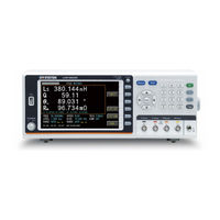
GW Instek LCR Series User Manual (250 pages)
Brand:
GW Instek
| Category:
Measuring Instruments
| Size: 6 MB
Table of Contents
Table of Contents
3
Safety Instructions
5
Etting Started
10
Getting Started
11
LCR-8200 Series Overview
11
Series Lineup
11
Characteristics
12
Accessories
14
Package Contents
15
Appearance
16
Front Panel
16
Rear Panel
18
Set up
19
Tilting the Stand
19
Power up
20
Connect to the Test Terminal
21
Easure (Meter Mode)
23
Measure (Meter Mode)
23
Measure Display Area Description
24
Setting Parameter
25
Setting Frequency
27
Setting Speed
29
Setting Trigger Mode
30
Setting Measurement Level/Alc/Ro
32
Setting DC Bias
34
Setting Measurement AC Range
36
Setting Measurement DC Range
37
Setting Trigger Delay Timer
38
Setting AC/DC Delay Timer
39
Setting Average Count
40
Setting Display VM/IM Mode
41
Setting Beep Mode
42
Setting Statistics Mode
43
Setting Comparator
44
Setting bin Sorting
50
Setting FILE
56
Setting USB Disk
58
Weep (Graph Mode)
60
Sweep (Graph Mode)
60
Sweep Display Area Description
61
Setting Type
62
Setting X-Axis
63
Setting Start
64
Setting Stop
65
Setting Level/Freq
66
Setting Bias
67
Setting Trig
68
Setting Speed
70
Setting Scale
71
Setting Func
72
Setting para
73
Setting Y-Axis
74
Setting Ref
75
Setting Pos
76
Setting DIV/Decade
77
Setting Sweep Delay
78
Setting Output Impedance
79
Setting Keep Previous Trace
80
Setting Trace A/B Color
82
Setting USB Disk
83
Ist (Multi Step Mode)
85
List (Multi Step Mode)
85
[LIST RUN] Page
86
LIST SET/LIST RUN Display Area Description
86
Setting Step
87
Setting Parameter
89
Setting Frequency
91
Setting Level
92
Setting DC Bias
93
Setting Speed
94
Setting Delay
95
Setting Comp Mode
96
Setting Trigger Mode
100
Setting Trigger Delay
103
Setting OUTPUT IMPEDANCE
104
Setting ALC
105
Setting Beep When
106
Setting Range Hold
107
Setting Fail Reset
108
Setting Statistics
109
Setting bin Sorting
110
Setting FILE
116
Setting USB Disk
118
Orrection (Open/Short)
120
Correction (Open/Short)
120
Correction Process
121
Setting Open
123
Setting Short
125
Setting HF Load
127
Setting Spot Load
129
Setting Cable Length
131
Setting Fixture Compensation
132
Setting Spot no
133
Setting Frequency
134
Setting Load Function
135
Setting Reference
137
Measure Load
138
Ystem Configuration
139
System Configuration
139
Setting GPIB Address
140
Setting RS232 BAUD RATE
141
Setting RS232 EOI
142
Setting LAN PORT
143
Setting HANDLER INTERFACE
145
Setting KEY BEEP
146
Emote Control
147
Remote Control
147
Handler Overview
148
Terminal Type
148
Terminal Diagrams
149
Universal Terminal
150
Meter Mode (bin Off) Terminal
151
List Mode (bin Off) Terminal
151
Meter/List Mode (bin On) Terminal
152
Electrical Parameters
153
Timing Chart
156
Configure Interface
157
GPIB Interface
157
Configure GPIB Interface
158
LAN Interface
158
RS-232C Interface
159
Configure RS232 Interface
159
USB Interface
160
Configure USB Interface
160
Install USB Driver
161
External Trigger Input
163
Ommand Overview
164
Command Overview
164
Command Syntax
165
Command Error Code
168
Command List Command
169
Command List
169
Commands
170
Status:operation:condition
176
Status:operation:event
176
Status:operation:enable <NR1
176
Status:operation:enable
176
Status:questionable:condition
176
Status:questionable:event
177
Status:questionable:enable <NR1
177
Status:questionable:enable
177
Cls
177
Ese <Nr1
177
Ese
177
Esr
178
Idn
178
Opc
178
Opt
178
Rst
179
Sre <Nr1
179
Sre
179
Stb
179
Wai
179
Tst
180
Trg
180
Trigger
180
Display:page{Measure|Sweep|Correction|Lset|Lrun|Lcorrection| System
180
Display:page
180
Measure Subsystem
181
Measure:parameter
181
Off|Rdc|Ls|Lp|Cs|Cp|Q|D|Rs|Rp|Z|Deg|Rad|R|X|Y|G|B|E|U
181
Measure : Frequency < Frequency Nr3/Disc
181
Measure:frequency
181
Measure:speed
182
Measure:beeper {OFF|PASS|OK|FAIL|NG|0|1|2]
182
Measure:beeper
182
Measure:voltage:ac <Voltage Nr3/Disc
182
Measure:voltage:ac
182
Measure:current:ac <Current Nr3/Disc
183
Measure:current:ac
183
Measure:alc {OFF|ON|0|1
184
Measure:alc
184
Measure:smonitor {0|1|OFF |ON
184
Measure:smonitor
184
Fetch:smonitor:DC
184
Fetch:smonitor:ac
184
Measure:average <Average NR1
185
Measure:average
185
Measure:font {Small|Large
185
Measure:font
185
Measure:trigger:delay <Delay Time Nr3/Disc
185
Measure:trigger:delay
185
Measure:delay <Delay Time Nr3/Disc
186
Measure:delay
186
Measure:trigger:mode {Repeat|0|Single|1
186
Measure:range:DC {1|2|3|4|AUTO|HOLD
186
Measure:range:DC
186
Measure:range:ac {1|2|3|4|AUTO|HOLD
187
Measure:oimpedance {100|25
187
Measure:oimpedance
187
Measure:comparator:parameter {1|2|3|4
187
Measure:comparator:parameter
187
Measure:comparator:state {OFF|ON|0|1
188
Measure:comparator:state
188
Measure:comparator:mode <Absolute|Deviation|Percent|0|1|2>188
188
Measure:comparator:nominal <Nominal Value NR3
188
Measure:comparator:nominal
188
Measure:comparator:upper <Upper Limit NR3
189
Measure:comparator:upper
189
Measure:comparator:lower <LOWER Limit NR3
189
Measure:comparator:display
189
Measure:bin:parameter
190
Off|Rdc|Ls|Lp|Cs|Cp|Q|D|Rs|Rp|Z|Deg|Rad|R|X|Y|G|B|E|U
190
Measure:bin:number {2|3|4|5|6|7|8|9|Maxium|Minimum
190
Measure:bin:number
190
Measure:bin:method
190
Equal|Sequential|Tolerance|Random|0|1|2|3
190
Measure:bin:mode <Absolute|Deviation|Percent|0|1|2
191
Measure:bin:mode
191
Measure:bin:nominal <Nominal Value NR3
191
Measure:bin:nominal
191
Measure:bin:limit <Nominal Value NR3
191
Measure:bin:limit
191
Measure:file:load <Filename
191
Measure:fil E:LOAD
192
Fetch
192
Correction:open
193
Correction:short
194
Correction:open:state {OFF|ON|0|1
194
Correction:open:state
194
Correction:short:state {OFF|ON|0|1
194
Correction:short:state
194
Correction:cable {0|0.5|1|2
194
Correction:cable
194
LIST Subsystem
195
List:step{1|2|3|4
195
List:step
195
List:parameter
195
Off|Rdc|Ls|Lp|Cs|Cp|Q|D|Rs|Rp|Z|Deg|Rad|R|X|Y|G|B
195
List:frequency <Frequencynr3/Disc
195
List:frequency
195
List:voltage<Voltage Nr3/Disc
196
List:voltage
196
List:current <Current Nr3/Disc
196
List:current
196
List:speed {Maximum|Fast|Medium|Slow|Slow2|0|1|2|3|4
197
List:speed
197
List:delay <Delay Time Nr3/Disc
197
List:delay
197
List:comparator:mode <Absolute|Deviation|Percent|0|1|2
198
List:comparator:nominal <Nominal Value NR3
198
List:comparator:nominal
198
List:comparator:upper <Upper Limit NR3
198
List:comparator:upper
198
List:comparator:lower <LOWER Limit NR3
199
List:comparator:lower
199
List:bin:parameter
199
Off|Rdc|Ls|Lp|Cs|Cp|Q|D|Rs|Rp|Z|Deg|Rad|R|X|Y|G|B
199
List:bin:number {2|3|4|5|6|7|8|9|Maxium|Minimum
199
List:bin:number
199
List:bin:method
200
LIST:BIN:MODE <Absolute|Deviation|Percent|0|1|2
200
List:bin:mode
200
List:bin:nominal <Nominal Value NR3
200
List:bin:nominal
200
List:bin:limit <Nominal Value NR3
201
List:bin:limit
201
List:trigger:mode {Repeat|Single|Auto
201
List:trigger:mode
201
List:trigger:delay <Delay Time Nr3/Disc
201
List:trigger:delay
201
List:oimpedance {100|25
202
List:oimpedance
202
List:alc {Off|On|0|1
202
List:beeper {OFF|PASS|OK|FAIL|NG|0|1|2]
202
List:beeper
202
List:range {AUTO|HOLD|0|1
202
List:range
202
List:retest {OFF|STEP|ALL|0|1|2
203
List:retest
203
List:upload {0|1
203
List:upload
203
Lcorrection:open
203
Lcorrection:short
204
Lcorrection:open:state {OFF|ON|0|1
204
Lcorrection:open:state
204
Lcorrection:short:state {OFF|ON|0|1
204
Lcorrection:short:state
204
Lcorrection:cable {0|0.75|1|2
205
Lcorrection:cable
205
LIST:FILE:LOAD <Filename
205
List:file:load
205
Sweep Subsystem
206
Sweep:type {Frequency|Vac|Iac
206
Sweep:type
206
Sweep:xaxis {Logarithm|Linear
206
Sweep:xaxis
206
Sweep:xaxis:data
206
Sweep:start <Startnr3/Disc
207
Sweep:start
207
Sweep:stop <Stopnr3/Disc
207
Sweep:stop
207
Sweep:frequency <Frequencynr3/Disc
208
Sweep:frequency
208
Sweep:voltage <Voltage Nr3/Disc
209
Sweep:voltage
209
Sweep:current <Currentnr3/Disc
209
Sweep:current
209
Sweep:trigger:mode <Repeat|Single|0|1
210
Sweep:trigger:mode
210
Sweep:speed {Fast|Medium|Slow|1|2|3
210
Sweep:speed
210
Sweep:trace {A|B
211
Sweep:trace
211
Sweep:function
211
Ls|Lp|Cs|Cp|Q|D|Rs|Rp|Z|Deg|Rad|R|X|Y|G|B,Off|Ls|Lp|Cs|Cp|Q|D|Rs |Rp|Z|Deg|Rad|R|X|Y|G|B
211
Sweep:analysis:model {A|B|C|D|E|F|G|OFF
211
Sweep:analysis:model
211
Sweep:delay <Delay Timenr3/Disc
212
Sweep:delay
212
Sweep:oimpedance {100|25
212
Sweep:oimpedance
212
Sweep:keep {OFF|ON|0|1
212
Sweep:keep
212
Sweep:traca:parameter
213
Ls|Lp|Cs|Cp|Q|D|Rs|Rp|Z|Deg|Rad|R|X|Y|G|B
213
Sweep:traca:yaxis {Logarithm|Linear
213
Sweep:traca:yaxis
213
Sweep:traca:reference <Value NR3
213
Sweep:traca:reference
213
Sweep:traca:position {-10 ~ 16|Maximun|Minimum
214
Sweep:traca:position
214
Sweep:traca:division <Value Nr3/Disc
214
Sweep:traca:division
214
Sweep:traca:decade {1~12
214
Sweep:traca:decade
214
Sweep:traca:maximun
215
Sweep:traca:minimum
215
Sweep:traca:result
215
Sweep:tracb:parameter
215
Ls|Lp|Cs|Cp|Q|D|Rs|Rp|Z|Deg|Rad|R|X|Y|G|B
215
Sweep:traca:parameter
215
Sweep:tracb:yaxis {Logarithm|Linear
216
Sweep:tracb:yaxis
216
Sweep:tracb:reference <Value NR3
216
Sweep:tracb:reference
216
Sweep:tracb:position {-10 ~ 16|Maximun|Minimum
216
Sweep:tracb:position
216
Sweep:tracb:division <Value Nr3/Disc
217
Sweep:tracb:division
217
Sweep:tracb:decade {1~12
217
Sweep:tracb:decade
217
Sweep:tracb:maximun
217
Sweep:tracb:minimum
218
Sweep:tracb:result
218
Sweep:autoscale
218
Sweep:result
218
Sweep:analysis:result
219
Sweep:analysis:calculate
219
Sweep:srf:series
219
Sweep:srf:parallel
219
Ppendix
220
Appendix
220
Preset
221
Specifications
223
General Specifications
223
Specifications
224
Dimensions
230
Declaration of Conformity
231
Measurement Basics
232
Resistance (R) and Conductance (G)
233
Capacitance (C)
235
Inductance (L)
236
Reactance (X) and Susceptance (B)
237
Impedance (Z) and Admittance (Y)
239
Quality Factor (Q) and Dissipation Factor (D)
241
Phase Angle (Θ)
243
Overall Impedance Measurement Theory
244
Characteristics Example
248
High and Low Impedance Criteria
250
Advertisement
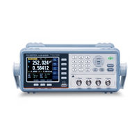
GW Instek LCR Series User Manual (143 pages)
Brand:
GW Instek
| Category:
Measuring Instruments
| Size: 3 MB
Table of Contents
Table of Contents
5
1 Unpacking and Preperation
15
Incoming Inspection
15
Environmental Requirements
16
Cleaning
16
How to Remove the Handle
17
Figure 1 -1 How to Remove the Handle
17
2 Overview
18
Introduction
18
Main Specifications and Features
19
Test Function
19
Equivalent Circuit
19
Ranging
19
Measurement Speed
19
Table 2-1 Equivalent Circuit
19
Trigger Mode
20
Basic Accuracy
20
Display Range
20
Test Signal
20
Test Signal Frequency
20
Table 2-2 Display Range
20
Test Signal Level
21
Output Impedance
21
Main Functions
21
Correction Function
21
Comparator Function (Sorting)
21
List Sweep
22
Measurement Assistance Functions
22
Files
22
Key Lock
22
Options
22
USB Host Port
22
Figure 2 -1 Disk Ready
23
Figure 2 -2 Screen Saved
23
DC Bias Voltage
24
3 Startup
25
Front Panel
25
Figure 3 -1 Front Panel
25
Table 3-1 Front Panel Description
25
Rear Panel
26
Power On/Off
26
Power on
26
Power off
26
Figure 3 -2 Rear Panel
26
Table 3-2 Rear Panel Description
26
Warm-Up Time
27
Connect to the Device under Test (DUT)
27
Figure 3 -3 Connect to DUT
27
4 Measure Key
28
MEAS DISPLAY] Page
28
Measurement Function [FUNC]
29
Figure 4 -1 [MEAS DISPLAY] Page
29
Table 4-1 Measurement Parameter Combinations
29
Table 4-2 Monitor Parameters
29
Table 4-3 Measurement and Monitor Parameter Descriptions
30
Impedance Range [RANGE]
31
Table 4-4 Impedance Range Mode
31
Table 4-5 Effective Measurement Range for the Impedance Range When in HOLD State
32
Table 4-6 DCR FUNC Effective Measurement Range for the Impedance Range When in HOLD State
32
Test Frequency [FREQ]
33
Table 4-7 Frequency Range and Resolution
33
Table 4-8 LCR-6300'S Predefined Test Frequencies that Can be Selected by Using INCR+/DECR
34
Table 4-9 LCR-6200'S Predefined Test Frequencies that Can be Selected by Using INCR+/DECR
34
Table 4-10 LCR-6100'S Predefined Test Frequencies that Can be Selected by Using INCR+/DECR
34
Table 4-11 LCR-6020'S Predefined Test Frequencies that Can be Selected by Using INCR+/DECR
34
Trigger Mode [TRIG]
35
Table 4-12 LCR-6002'S Predefined Test Frequencies that Can be Selected by Using INCR+/DECR
35
Test Signal Voltage/Current Level [LEVEL]
36
Table 4-13 Test Voltage/Current Level that Can be Selected with
36
Measurement Speed [SPEED]
37
Measurement Log [LOG]
38
OPEN/SHORT] Page
40
Open Correction [OPEN]
41
Figure 4 -2 [OPEN/SHORT] Page
41
Figure 4 -3 Stray Admittance
41
Short Correction [SHORT]
42
Figure 4 -4 Residual Impedances
42
SPOT Correction
43
LIST SETUP] Page
45
Measurement Function [FUNC]
46
Test Mode [MODE]
46
Figure 4 -5 [LIST SETUP] Page
46
List Measurement Parameters
47
List Point and Limit Modes
48
LIST MEAS] Page
49
Trigger Mode [TRIG]
49
Figure 4 -6 [LIST MEAS] Page
49
Test Mode [MODE]
50
Range Mode [RANGE]
51
Measurement Log [LOG]
51
ENLARGE DISPLAY] Page
53
Enlarge Display
53
Direct Comparison Function
54
Figure 4 -7 [ENLARGE DISPLAY] Page
54
Figure 4 -8 Direct Comparison Setting
54
5 Setup Key
55
MEAS SETUP] Page
55
Figure 5 -1 [MEAS SETUP] Page
55
Source Output Impedance [SRC RES]
56
Averaging Factor [AVG]
57
DC Bias Voltage [BIAS]
57
Auto LCZ Function [AUTO LCZ]
58
Monitor 1 and Monitor 2 [MON 1][MON 2]
58
Auto Level Control [Alc]
59
Measurement Delay [DELAY]
59
Nominal Value [NOMINAL]
60
BIN SETUP] Page
61
Measurement Function [FUNC]
62
Comparator Function ON/OFF
62
Figure 5 -2 [BIN SETUP] Page
62
Figure 5 -3 Page Comparator Workflow
63
Auxiliary bin [AUX]
64
Primary Parameter Comparator Limit Mode [MODE]
64
Figure 5 -4 Absolute Mode
65
Figure 5 -5 Percentage Mode
65
Figure 5 -6 Sequential Mode
66
Nominal Value for Tolerance Mode
67
Beep Feature
67
Total Number of Bins [#-BINS]
67
Lower and Upper Limits
68
BIN MEAS] Page
68
Comparator Function ON/OFF
69
Figure 5 -7 [BIN MEAS] Page
69
Auxiliary bin [AUX]
70
BIN COUNT] Page
70
Figure 5 -8 [BIN COUNT] Page
70
Counter Function [COUNT]
71
6 System Configurations
72
SYSTEM CONFIG] Page
72
Setting the System Date and Time
73
Figure 6 -1 [SYSTEM CONFIG] Page
73
Account Setting
74
KEY BEEP Setting
75
Baud Rate
75
Terminator
76
Hand Shake
76
Error Code
77
Result
78
Data Buffer
78
Default Set
79
SYSTEM INFO] Page
80
Figure 6 -2 [SYSTEM INFO] Page
80
7 File Operation
81
FILE] Page
81
Figure 7 -1 [FILE] Page
81
Media]
82
Recall a File at Startup [AUTO RECALL]
82
Auto Save Data to Last File [AUTO SAVE]
83
File Operation
83
8 Handler Interface
84
Pin Assignment
85
Figure 8 -1 Pin Assignment
85
Table 8-1 Handler Interface Signals ~ Output Pins
85
Table 8-2 Handler Interface Signals ~ Input Pins
86
Table 8-3 Handler Interface Signals ~ Power Pins
86
Connection
87
Figure 8 -2 Circuit of Input Pins
87
Timing Chart for Handler Interface
88
Figure 8 -3 Circuit of Output Pins (bin Sorting, Index, EOM)
88
Figure 8 -4 Timing Chart
88
Table 8-4 Timing Definitions
88
9 Examples
89
Basic Measurement Procedure
89
Example
90
Figure 9 -1 Basic Measurement Procedure
90
Figure 9 -2 Measurement Results
93
10 Remote Control
94
About RS-232C
94
Figure 1 0-1 the RS-232 Connector on the Real Panel
94
To Select Baud Rate
95
Figure 1 0-2 PC - LCR-6000 Series Connection Uses a Null Modem Connection
95
SCPI Language
96
11 Command Reference
97
Terminator
97
Notation Conventions and Definitions
97
Command Structure
97
Figure 1 1-1 Command Tree Example
98
Header and Parameters
100
Table 11-1 Multiplier Mnemonics
100
Command Reference
101
Display Subsystem
102
Disp:line
102
Disp:page
102
Figure 1 1-2 Command Tree Example
102
Function Subsystem
104
Function
104
Figure 1 1-3 Function Subsystem Tree
104
Function:impedance:auto
105
Function:impedance:range
105
Function:dcr:range
105
Function:range:auto
106
Function:monitor 1 /2
106
Figure 1 1-4 FREQ Subsystem Command Tree
107
Level Subsystem
108
Level:voltage (=Voltage[:Level])
108
Figure 1 1-5 Level Subsystem Command Tree
108
Level:current (=Current[:Level])
109
Level:sresistance (= Voltage:sresistance)
109
Level:alc (=Amplitude:alc)
110
Level:mode
110
Aperture Subsystem
111
Aperture:rate
111
Aperture:avg
111
Fetch Subsystem
112
Fetch
112
Fetch:impedance
113
Fetch:main
113
Fetch:monitor1? /2
113
Fetch:monitor
113
Fetch:list
114
Comparator Subsystem
115
Comparator:state
115
Comparator:mode
116
Comparator:aux
116
Comparator:bins
116
Comparator:tolerance:nominal
117
Comparator:tolerance:bin
117
Comparator:slim
117
Comparator:beep
118
Comparator:open
118
LIST Subsystem
119
List:parameter
119
List:stat
119
List:band
120
Correction Subsystem
121
Correction:open
121
Correction:open:state
122
Correction:open:lcr
122
Correction:open:dcr
122
Correction:short
122
Correction:short:state
123
Correction:short:lcr
123
Correction:short:dcr
123
Correction:spot:state
123
Correction:spot:frequency
124
Correction:spot:open
124
Correction:spot:short
124
Trigger Subsystem
125
Trigger[:Immediate]
125
Trigger:source
125
Trigger:delay
125
BIAS Subsystem
126
FILE Subsystem
127
File
127
File:save
127
File:load
127
File:delete
128
Error Subsystem
128
Error
128
SYSTEM Subsystem
128
System:shakehand
128
System:code
128
System:keylock
129
System:result
129
Common Commands
129
Idn
129
Trg
129
Sav
130
Rcl
130
12 Specification
131
General Specification
131
Dimensions
135
13 Accuracy
136
Accuracy
137
L, C, R |Z| Measurement Accuracy
137
Accuracy for D
137
Accuracy for Q
138
Accuracy for
138
Accuracy for Rp
138
Accuracy for Rs
139
Correction Factors that Affect Measurement Accuracy
139
Table 13-1 Impedance Correction Factors
141
Table 13-2 Temperature Correction Factor K
142
Table 13-3 Correction Factor for Interpolated Open/Short Trimming K Table 13-4 Correction Factors for the Cable Length of Test Leads K L
142
Declaration of Conformity
143
Advertisement
Related Products
GW Instek LCR-6300
GW Instek LCR-6002
GW Instek LCR-6100
GW Instek LCR-8101
GW Instek LCR-827
GW Instek LCR-800 Series
GW Instek LCR-8101G
GW Instek LCR-8210
GW Instek LCR-8220
GW Instek LCR-6000 Series
GW Instek Categories
Power Supply
Test Equipment
Measuring Instruments
Multimeter
Inverter
More GW Instek Manuals
Login
Sign In
OR
Sign in with Facebook
Sign in with Google
Upload manual
Upload from disk
Upload from URL