Table of Contents
Advertisement
Gate Swings Evenly and Freely
Post Bracket
Hung Firmly and Plumb
Secondary Opener
Power Cable
Fence Post Set in Concrete
This product meets the requirements of UL325, the standard for gate operator safety.
Mighty Mule
is the retail brand of Nortek Security and Control, LLC.
®
Copyright
©
2019 Nortek Security and Control, LLC.
Installation Manual
(For a single or dual gate installation)
Warning Sign
Gate Bracket
Horizontal Support
Horizontal Support
PVC conduit (not included)
to run second opener power
cable under driveway.
Dual gate installation MM572W]
Example of Dual Gate finished installation
(Installations vary slightly on different types of gates)
MM571W
MM572W
Single gate installation [MM571W]
Warning Sign
Primary Gate Opener
Gate Bracket
Fence Post Set in Concrete
PVC conduit (not included)
to protect wire from lawn
mowers and weed eaters.
Post Bracket
Control Box
120 Volt indoor
Transformer
(surge protector
not supplied)
Run 1000' (max.) of low voltage
wire to control box from
transformer (wire not included).
10022116 A
Advertisement
Table of Contents
Troubleshooting

Subscribe to Our Youtube Channel
Related Manuals for Mighty Mule MM571W


Summary of Contents for Mighty Mule MM571W
- Page 1 MM571W MM572W Installation Manual (For a single or dual gate installation) Single gate installation [MM571W] Gate Swings Evenly and Freely Post Bracket Post Bracket Control Box Hung Firmly and Plumb Warning Sign Warning Sign 120 Volt indoor Primary Gate Opener...
- Page 2 Product Usage The Mighty Mule Gate Operator meets all of the safety requirements of a Class I Residential Vehicular Gate Operator and is intended for use solely with vehicular swing gates in single-family residential applications that meet the Class I category listed in the table below.
-
Page 3: Table Of Contents
Before You Begin ........................... xi Check Existing Gate Size and Material ............................xii IMPORTANT: Check for Proper Gate Installation ..........................xii Items Included for Primary Gate Opener Installation (MM571W) ......................xiii Items Included for Secondary Opener Installation (MM572W) ......................xiii Tools Needed ....................................xiv Items Not Included ..................................xiv... -
Page 4: Please Read This First
When correctly installed and properly used, position, it can be set to remain open up to 120 seconds your Mighty Mule Gate Operator will give you many years before automatically closing. Pressing the transmitter of reliable service. Please read the following information... - Page 5 Because Mighty Mule automatic gate operators are only part of the total gate operating system, it is the responsibility of the installer and end user to ensure that the total system is safe for its intended use.
-
Page 6: Important Safety Information
ZONE 1 ZONE 2 ZONE 2 ZONE 5 ZONE 5 ZONE 3 ZONE 3 Driveway ZONE 4 ZONE 4 Entrapment Zones for a Pull-To-Open Application Gate in the Gate in the MM572W Open Position Open Position MM571W / MM572W Installation Instructions... - Page 7 5. Secure outdoor or easily accessed gate operator controls in order to prohibit unauthorized use of the gate. Pull-To-Open Application Pull-To-Open MM572W Application Moving Gate Moving Gate Area Area Driveway NEVER INSTALL any control device within the indicated area Pull-To-Open Application MM571W / MM572W Installation Instructions...
- Page 8 Contact Nortek Security and Control for free Should you need a replacement manual, a copy can replacements. be obtained by downloading one from the Mighty Mule web site (www.mightymule.com), by contacting Nortek 2. The gate is automatic and could move at any time, Security and Control by calling 1-800-543-4283 and posing serious risk of entrapment.
- Page 9 Entrapment Alarm The Mighty Mule Automatic Gate Operator is designed to stop and reverse the gate when the gate comes in contact with an obstruction. Additionally, these operators are equipped with an audio entrapment alarm which will activate if the unit obstructs twice while opening or closing.
-
Page 10: Installing Warning Signs And Pedestrian Gates
INSTALLING WARNING SIGNS AND PEDESTRIAN GATES Warning signs alert people of automatic gate operation and are required when installing Mighty Mule Automatic Gate Operators. A minimum of two WARNING SIGNS must be installed in the area of the gate. Each sign is to be visible by persons located on the side of the gate on which the placard is installed. -
Page 11: Required Safety Precautions For Gates
Voltage: 12 Vdc; Frequency: 0 Hz; Power: 25 W E472888 Class I Vehicular Gate Nortek Security & Control – Carlsbad, CA USA 10019665A Product identi cation label (1) installed on the side of the Control box. MM571W / MM572W Installation Instructions... -
Page 12: Technical Specifications
The system is powered by a 12 Vdc battery (included). Optional automotive or marine battery may be used (not included). • Battery charge is maintained by Mighty Mule transformer or optional Mighty Mule Solar Panels. • The system uses 25 A Mini ATC blade-style fuses. -
Page 13: Powering Options
[FM123]. Refer to the Solar Panel and Gate Activity chart below. ● All low voltage wire used with the Mighty Mule gate operator must be 16 gauge dual conductor, stranded, direct burial wire [RB509]. Do not run more than 1000 ft. of wire. -
Page 14: Check Existing Gate Size And Material
2 ft. or Less from post protects against lightning strikes. If installed correctly, a grounding system will help minimize damage to your gate Copper ground 2 Inches or rod clamp Less above operator. ground 12awg or Larger Ground MM571W / MM572W Installation Instructions... -
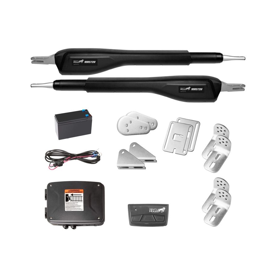
Page 15: Items Included For Primary Gate Opener Installation (Mm571W)
ITEMS INCLUDED FOR PRIMARY GATE OPENER INSTALLATION (MM571W) Transformer Operator Closed Position Stop Plate Literature kit with gate warning signs Gate Bracket Battery Box, Control Box, Antenna, Battery & Battery Harness Transmitter Post Brackets (2) Post Pivot Bracket 8” Nylon Cable Tie (10) 3/8”... -
Page 16: Tools Needed
See the Reinforcing Gates for the Gate Brackets examples, next page. CHECK DIRECTION OF GATE SWING (Requires Push-To-Open Bracket #FM148—NOT INCLUDED) Your Property Your Property Pull-to-Open Option Push-to-Open Option Instructions begin on page 2. Instructions begin on page 8. MM571W / MM572W Installation Instructions... -
Page 17: Mechanical Installation
(not supplied) Thin Walled Tube Gate Muffler Clamp for Gate Bracket Gate Bracket Gate Bracket Wood or Metal Panel Reinforcement Gate (not supplied) 1" x 6" Wood Reinforcement Wood or Metal Reinforcement 1” x 6” Reinforcement MM571W / MM572W Installation Instructions... -
Page 18: Pull-To-Open Operator Mounting ( Most Common )
PULL-TO-OPEN OPERATOR MOUNTING ( MOST COMMON ) Your Property Step 1 ● Assemble the gate post bracket sub assembly as displayed. Step 2 ● Attach the gate post bracket subassembly and gate bracket to the operator as shown. MM571W / MM572W Installation Instructions... - Page 19 20 inches. ● Make adjustments to the mounting brackets to achieve the recommended clearances. Open TIP: Turning the pivot bracket over gives more hole alignment options Position for the gate post pivot bracket assembly. MM571W / MM572W Installation Instructions...
- Page 20 ● Mark the center of the mounting locations for the gate bracket. Step 7 ● Remove the gate post and gate brackets. ● Use a hammer and center punch to mark the center of the mounting locations. MM571W / MM572W Installation Instructions...
- Page 21 Note: Some installations may require additional reinforcement be installed on the gate. Step 9 ● Secure the gate post bracket subassembly with the supplied hardware as shown. MM571W / MM572W Installation Instructions...
- Page 22 See front page of this manual for a complete installation example. After you have mounted the second operator, proceed to Installation of the Closed Position Stop Plate on the following pages. MM571W / MM572W Installation Instructions...
-
Page 23: Installing The Closed Position Stop Plate / Pull-To-Open
Note: For MM572W installations, the closed position stop plate should be installed on the leading edge of the PRIMARY gate leaf, and adjusted to close against the leading edge of the SECONDARY gate leaf. MM571W / MM572W Installation Instructions... -
Page 24: Push-To-Open Operator Mounting
Push-to-Open pivot bracket (FM148). Must be purchased separate. Push-to-Open pivot 11” bracket (FM148) Step 2 ● Attach the gate post bracket subassembly and gate bracket to the operator as shown. 11” MM571W / MM572W Installation Instructions... - Page 25 20 inches. 20” MAX ● Make adjustments to the mounting brackets to achieve the recommended clearances. TIP: Turning the pivot bracket over gives more hole alignment options for the gate post pivot bracket assembly. MM571W / MM572W Installation Instructions...
- Page 26 ● Mark the center of the mounting locations for the gate bracket. Step 7 ● Remove the gate post and gate brackets. ● Use a hammer and center punch to mark the center of the mounting locations. MM571W / MM572W Installation Instructions...
- Page 27 Note: Some installations may require additional reinforcement be installed on the gate. Step 9 ● Secure the gate post bracket subassembly with the supplied hardware as shown. MM571W / MM572W Installation Instructions...
- Page 28 ● Ensure the operator arm is level, adjusting the post bracket location if necessary. ● Once level, ensure all hardware is tight. ● Remove excess bolt length with a hacksaw. MM571W / MM572W Installation Instructions...
-
Page 29: Installing The Closed Position Stop Plate / Push-To-Open
Note: For MM572W installations, the closed position stop plate should be installed on the leading edge of the PRIMARY gate leaf, and adjusted to close against the leading edge of the SECONDARY gate leaf. MM571W / MM572W Installation Instructions... -
Page 30: Control Box Installation
● Place the battery into the right side of the battery box with the terminals facing to the right and towards the top of the battery box. ● Route the battery harness as shown. MM571W / MM572W Installation Instructions... - Page 31 The cover will be attached on hinges. Feed battery cables through access hole Step 6 Attenna ● Install the Antenna by screwing it in place on the Cable SMA connector. ● Orient the antenna to the sky, and securely tighten. MM571W / MM572W Installation Instructions...
-
Page 32: Connecting The Operator(S) And Battery
● Insert the wire harness through the cable gland into the control box at least 3” to allow connection to the operator wiring terminals. LOCK ● Secure the cable in place by tightening the sealing nut. SECURE SEALING NUT MM571W / MM572W Installation Instructions... -
Page 33: Connecting The Operator(S) And Battery
Step 4 TERM6 BAT+ BAT– 1 2 3 4 5 RESET AUTO CLOSE TERM6 ● Connect the battery power wires: BAT+ Red to Red (BAT+) and Black to BAT– Black (BAT–). LOCK Battery Power Access MM571W / MM572W Installation Instructions... -
Page 34: Transformer Or Solar Panel Wiring Installation
● Along the identified path between outlet and control box, dig a trench to lay the low voltage transformer wire (RB509 sold separately). ● Use PVC conduit from the ground up to the control box. MM571W / MM572W Installation Instructions... -
Page 35: Transformer Or Solar Panel Wiring Installation
Second opener to the control box. The buried conduit will protect the 32 foot power cable from automobile tires, lawn mower blades, weed eaters, and grazing animals. ● Pull the secondary operator cable through the conduit. ● Repeat steps 1-3 above for connecting the SECONDARY operator cable to the control board. MM571W / MM572W Installation Instructions... - Page 36 Note: Use of a surge protector is strongly recommended. ry Power Access MM572 Installation - For dual arm installation, drill through one of the Alternate Access slots to install the Transformer or Solar power wires. MM571W / MM572W Installation Instructions...
-
Page 37: Electrical Installation And Setup
● Locate the ON/OFF switch on the bottom left of the control box. ● Toggle the switch to the ON position. ● The system will take approximately 20 seconds to power up indicated by an audible tone and LED D17 will flash. LOCK MM571W / MM572W Installation Instructions... -
Page 38: Transmitter Programming
2. Press and hold the (down arrow) button until LED1, 2 & 3 flash and the buzzer sounds. (Approximately 10 seconds.) Note: The control board can store a total of 50 transmitter and/or keypad codes. The system is compatible with Mighty Mule DIP switch transmitters and keypads. -
Page 39: Operator Limit Setting
OPERATOR LIMIT SETTING Setting the Operator's Extended Limit (MM571W Only): 1. Press and hold the (up arrow) and (return/enter) buttons until LED1 turns on and the buzzer sounds. Release. 2. Use the (up arrow) and (down arrow) buttons to jog the gate operator to the EXTENDED position. -
Page 40: Auto Close Setting
This product has the ability of being control via a smart device (i.e. smartphone) with the addition of the MMS100 smart kit. Refer to the instructions contained in the MMS100 kit or visit www.mightymule.com for more information MM571W / MM572W Installation Instructions... -
Page 41: Connecting Additional Devices
Connecting Additional Devices Mighty Mule strongly recommends the use of additional obstruction detection devices however we do not endorse any specific brand names. Only use products that are listed to be in compliance with any applicable UL safety standards and national and regional codes. -
Page 42: Control Board Connections
See page 27 of this manual for connection diagram. The LOCK Relay should only be used for switching LOCK V-. NOTE: DO NOT connect positive voltage to the AUX or LOCK Relays. MM571W / MM572W Installation Instructions... -
Page 43: Connecting Accessories
NOTE: Connections are for typical applications. information if needed. For additional connection options not illustrated here refer to the accessory manual for details. For FM130/FM130-SW and FM136, see Appendix A in this manual. MM571W / MM572W Installation Instructions... -
Page 44: Maintenance
● Monthly, turn off the power switch and disconnect the Mighty Mule and move the gate to make sure the gate is moving freely without sticking or binding. Lubricate the hinges or repair the gate as required before reattaching the Mighty Mule. -
Page 45: Troubleshooting Guide - Audible Feedback
Arm rev. counter stuck switch h Arm power cable wires shorted, crossed or cut/disconnected Stuck limit switch Secondary arm or 6 beeps, pause, 6 beeps Reading open motor circuit h Arm rev. counter stuck switch MM571W / MM572W Installation Instructions... - Page 46 Internal arm problem/board The unit clicks with no arm h Internal arm problem Open motor circuit movement Additional information can be found by contacting Nortek Security and Control. MM571W / MM572W Installation Instructions...
-
Page 47: Troubleshooting Guide - Visual Feedback
Ensure transformer or solar panel wires are properly connected to the control board. It is necessary to observe correct polarity. Connect battery/batteries Charge LED Flashing Battery or Batteries disconnected MM571W / MM572W Installation Instructions... - Page 48 Check battery connections and harness, ensure the battery is incorrectly connected red to red (+) and black to black (-) h Replace harness fuse and F2 fuse if blown Additional information can be found by contacting Nortek Security and Control. MM571W / MM572W Installation Instructions...
-
Page 49: For Your Records
Refer to this information when calling Nortek Security and Control for service or assistance with your automatic gate operator. Serial Number ____________________________________________ Date of Purchase _________________________________________ Place of Purchase ________________________________________ Remember to keep all receipts for proof of purchase. MM571W / MM572W Installation Instructions... -
Page 50: Repair Service
Repair Service If your Mighty Mule Gate Opener is not operating properly, please follow the steps below: 4. If repair or replacement of your gate operator is necessary, 1. First use the procedures found in the Maintenance & the Service Department will assign a Return Authorization... -
Page 51: Accessories
(sold separately). Pin Lock (FM133) The Pin Lock substitutes for the clevis pin at the front end of the Mighty Mule gate operators. Helps prevent theft of the operator from the gate, while allowing quick release of the operator. - Page 52 Mighty Mule¨, E-Z Gate¨, Nortek Security and Control¨, “Dual Sense Technology” are registered trademarks of Nortek Security and Control, LLC, America’s DIY Automatic Gate Openers is a trademark of Nortek Security and Control, LLC and are the exclusive property of Nortek Security and Control, LLC (“Nortek Security and Control”).
-
Page 53: Accessory Installation Instructions
FM136 per the accessory instructions. Notes: 1. If you need to erase this device, repeat steps 2-3 above. 2. Erasing all transmitters on the gate operator control board will erase this device. MM571W / MM572W Installation Instructions... -
Page 54: Gate Operator Installation Checklist
10. Reviewed all safety instructions, and keep the safety instructions and owner’s information sheets for ❑ reference. 11. Review and understand the maintenance schedule for both the gate and the gate operator. ❑ MM571W / MM572W Installation Instructions... - Page 55 Telephone Mighty Mule Sales: 1-800-543-4283 • Fax (850) 575-8912 or Mighty Mule Technical Service: 1-800-543-1236 • Fax (850)575-8950 www.mightymule.com Copyright © 2019 Nortek Security and Control, LLC. MM571W / MM572W Installation Instructions...
- Page 56 MM571W / MM572W Installation Instructions...
Need help?
Do you have a question about the MM571W and is the answer not in the manual?
Questions and answers
The Mule gate was opened. When the remote was pressed to close, there was one very long beep and the gate did not close and the system appeared to just shut down.
A long beep when trying to close the Mighty Mule MM571W gate indicates that the control board senses a continuous alarm due to an obstruction or a lack of arm movement. The system shuts down because it detects that the gate requires maintenance or is too difficult to move. To resolve this, check the gate for level and plumb, ensure it moves freely without sticking or binding, and adjust the force factor if necessary.
This answer is automatically generated
Setting open limit, gate traveling too far when opening. MM572
To set the open limit for the Mighty Mule MM571W gate opener:
1. Press and hold the (up arrow) and (return/enter) buttons until LED1 turns on and the buzzer sounds, then release.
2. Use the (up arrow) and (down arrow) buttons to move the PRIMARY operator to the desired OPEN position.
3. Press and release the (return/enter) button to set the OPEN limit.
This answer is automatically generated