Table of Contents
Advertisement
Receiver
120 Volt indoor
Transformer
(surge protector
not supplied)
Run 1000' (max.) of low
voltage wire to control
box from transformer
(wire not included).
This product meets the requirements of UL325 6th Edition, 2016, the standard for gate
operator safety.
For 24 hour/day, 7 day/week Technical Service visit http://support.gtoinc.com
For more information on Mighty Mule's full line of Automatic Gate Operators and Access Controls visit
Mighty Mule® is the retail brand of GTO Access Systems, LLC
Printed in China for GTO Access Systems, LLC.
Installation Manual
Gate Swings Evenly and Freely
Hung Firmly and Plumb
Post Bracket Assembly
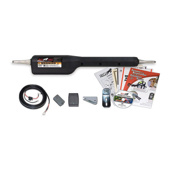
Single Gate Opener
10' Battery Harness
12 Volt automotive or marine
type battery in weather proof
housing (Required, not included).
PVC conduit (not included)
to protect wire from lawn
mowers and weed eaters.
Example of finished installation
(installations vary slightly on different types of gates)
GTO Sales: 800-543-4283 • Fax 850-575-8912
GTO Technical Service 800-543-1236
3121 Hartsfield Road • Tallahassee, FL 32303
MM360
Warning Sign
Gate Bracket
www.mightymule.com
Closed Position Stop Plate
Fence Post Set in Concrete
ACCESS SYSTEMS, LLC
Copyright
©
2016 GTO Access Systems, LLC
Document Number: R36008 REV A (12.15.16)
Advertisement
Table of Contents

Related Manuals for Mighty Mule MM360


Summary of Contents for Mighty Mule MM360
- Page 1 GTO Technical Service 800-543-1236 For 24 hour/day, 7 day/week Technical Service visit http://support.gtoinc.com For more information on Mighty Mule’s full line of Automatic Gate Operators and Access Controls visit www.mightymule.com Mighty Mule® is the retail brand of GTO Access Systems, LLC 3121 Hartsfield Road •...
- Page 2 Product Usage The Mighty Mule Gate Operator meets all of the safety requirements of a Class I Residential Vehicular Gate Operator and is intended for use solely with vehicular swing gates in single-family residential applications that meet the Class I category listed in the table below.
-
Page 3: Table Of Contents
Table of Contents Gate Opener Class Categories ..............inside cover Units and Standards Conversion Chart ............inside cover PLEASE READ THIS FIRST! ..............page iv Important Safety Instructions ................. Disconnecting the Opener ..................1 Important Safety Instructions for the Consumer ............2 Safety Precautions for Gate Systems ...............5 Warning Signs and Labels ..................6 Technical Specifications .................. -
Page 4: Please Read This First
16 feet in length or weigh more than 550 pounds (please see Technical Specifications • Swing gates longer than 16 feet or weighing on page 8). The Mighty Mule Gate Operator can be more than 550 pounds used on vinyl, aluminum, chain link, farm tube, and •... -
Page 5: Important Safety Instructions
Because Mighty Mule automatic gate operators are only part of the total gate operating system, it is the responsibility of the installer and end user to ensure that the total system is safe for its intended use. -
Page 6: Important Safety Instructions For The Consumer
Open Position Entrapment Zones for a Push-To-Open Application ZONE 5 ZONE 3 ZONE 3 ZONE 5 ZONE 4 ZONE 4 Entrapment Zones for a Pull-To-Open Application Driveway Driveway Gate in the ZONE 1 ZONE 2 Open Position Mighty Mule MM360Installation Instructions... - Page 7 Push-To-Open Pull-To-Open Application Application Moving Gate Area Moving Gate Area Driveway Driveway NEVER install NEVER install any control device any control device within gray area within gray area Mighty Mule MM360 Installation Instructions...
- Page 8 It is your responsibility to post warning disconnect the operator, contact the Mighty Mule signs on both sides of your gate. If any of these Service Department.
-
Page 9: Safety Precautions For Gate Systems
Entrapment Alarm The Mighty Mule Automatic Gate Operator is designed to stop and reverse the gate when the gate comes in contact with an obstruction. Additionally, these operators are equipped with an audio entrapment alarm which will activate if the unit obstructs twice while opening or closing. -
Page 10: Warning Signs And Labels
Installing Warning Signs and Pedestrian Gates Warning signs alert people of automatic gate operation and are required when installing Mighty Mule Automatic Gate Operators. A minimum of two WARNING SIGNS must be installed in the area of the gate. Each sign is to be visible by persons located on the side of the gate on which the placard is installed. - Page 11 Conforms to UL STD 325 Certified to CSA STD C22.2 No.247 Class I Vehicular Gate 9901178 MM360-0000000 S/N: MMDDYY GTO Access Systems, LLC - Tallahassee, Florida USA Product identification label (1) installed under rear mount on arm. Mighty Mule MM360 Installation Instructions...
-
Page 12: Technical Specifications
The Gate Capacity Chart shows approximate cycles, per day, you could achieve prior to the 12 Volt battery depleting to a state where the unit will not function. This chart reflects a Mighty Mule Automatic Gate Opener when charging with a transformer and 12 Volt battery. Actual cycles may vary slightly depending upon the type and condition of gate and installation. -
Page 13: Before You Begin
Refer to the Solar Panel and Gate Activity chart below. • All low voltage wire used with the Mighty Mule Gate Opener must be 16 gauge, dual conductor, stranded, direct burial wire. Do not run more than 1000 ft. of wire. -
Page 14: Check Direction Of Gate Swing
2. Check Direction of Gate Swing The Mighty Mule Gate Opener is designed for PULL-TO-OPEN installations. PUSH-TO-OPEN installations require a Push-To-Open bracket [FM148, not included]. Push-to-Open Installation Instructions begin on page 32. 3. Prepare the Gate • The gate must be plumb, level, and swing freely on its hinges. -
Page 15: Installation
3/8" x 2-3/4" Bolt (2) 3/8" Lock Washer (7) 3/8" x 2" Bolt (1) 5/16" Washer (1) 5/16" x 1-3/4" Bolt (1) 3/8" Nut (7) 3/8" x 1-1/2" Clevis Pin (2) 5/16" Nut (1) Hairpin Clip (2) Mighty Mule MM360 Installation Instructions... -
Page 16: Tools And Materials
Some installations may require muffler clamps for the gate bracket (see page 14). • Surge protection for transformer. • Weather proof outlet and cover is required if transformer is plugged into outside outlet. • Some types of installations require U-Bolts for closed position stop plate. Mighty Mule MM360 Installation Instructions... -
Page 17: Installation Overview
2" minimum for the post pivot bracket assembly. You can also move the entire post pivot bracket assembly to different positions on the gate post to help achieve the proper clearances. Mighty Mule MM360 Installation Instructions... -
Page 18: Installation Of Mounting Hardware
(does not require drilling and is Thin Walled adjustable) Tube Gate 1" x 6" Wood Wood or Metal Reinforcement Reinforcement Gate Bracket Gate Bracket Wood or Metal Reinforcement Panel Gate (not supplied) 1" x 6" Wood Reinforcement Mighty Mule MM360 Installation Instructions... -
Page 19: Install Post Bracket Assembly And Gate Bracket
C-clamps to temporarily keep the post bracket assembly and gate bracket in their respective positions on the fence post and gate. Post Bracket Assembly Level Opener Gate In Open Position Gate Bracket Opener Arm Fully Retracted Fence Post Mighty Mule MM360 Installation Instructions... - Page 20 You can also move the entire post pivot 2" minimum bracket assembly to different positions on the gate post to help achieve the proper clearances. Mighty Mule MM360 Installation Instructions...
- Page 21 FRONT VIEW SIDE VIEW SIDE VIEW FRONT VIEW Mounting Plate Created for Decorative Gate (required but not supplied) Round Tube & Chain Link Gate Remove excess bolt length with hacksaw or bolt cutters Square Tube Gate Mighty Mule MM360 Installation Instructions...
-
Page 22: Mounting The Opener
Fence Post Installation of the Closed Position Stop The Mighty Mule Gate Opener firmly holds the gate in the closed position using the closed position stop plate. The closed position stop helps stabilize the gate leaf in the closed position. - Page 23 IMPORTANT: ON/OFF Switch Return the opener arm to the upright position when installation is complete Bottom to prevent water damage to the control Access Panel board. Refer to page 31 Mighty Mule MM360 Installation Instructions...
-
Page 24: Powering The System
Run the plug end of the Wire Harness wire up to the opener arm and plug it into the battery harness connector coming from the control board. Battery Harness Connector 10 foot Harness From Battery Mighty Mule MM360 Installation Instructions... -
Page 25: Detailed Wire Routing Diagram
See the illustrations to the right and below. Wire Routing Routing Pin Neatly arrange all wires to lay flat as they come out of the opener. Battery Harness Wires Transformer Wires Receiver Wires Accessory Wires Mighty Mule MM360 Installation Instructions... -
Page 26: Connecting The Transformer
See example at right. (surge protector not supplied) PVC conduit (not included) to protect wire from lawn Run 1000' (max.) of low mowers and weed eaters. voltage wire to control board from transformer (wire not included). Mighty Mule MM360 Installation Instructions... - Page 27 Be certain not to let the exposed 18VAC/ wires touch each other! SOLAR INPUT RCVR Tighten set screws against exposed end NOTE: The Mighty Mule power input is of wires. not polarized. The wires can be inserted into either terminal regardless of color. Wrong Wrong Correct...
-
Page 28: Connecting Solar Panel(S)
LIMIT REMOTE time. It will damage the control board. PULL-PUSH If you are using the transformer included with the Mighty Mule Gate Opener to charge the opener battery, skip MODE1 MODE2 this section and go to "CONTROL BOARD SETTINGS" below. -
Page 29: Dip Switches
PANEL RCVR The OFF (factory setting) position is selected if you are using an Automatic Gate Lock with your Mighty Mule Opener. (Refer to page 30, AUX/OUT Accessory Connection) MOUNTING THE RECEIVER Use the transmitter to check the range of the receiver before permanently mounting it. -
Page 30: Setting The Closed Position Limit
18VAC hold the SET LIMIT button for 5 seconds. This AUX OUT SOLAR OPEN position. will clear the memory for the closed limit PANEL RECR position. Repeat Steps 1-5. Mighty Mule MM360 Installation Instructions... -
Page 31: Obstruction Sensitivity And Auto-Close
SOLAR PANEL RECR For safety reason the Dual Sense Stall Force setting on the Mighty Mule control board comes from the factory set at MIN (minimum). This setting may need adjustment depending on the size and weight of the gate. -
Page 32: Personalize Your Transmitter Setting
PERSONALIZE YOUR TRANSMITTER SETTING All GTO transmitters have a standard setting and are ready to operate your Mighty Mule Gate Opener. For your safety and security, we strongly recommend that you replace the factory setting with your own personal setting. -
Page 33: Connecting Accessories
Only use products that are listed to be in compliance with any applicable UL safety standards and national and regional codes. PLEASE NOTE: Contact sensors, non-contact sensors, shadow loops, etc. are not included with the Mighty Mule. Refer to the sensor manufacturer’s instructions for information about installing accessory devices. -
Page 34: Wiring Accessories
( – ) Keypad (FM137) Vehicle Sensor (FM138) (See additional wiring digram on pg. 31) NOTE: Connections are for typical applications. For additional connection options not illustrated here refer to the accessory manual for details. Mighty Mule MM360 Installation Instructions... - Page 35 The Gate Opening Sensor is designed for residential and agricultural applications and is compatible with Mighty Mule automatic gate openers. The Sensor is an electromagnetic sensor, which offers 'hands free' operation of the Mighty Mule Gate Opener with a 12 ft. radius of detection of vehicles in motion.
-
Page 36: Push-To-Open Installation Instructions
This clearance will give the opener the most efficient leverage point for opening and closing the gate and more importantly provides the least possible pinch area. Post Bracket Assembly Level Opener Gate In Closed Position Gate Bracket Fence Post Mighty Mule MM360 Installation Instructions... - Page 37 With the post pivot bracket in the optimum position for clearance and freedom of movement while maintaining 19 inches or less on the stroke. Reattach the opener to the gate bracket in the open position and recheck the gate opener level and make sure the brackets are clamped securely. 19 MAX Mighty Mule MM360 Installation Instructions...
-
Page 38: Set Control Board For Push-To-Open
5 seconds. This will clear the memory CLOSED position. 18VAC for the open limit position. Repeat Steps 1-5. AUX OUT Gate open position SOLAR Gate is now is now programmed PANEL RECR programmed Mighty Mule MM360 Installation Instructions... -
Page 39: Column Installation Information
Monthly, turn off the power switch and disconnect the Mighty Mule and move the gate to make sure the gate is moving freely without sticking or binding. Lubricate the hinges or repair the gate as required before reattaching the Mighty Mule. -
Page 40: Troubleshooting Guide
4 blinks with 2 seconds off: Cycle terminal is shorted to common. Test the accessory that corresponds to the error code. NOTE: Whenever there is a change in state at the inputs this LED will blink once. Mighty Mule MM360 Installation Instructions... -
Page 41: Voltage Readings
5 W Solar panel (single) _____________________18.0 to 22.0 Vdc measure voltage at panel and control box. 12 V Battery ________________________________12.0 to 13.5 Vdc Charging circuit ____________________________ 12.0 to 14.8 Vdc measure voltage with battery connected Mighty Mule MM360 Installation Instructions... -
Page 42: Warranty Repairs
WARRANTY REPAIRS If your Mighty Mule Gate Opener is not operating properly, please follow the steps below: 1. First use the procedures found in the Visual and Audible Diagnostic Indicators section (page 35). 2. If you are unable to solve the problem, call the GTO Service Department at (800) 543-1236, or (850) 575-4144. -
Page 43: Accessories
Key Chain Two Button Transmitter [FM134] The Key Chain Transmitter is a dual button version of the Mighty Mule® single button entry transmitter and has the same adjustable code settings. Used for 2 gates or 1 gate and garage door. - Page 44 Copyright infringement is a violation of federal law. Mighty Mule¨, E-Z Gate¨, GTO¨, and "Dual Sense Technology" are registered trademarks of GTO, America’s DIY Automatic Gate Openers is a trademark of GTO and are the exclusive property of GTO. All rights are reserved by GTO, and these marks may not be used, in any for without the prior, written permission of GTO.
-
Page 45: Gate Operator Installation Checklist
11. Review and understand the maintenance schedule for both the gate and the gate operator. 3121 Hartsfield Road • Tallahassee, Florida, USA 32303 Telephone Mighty Mule Sales: 1-800-543-4283 • Fax (850) 575-8912 or Mighty Mule Technical Service: 1-800-543-1236 • Fax (850)575-8950...
Need help?
Do you have a question about the MM360 and is the answer not in the manual?
Questions and answers
gate openhalf way and stop
@sye richards
@sye richards 360 opener
The Mighty Mule MM360 gate may open halfway and then stop due to a limit switch issue or a stall force setting problem. The limit switch issue could be related to the control board, which may need replacement. Additionally, if the stall force setting is too low, the gate may stop due to increased resistance, especially in cold weather. Adjusting the stall force setting appropriately may help resolve the issue.
This answer is automatically generated
where to connect the wires from the receiver to the motherboard
The Mighty Mule MM360 power input is not polarized, so the wires from the receiver can be inserted into either terminal regardless of color. Ensure the connections are secure and the wire insulation is not exposed.
This answer is automatically generated
What page in the manual for MM360 is the remote transmitter instructions
The remote transmitter instructions are mentioned under "Setting the Closed Position Limit" on page 26 of the Mighty Mule MM360 manual.
This answer is automatically generated
MM360 will not power up after changing fuse on leed from battery
The Mighty Mule MM360 may not power up after changing the fuse on the lead from the battery due to one of the following reasons:
1. No Battery Connection: Ensure the battery is properly connected. If the connection is loose or missing, the unit will not power up.
2. Low Battery Voltage: The battery may be depleted. Check the battery voltage. If the voltage is below ~11.5V in idle state or below ~10.0V while running, the unit may not function properly. Recharge or replace the battery if necessary.
3. Faulty Power Connections: Check the power connections, including the fuse and wiring, to ensure they are secure and correctly installed.
4. Damaged Control Board: If both a transformer and solar panel were connected simultaneously at any point, it could have damaged the control board, preventing the unit from powering up.
Verify these issues systematically to identify the cause.
This answer is automatically generated
do you make a wireless keypad for mighty mule 360?
where to purchase the main control board for the MM360 CF02 automatic gate opener? R4052