Mighty Mule MM272 Installation Manual
Hide thumbs
Also See for MM272:
- Installation instructions manual (20 pages) ,
- Planning manual (2 pages) ,
- Installation manual
Table of Contents
Advertisement
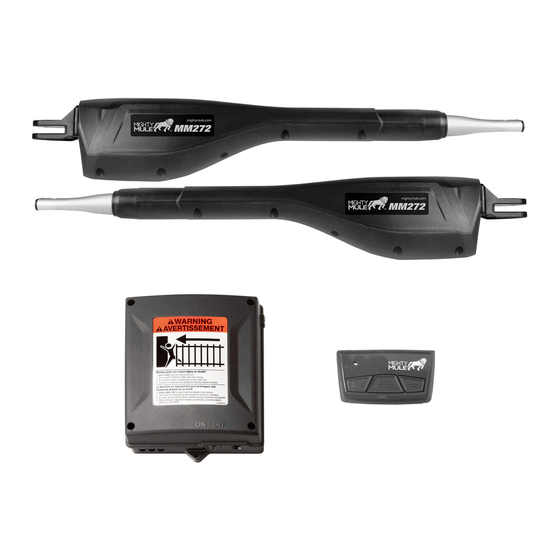
Control Box
Post Bracket
120 Volt indoor
Transformer
(surge protector
not supplied)
Run 1000' (max.) of low
voltage wire to control
box from transformer
(wire not included).
This product meets the requirements of UL325, the standard for gate operator safety.
Mighty Mule® is the retail brand of Nortek Security & Control, LLC
Installation Manual
Gate Swings Evenly and Freely
Hung Firmly and Plumb
First Gate Opener
Gate Bracket
Horizontal Support
Power Cable
12 Volt automotive or marine
type battery in weather proof
housing (REQUIRED, not included).
PVC conduit (not included)
to run second opener power
cable under driveway.
Example of finished installation
(installations vary slightly on different types of gates)
MM272
Warning Sign
Gate Bracket
Horizontal Support
Closed Position Stop Plate
Stop Plate and Low Pro le Ground Stop
Fence Post Set in Concrete
Second Gate Opener
Post Bracket
10022113 Rev-B
Advertisement
Table of Contents

Related Manuals for Mighty Mule MM272


Summary of Contents for Mighty Mule MM272
- Page 1 (wire not included). Example of finished installation (installations vary slightly on different types of gates) This product meets the requirements of UL325, the standard for gate operator safety. Mighty Mule® is the retail brand of Nortek Security & Control, LLC 10022113 Rev-B...
- Page 2 WARNING DO NOT SPLICE ANY POWER WIRES! DO NOT MODIFY THE BATTERY HARNESS! THIS WILL VOID YOUR MANUFACTURER’S WARRANTY. Low voltage wire for transformer not included.
- Page 3 WARNING This equipment meets Underwriters Laboratory Standard 325 (UL 325). However, gate equipment has hazards associated with its use and therefore by installing this product the installer and user accept full responsibility for following and noting the installation and safety instructions. Failure to follow installation and safety instructions can result in hazards developing due to improper assembly.
- Page 4 Product Usage The Mighty Mule Gate Operator meets all of the safety requirements of a Class I Residential Vehicular Gate Operator and is intended for use solely with vehicular swing gates in single-family residential applications that meet the Class I category listed in the table below.
-
Page 5: Table Of Contents
Table of Contents Please Read This First! ......................2 Manually Opening and Closing Gate ..................3 Important Safety Information ..................3 For the Installer and End User ....................4 Installing Warning Signs and Pedestrian Gates .................8 Required Safety Precautions for Gates ..................9 Technical Specifications ......................10 Before You Begin ......................11 Solar Panel and Gate Activity Chart ..................11 Parts List –... -
Page 6: Please Read This First
When correctly installed and properly used, reverse direction when it comes in contact with an your Mighty Mule Gate Operator will give you many obstruction. This is factory set to the most sensitive years of reliable service. Please read the following setting and must be adjusted during installation. -
Page 7: Manually Opening And Closing Gate
Because Mighty Mule automatic gate operators are only part of the total gate operating system, it is the responsibility of the installer and end user to ensure that the total system is safe for its intended use. -
Page 8: For The Installer And End User
ZONE 1 ZONE 2 ZONE 2 ZONE 5 ZONE 5 ZONE 3 ZONE 3 Driveway ZONE 4 ZONE 4 Entrapment Zones for a Gate in the Gate in the Open Position Open Position Pull-To-Open Application MM272 Installation Instructions... - Page 9 6. Secure outdoor or easily accessed gate operator damage. controls in order to prohibit unauthorized use of the gate. Pull-To-Open Application Moving Gate Moving Gate Area Area Driveway NEVER INSTALL any control device within gray area MM272 Installation Instructions...
- Page 10 It is your responsibility to post warning instructions and still do not understand how to signs on both sides of your gate. If any of these disconnect the operator, contact the Mighty Mule signs or warning decals becomes damaged, Service Department.
- Page 11 Entrapment Alarm The Mighty Mule Automatic Gate Operator is designed to stop and reverse the gate when the gate comes in contact with an obstruction. Additionally, these operators are equipped with an audio entrapment alarm which will activate if the unit obstructs twice while opening or closing.
-
Page 12: Installing Warning Signs And Pedestrian Gates
Installing Warning Signs and Pedestrian Gates Warning signs alert people of automatic gate operation and are required when installing Mighty Mule Automatic Gate Operators. A minimum of two WARNING SIGNS must be installed in the area of the gate. Each sign is to be visible by persons located on the side of the gate on which the placard is installed. -
Page 13: Required Safety Precautions For Gates
Maximum Gate: 300 lb. (136 kg); 12 ft. (3.65 m) Voltage: 12 Vdc; Frequency: 0 Hz; Power: 25 W E472888 Class I Vehicular Gate Nortek Security & Control – Carlsbad, CA USA 10019665A Product identi cation label (1) installed on the side of the Control box. MM272 Installation Instructions... -
Page 14: Technical Specifications
Adjustable auto-close timer (OFF to 3–120 seconds), and Dual Sense Technology™ stall force. • Power terminal block accommodates an included transformer or optional solar panels • Accessory terminal block fully compatible with all Mighty Mule access controls. • Control board allows connection of edge sensors and photoelectric sensors. •... -
Page 15: Before You Begin
• The Mighty Mule 272 is designed and intended for use with a 12 Volt automotive, marine or lawn tractor battery. The battery must be placed inside a weatherproof case and located within 6' of the control box. The 8' battery harness connects the battery to the control board. - Page 16 2. Check Direction of Gate Swing The Mighty Mule 272 is designed for PULL-TO-OPEN installations. PUSH-TO-OPEN installations require two Push-To-Open brackets [FM148]. Push-to-Open Installation Instructions begin on page Your Property Your Property 3. Prepare the Gates • Gates must be plumb, level, and swing freely on their...
-
Page 17: Parts List - Opener And Mounting Hardware
3/8" x 2-3/4" Bolt (4) 3/8" Lock Washer (10) 3/8" x 1-1/4" Bolt (2) 5/16" Washer (2) 5/16" x 1-1/4" Bolt (2) 3/8" Nut (10) 3/8" x 1-1/2" Clevis Pin (4) 5/16" Lock Nut (2) Hairpin Clip (4) MM272 Installation Instructions... -
Page 18: Tools And Materials
AC power source you will need to use at least ● Weatherproof cover for outdoor outlet and one Mighty Mule solar panel to trickle charge transformer. the battery. See the accessory catalog (Do not ● If the post is larger than 6”, bolts longer than use both transformer and solar). -
Page 19: Installation Overview For Pull-To-Open Gates
If the gate post is larger than 6" the Post Pivot Bracket can be removed and the center hole of the Post Bracket can be the mounting point for the gate opener. Center hole of post bracket MM272 Installation Instructions... -
Page 20: Installation Of The First Gate Opener
(not supplied) Muffler Clamp for Gate Bracket Thin Walled Tube Gate Wood or Metal 1" x 6" Wood Reinforcement Reinforcement Gate Bracket Gate Bracket Wood or Metal Reinforcement Panel Gate (not supplied) 1" x 6" Wood Reinforcement MM272 Installation Instructions... -
Page 21: Install Post Bracket Assembly And Gate Bracket
C-clamps to temporarily secure the post bracket assembly and gate bracket to the post and gate. Gate Bracket Hairpin Clip Post Bracket Assembly Gate in Open Position Opener Arm Fully Retracted Level Opener Gate Bracket Fence Post MM272 Installation Instructions... - Page 22 After marking your reference points, remove the opener and brackets from the fence and gate. Mark cross member through middle of gate bracket slots and drill " holes through cross member. MM272 Installation Instructions...
-
Page 23: Attach Opener Arm
NOTE: The power cable for the Second Opener should be run in PVC conduit under the driveway to protect it from damage due to lawn mowers, heavy equipment, etc. (See illustration on page 15.) NEVER SPLICE opener arm power cables. This will cause performance problems and may damage the opener. MM272 Installation Instructions... -
Page 24: Install The Closed Position Stop Plates
35). If you will be using the Mighty Mule Gate Lock with your gate opener system, the closed position ground stop is required. For Pull-to-Open systems, install the closed position stop plates on the inside of the gates. For Push-to-Open systems, install the closed position stop plates on the outside of the gates. -
Page 25: Mount The Control Box
NOTE: For optimal receiver range, mount box so antenna extends above the top of the gate. Control Box Step 2 Remove the control box cover by removing the four (4) screws. NOTE: Make sure the antenna is pointed straight up. MM272 Installation Instructions... -
Page 26: Connect Opener Power Cables
After you have measured how much wire is needed, cut the wire to ON/OFF Switch the appropriate length (up to 1000'). ON/OFF MM272 Installation Instructions... - Page 27 SOLAR terminals regardless of color/polarity. Low Voltage Wire VAR6 from Transformer Tighten set screws against exposed end of wires. A dab of household or Solar Panel ON OFF petroleum jelly on each terminal will help prevent corrosion. MM272 Installation Instructions...
-
Page 28: Connect Battery Harness To Control Board
RED battery harness wire to the RED wire (BATT + VAR4 SENSOR COMMON terminal). Wire correctly; reverse connection will damage control board. VAR5 LOCK+ LOCK– BATT + BATT – CHARGE SOLA VAR6 ON OFF Strain Relief Slots Battery Harness Cable from Battery MM272 Installation Instructions... -
Page 29: Connect The Battery
Press and HOLD the 2nd opener JOG CLOSE button on the control board and be prepared to RELEASE the button when the gate reaches the desired closed position/limit. Use the JOG OPEN and CLOSE buttons to "fine tune" the gate position if necessary. MM272 Installation Instructions... -
Page 30: Setting Dual Sense Detection And Auto Close Timer
LOCK– For safety reasons the Dual Sense Stall Force setting on the Mighty Mule control board comes from the factory set to the 10 o'clock position. This setting may need adjustment depending on the size and weight of the gate. -
Page 31: Mmt103 Transmitter
This device complies with Part 15 of the FCC Rules. Operation is subject to the following two conditions: (1) This device may not cause harmful interference, and (2) this device must accept any interference received, including interference that may cause undesired operation. MM272 Installation Instructions... -
Page 32: Push-To-Open Installation Instructions
Mount gate bracket using two " x 2 " bolts, washers, lock washers and nuts. NOTE: For mounting examples, see page CAUTION THE OPERATOR MUST BE INSTALLED WHILE FULLY RETRACTED WITH THE GATE IN THE CLOSED POSITION. MM272 Installation Instructions... - Page 33 Press the transmitter button and allow the gates to fully open to verify that they stop at the desired positions. Repeat Steps B – E if correction is needed. Step 12: Adjust Stall Force Setting (page Step 13: Set Auto Close Time (page Step 13: Personalize Transmitter Settings (page MM272 Installation Instructions...
-
Page 34: Solar Panel Instructions
NOTE: For multiple panels wire the panels in parallel as shown in this diagram. Solar Panels connect in PARALLEL After connecting the solar panel(s) connect the battery as shown on page 24. (DO NOT exceed 20 watts.) BLACK BLACK MM272 Installation Instructions... -
Page 35: Connecting Additional Devices
Connecting Additional Devices Mighty Mule strongly recommends the use of additional obstruction detection devices however we do not endorse any specific brand names. Only use products that are listed to be in compliance with any applicable UL safety standards and national and regional codes. - Page 36 12 Volt Power (Maximum Current: 100 mA) COM: Common/Negative terminal for accessory power source. LOCK +: Power source for Nortek Security & Control/Mighty Mule accessories, i.e. Gate Opening Sensor [FM138]. Lock Outputs LOCK +: Positive terminal to connect Automatic Gate Lock [FM143].
-
Page 37: Troubleshooting Guide
● Monthly, turn off the power switch and disconnect the Mighty Mule and move the gate to make sure the gate is moving freely without sticking or binding. Lubricate the hinges or repair the gate as required before reattaching the Mighty Mule. -
Page 38: Visual Feedback
Check for a stuck transmitter h Receiving RF interference Warranty Repair If your Mighty Mule Gate Opener is not operating properly, please follow the steps below: 1. First use the procedures found in the Visual and Audible Diagnostic Indicators section (page 33). -
Page 39: Accessories
Solar Panel Charging Kit. Installation in some regions of the world will require multiple solar panels for adequate charging power. Pin Lock (FM133) The Pin Lock substitutes for the clevis pin at the front end of the Mighty Mule gate openers. Helps prevent theft of the opener from the gate. MMT103 The MMT103 Code Safe digital transmitter is a wireless radio control designed for use with Mighty Mule garage door openers and can also be programmed to your Mighty Mule gate openers. - Page 40 Copyright infringement is a violation of federal law. Mighty Mule¨, E-Z Gate¨, NSC¨, “Dual Sense Technology” are registered trademarks of Nortek Security & Control, LLC, America’s DIY Automatic Gate Openers is a trademark of Nortek Security & Control, LLC and are the exclusive property of Nortek Security &...
-
Page 41: Gate Operator Installation Checklist
10. Reviewed all safety instructions, and keep the safety instructions and owner’s information sheets for ❑ reference. 11. Review and understand the maintenance schedule for both the gate and the gate operator. ❑ MM272 Installation Instructions... - Page 42 Copyright infringement is a violation of federal law. Mighty Mule¨, E-Z Gate¨, NSC¨, “Dual Sense Technology” are registered trademarks of Nortek Security & Control, LLC, America’s DIY Automatic Gate Openers is a trademark of Nortek Security & Control, LLC and are the exclusive property of Nortek Security &...
- Page 43 MM272 Installation Instructions...
Need help?
Do you have a question about the MM272 and is the answer not in the manual?
Questions and answers