Table of Contents
Advertisement
Advertisement
Chapters
Table of Contents

Related Manuals for AT&T Partner Series


Summary of Contents for AT&T Partner Series
- Page 1 AT&T PARTNER™ Communications System Installation and Use...
- Page 2 AT&T 999-506-139 Copyright © 1990 AT&T Issue 2 All Rights Reserved October 1990 Printed in U.S.A. Notice Every effort was made to ensure that the information in this document was complete and accurate at the time of printing. However, information is subject to change. Federal Communications Commission (FCC) Information For important FCC interference, registration, and repair information, see appendix D of this document.
-
Page 3: Table Of Contents
Contents About This Guide System Overview Features and Capabilities System Components Optional Equipment Specifications Quick Start Installing the Hardware Before You Start Installing System Modules Connecting Equipment 2-14 Replacing Modules Customizing Your System Overview Changing Factory Settings Speed Dialing Auto Dialing Special Dialing Functions Basic Call Handling with PARTNER Phones PARTNER Phone Controls... - Page 4 Using Standard Telephones Overview Call Handling Using Optional Equipment Fax Machines Answering Machines Modems 6-11 Credit Card Scanners 6-12 Troubleshooting Maintenance and Customer Support Use Behind PBX or Centrex User Form Ordering Information FCC Information Upgrading Your System Index IN-1...
- Page 5 About This Guide This guide provides instructions on how to set up and use the PARTNER™ Communications System. How to Use This Guide If you are installing and using your PARTNER system for the first time, we recommend that you read chapters 1 through 5 to Iearn what the PARTNER system can do.
- Page 6 System Overview Contents Features and Capabilities System Components Optional Equipment Industry Standard Devices Limitations Connecting and Using Standard Devices Other Devices Ordering Information Specifications Quick Start...
-
Page 7: Features And Capabilities
Features and Capabilities Your PARTNER™ system is easy to install, set up, and use. The best way to get started with the PARTNER system is to read this manual straight through. If you’re in a hurry to set up and use the system, you can read this chapter and use the Quick Start table on page 1-6. -
Page 8: System Components
System Components MODULE CONNECTOR 206 MODULE This connector is needed only if you A system can have one or two 206 have two 206 modules. It joins the modules. Each 206 module connects Circuit Breakers modules together so that all the lines up to 2 telephone company lines and telephones on both modules are and up to 6 telephones or other... -
Page 9: Optional Equipment
Optional Equipment The PARTNER system works with many telecommunications devices, not only PARTNER telephones. You can connect these other devices without investing in more lines or circuit cards. Industry Standard Devices Many types of industry-standard telecommunications devices will work with your PARTNER system. -
Page 10: Connecting And Using Standard Devices
Connecting and Using You can connect the standard device so that it is on an extension by itself, or it can share an extension with another piece of equipment (either another stan- Standard Devices dard device or a PARTNER phone). To connect two devices on one extension, you will need an AT&T 267F2 bridging adapter. -
Page 11: Specifications
Specifications Table 1-1 System Specifications Capacities System 206 Module Extension Jack (with two 206 modules) 2 outside lines Maximum 2 devices per exten- 4 outside lines 6 extensions sion jack, total REN not to 12 extensions exceed 2* (2 devices require AT&T 267F2 bridging adapter) Dimensions Single 206 Module... -
Page 12: Quick Start
Quick Start To get started quickly, refer to the figure below for the important steps you must follow to install and set up the system. Refer to the pages listed to find the addi- tional information you need. Check the System Wiring page 2-1 Install the... - Page 13 Installing the Hardware Contents Before You Start Check for Outside Lines Check for Inside Wiring If There Is Wiring If There Is No Wiring Preparing for a Power Failure Installing System Modules Connecting Equipment PARTNER Telephones 2-12 Connecting Standard Single-Line Equipment 2-13 Combining Two Devices on One Extension Replacing Modules...
-
Page 14: Before You Start
Before You Start Before installing your PARTNER system, you must make sure the system wiring is ready. This wiring includes both the outside Iines from the local telephone company and the inside wiring for connecting extensions to the 206 modules (also called system modules). - Page 15 Check for Inside Wiring Inside wiring (also called “building wiring”) enables you to connect phones and other equipment to the 206 modules. If the building is already wired, the follow- ing section tells you whether or not the wiring will work. If the building is not wired, you can have it professionally wired or wire it yourself, as described on the next page.
- Page 16 If There Is No Wiring If there is no inside wiring, or the existing wiring is not acceptable, you can install your own wiring. The type of wiring you use depends on how far the extension is from the system module(s). For extensions that are within 14 feet: use the telephone cords included with the system.
-
Page 17: Installing System Modules
Installing System Modules If your PARTNER system has only one mudule, you can install it on a wall or on a flat sturdy surface above the floor (such as on a table or desk). Wall mounting is recommended. Complete step 1 below and continue as directed. If your PARTNER system has two modules, you must install it on a wall. - Page 18 Add the Second Module (for 2-module systems only) A system with two modules must be wall-mounted. Side View Front View Mounting Tracks Attach the module connector to Slide the second module onto the Remove the plastic protector from the top right side of the two modules. the connectorr on the right side of the first module.
- Page 19 Connect Incoming Telephone Lines Before connecting the telephone company lines, test for dial tone at the network interface jack (step 10). These jacks are the lines from the local telephone company. If you do not hear a dial tone on one or more of the incoming lines, contact your local phone company and ask a representative to check...
- Page 20 Test the System Testing the system includes testing the modules and incoming lines through the modules. 1-Module System 2-Module System Make sure the circuit breakers on Connect the AC power cord to Plug the other end of the power each 206 module are pressed down. In the 206 module on a system with one cord into a grounded wall outlet.
- Page 21 Connect Modular Telephone Cords CAUTION: Disconnect the AC power cord before continuing. If you are connecting phones and other equip- ment directly to the mod- ules, go to step 20. If you are using the Extension Wiring Kit for additional wiring, install that now.
-
Page 22: Connecting Equipment
Connecting Equipment PARTNER Telephones You can install a PARTNER phone on a desk or wall. Follow the instructions below for desk mounting. For wall mounting, see the next page. The telephone stand packed with the PARTNER phone is required for wall mounting, optional for desk mounting. To connect a PARTNER phone to the system, use only the 2-pair (4-conductor) telephone cords included with the phone. - Page 23 On a Wall: For a neater mounting, use a shorter, 2-foot mounting cord (AT&T’s D4BU-29). To order, see appendix C. For proper mounting, the wall jack must be an AT&T 630B series connecting or mounting block. Insert the cord through the center Reverse the plastic hook that sits To attach the stand to the base of of the stand and plug it into the jack on...
- Page 24 Insert the Button Label Sheet To remove the clear plastic cover Place the button label sheet on Replace the plastic cover. from the phone, gently press down on the phone. The holes on the sheet the center tab, then lift. should fit over the buttons.
- Page 25 Your PARTNER Communications System should be ready to use. However, if— the system is connected to a PBX or Centrex system, you may need to change certain system settings. See appendix A. your local telephone company uses rotary lines instead of touch-tone lines, you must change your system’s Dial Mode from touch-tone to rotary.
- Page 26 Combining Two Devices on One Extension You can combine a PARTNER phone of another standard device or two standard devices on one extension. The total REN (Ringer Equivalence Number) for the devices must be 2 or less (see p. 1-3). Do not combine two PARTNER phones on one extension jack.
-
Page 27: Replacing Modules
Replacing Modules On a one-module system, follow steps 3-5 below. On a two-module system, start at step 1. CAUTION: Unplug the AC power cord from the system before starting. After unplugging the power cord, Slide off the top module. If re- Remove the screws used to remove the screws on the connector. - Page 28 Customizing Your System Contents Overview Changing Factory Settings Outgoing Call Restriction Automatic Line Selection Line Ringing Abbreviated Ringing Speed Dialing Auto Dialing Special Dialing Functions Alphabetical List of Customization Features Abbreviated Ringing Auto Dialing Automatic Line Selection Call Restriction, Outgoing Line Ringing Line Selection, Automatic Outgoing Call Restriction...
-
Page 29: Overview
Overview After completing the installation steps in chapter 2, your system is fully operational and ready to go. All the system’s settings are preset and require no adjustment. However, if you want, you can customize your system to meet your specific needs by changing some of the factory settings. -
Page 30: Changing Factory Settings
Changing Factory Settings The system’s factory settings can be changed only from extension 10 using a PARTNER phone. You can change settings anytime, even when you are on a call. This allows you to change settings while talking on the AT&T Helpline. Just remember that (except for Auto Dialing) you must change settings from exten- sion 10 using a PARTNER phone. - Page 31 Automatic Line Selection If you have a two-module system with four lines, the system is set at the factory to connect you automatically to lines in the following order: Outside Line 1, 2, 3, 4, Intercom. If you have a system with one 206 module, the system connects you in the following order: Outside Line 1,2, Intercom.
- Page 32 Line Ringing Line Ringing lets you set all, some, or no outside lines to ring on each individual extension. The factory setting is for each outside line to ring on all extensions. Change this setting if you want one or more lines on any extension not to ring. If you want to set up your system Procedure: so that all incoming calls come...
-
Page 33: Speed Dialing
Speed Dialing Speed Dialing allows you to store up to 10 outside numbers in the system’s memory. Any user can dial these numbers automatically by pressing only three buttons. Speed Dialing saves time and effort, and can spare people from con- stantly looking up telephone numbers. -
Page 34: Auto Dialing
Auto Dialing With Auto Dialing, anybody with a PARTNER 12-button phone can store up to eight outside phone numbers on Auto Dial buttons. This allows the number to be dialed with a single touch. Any user can store Auto Dial numbers on his or her phone. -
Page 35: Special Dialing Functions
Special Dialing Functions You can add these special functions to any Auto Dial or Speed Dial number: Pause. A pause causes the dialing sequence to stop for 1.5 seconds. You might need a pause when dialing into a different long distance service or when dialing an international number. - Page 36 Basic Call Handling with PARTNER Phones Contents PARTNER Phone Controls Lights Ringing Patterns Using the Speaker and Microphone Hands-Free Answer on Intercom (HFAI) Using the Auto Dial Buttons Call Handling Using the Speakerphone A Word about Dial Tones Making an Outside Call Making an Intercom Call Answering a Call Putting a Call on Hold...
-
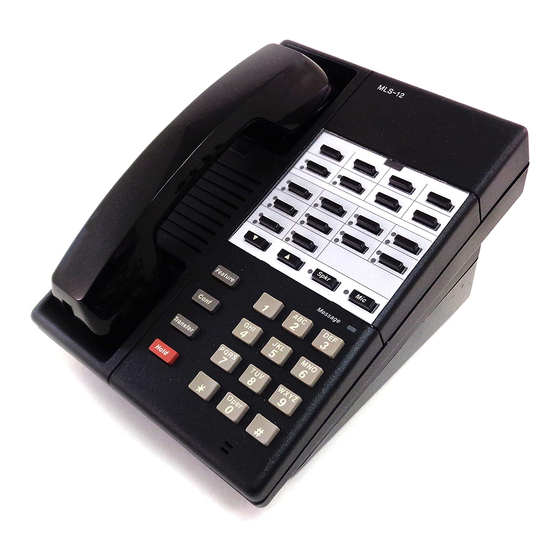
Page 37: Partner Phone Controls
PARTNER Phone Controls Figure 4-1 shows the buttons and indicators on the PARTNER 12-button telephone. (The PARTNER 6-button telephone is not shown. It is the same as the PARTNER 12-button phone except that it has no Auto Dial buttons, Calling Feature buttons, or built-in microphone.) AT&T MLS-12... -
Page 38: Lights
Lights To the left of each line and intercom button is a green and a red light. These lights flash in different ways to show what is happening on that line. The green light shows activity at your extension; the red light shows activity at other exten- sions. -
Page 39: Using The Speaker And Microphone
Using the Speaker and Microphone Both PARTNER telephones have a speaker, which you can turn on by pressing ]. The PARTNER 12-button telephone also has a microphone, which you Spkr can turn on by pressing [ ]. When the green light next to the button is on, the speaker or microphone is on. -
Page 40: Using The Auto Dial Buttons
Using the Auto Dial Buttons Anyone with a PARTNER 12-button telephone can use the Auto Dial buttons (shown in figure 4-1) to personalize his or her phone. See p. 3-6 for instructions on how to store an Auto Dial number while working from extension 10. To store an Auto Dial number: Press [ Feature... -
Page 41: Call Handling
Call Handling In this section you will learn how to handle calls using PARTNER phones, and how to use the system’s built-in calling features. The information given here is a more detailed version of the information on the Quick Reference. We recom- mend that you read this chapter first, and then use the Quick Reference as a reference. -
Page 42: Making An Outside Call
Making an Outside Call To make an outside call: Press any idle line button. (An idle line button is one that is not lit.) The light next to the line button is steady green. Lift the handset. Dial the number. If you lift the handset before pressing an outside line button, you will be automatically con-... -
Page 43: Answering A Call
To make a voice-signaled intercom call (to another PARTNER phone only): Press either [ ] button. Intercom Lift the handset. The green light appears and you hear the intercom dial tone. Press [ ] and the 2-digit extension number. After you hear a short beep, If you have a PARTNER 12- button phone, and you leave the speak into the handset. -
Page 44: Transferring A Call
Transferring a Call To transfer a call means to pass the call from one phone to another. You can only transfer outside calls; you cannot transfer intercom calls. There are three ways to transfer a call: A transferred call will ring like an Announce the call when it is picked up. -
Page 45: Making A Conference Call
Making a Conference Call A conference call connects you with two other parties—outside or inside—in a single call. During the conference call, any inside party can exit the call at any time by hanging up. However, if an outside party hangs up during a conference call, the callers that remain on the conference will hear a dial tone. -
Page 46: Joining A Call
Joining a Call You can connect yourself to an outside call being conducted at another exten- sion. This is called joining. For example, if John is on an outside call and wants you to participate in that call, you can join in simply by pressing the button of the line John is on. -
Page 47: Built-In Calling Features
Built-In Calling Features Four built-in calling features help you make and handle calls. On a PARTNER 12-button phone, use each feature by pressing its calling feature button, as shown in figure 4-2. On a PARTNER 6-button telephone, use the feature by pressing [ ] and a 2-digit dial code, also shown on the figure. - Page 48 Using Standard Telephones Contents Overview Setting Up Extensions for Standard Phones Using the Switchhook Using Feature Phones Call Handling Making an Outside Call Making an Intercom Call Answering a Call Ringing Patterns Putting a Call on Hold Transferring a Call Making a Conference Call Speed Dialing Using Calling Features...
-
Page 49: Overview
Overview The call handling procedures in You can connect standard touch-tone or rotary dial phones directly to the this chapter are meant to be system without expensive adapters or connecters. Standard phones can do photocopied and given to those many of the things that the PARTNER phones can do, but because standard users with standard phones. -
Page 50: Call Handling
Call Handling Making an Outside Call To make an outside call: Lift the handset. You hear the intercom dial tone. Dial [ ] to get an outside line. You hear the outside line dial tone. Dial the number. Making an Intercom Call To make a ringing intercom call: Lift the handset. -
Page 51: Putting A Call On Hold
Putting a Call on Hold To put a call on hold: While active on the call . . . Rapidly press and release the switchhook. You hear the intercom dial tone. The call is on hold. Do not hang up the handset while the call is on hold. -
Page 52: Making A Conference Call
Making a Conference Call A conference call connects you with two other parties—outside or inside—in a single call. You set up a conference call by adding a second party to an exist- ing call. To add a second party to an existing call: You are connected with the first party . -
Page 53: Speed Dialing
Speed Dialing To dial a Speed Dial number (from a touch-tone phone only): Lift the handset. You hear the intercom dial tone. Press [ ] plus the 2-digit Speed Dial code (20 to 29). The system automatically selects an outside line and dials the Speed Dial number. -
Page 54: Using A Combination Extension
Using a Combination Extension A combination extension is a PARTNER telephone and a standard telephone (or other standard device) that share a single extension. For complete instructions on how to install a combination extension, see p. 2-13. The following are examples of useful combination extensions: PARTNER phone plus standard telephone, for power failure backup (exten- sions 10 and 16). - Page 55 Using Optional Equipment Contents Fax Machines Fax Machine with Its Own Fax Line Fax Line Saver Fax and Telephone Combination Backup Fax Machine Transferring a Call to the Fax Machine Using the Fax Machine’s “Notify” Feature Answering Machines Retrieving Messages From the Answering Machine Single Answering Machine Personal Answering Machine Multiple Answering Machines...
-
Page 56: Fax Machines
Fax Machines The benefit of connecting a fax machine to your PARTNER system To install a fax machine, see is that you can set up the fax machines in different ways to suit your needs. By p. 2-12. using the lines connected to your system, you do not have to pay for an additional fax line. -
Page 57: Fax Machine With Its Own Fax Line
Fax Machine with Its Own Fax Line In this setup, which is good for heavy fax traffic, line B is the fax line, the number of which is published as the fax number (figure 6-1). (This fax line can also be used by other phones when all other lines are busy.) The fax machine is con- nected to its own extension (extension X). -
Page 58: Fax Line Saver
Fax Line Saver If you don’t use your fax machine enough to justify paying for its own outside line, you can put the fax on its own extension if you don’t mind manually transferring calls to it (figure 6-2). lines MODULES e x t Figure 6-2 Fax Machine Line Saver... -
Page 59: Fax And Telephone Combination
Fax and Telephone Combination If you want to connect a fax machine but cannot spare an extra extension, or if your fax machine does not have a built-in telephone, you can connect a tele- phone and a fax machine to a single extension via an AT&T 267F2 bridging adapter (figure 6-3). -
Page 60: Backup Fax Machine
Backup Fax Machine If your business absolutely depends on receiving fax messages—if reliability is essential—you can set up two fax machines so that one serves as a backup for the other. In the example shown in figure 6-4, fax machine 1 is set up as the pri- mary machine;... -
Page 61: Transferring A Call To The Fax Machine
Transferring a Call to the Fax Machine There are two situations in which you would want to transfer a call to your fax machine: You answer an outside call and hear a fax machine signaling. (A fax signal is a single beep sequence— BEEP . . . BEEP . . . BEEP). If you hear this, you should transfer the call immediately to the fax machine extension. -
Page 62: Answering Machines
Answering Machines You can use an answering machine to answer calls at night when no one is around, or during business hours when no one can get to the phone. The fol- To install an answering machine, lowing are ways you can connect answering machines to your system: see p. -
Page 63: Single Answering Machine
Single Answering Machine The single answering machine setup (figure 6-5) serves the entire system. It is connected to its own extension and covers all the lines in the system, one at a time. lines MODULES MACH Figure 6-5 Single Answering Machine To set up: Do not adjust the answering 1. -
Page 64: Personal Answering Machine
Personal Answering Machine A personal answering machine (figure 6-6) is used to answer all the calls that ring on the lines at a certain extension. It is useful for the following situations: When the extension receives a lot of intercom calls When outside calls come through a receptionist and are transferred to the extension lines... -
Page 65: Multiple Answering Machines
Multiple Answering Machines If a single answering machine cannot handle all your calls, you can set up two or more machines to answer (figure 6-7). A setup such as this might be used by a movie theater to announce show times to people calling in for information. lines A MODULES MACH... -
Page 66: Modems
Modems You can connect a modem directly to an extension jack without an adapter. A modem and a terminal allow you to dial out and connect to computer bulletin To install a modem, see p. 2-12. boards and other data services. The setup is shown in figure 6-8. Note that the 267F2 bridging adapter and telephone are optional, and can be used if you want the terminal to share an extension with a phone. -
Page 67: Credit Card Scanners
Credit Card Scanners Many retail businesses and restaurants use credit card scanners (figure 6-9) to To install a credit card scanner, get instant approval for credit card purchases. The PARTNER system allows see p. 2-12. your credit card scanners to share the lines in your system. lines CONTROL UNIT... - Page 68 Troubleshooting Contents When You Have a Problem All Phones Dead: No Dial Tone or Lights PARTNER Phone Does Not Work Trouble Making Outside Calls Phone Does Not Ring Calls are Answered Automatically Using the Recall Feature Has No Effect Using the Recall Feature Disconnects Call Calls on Hold Are Disconnected Call on Hold Hangs Up, but Line Does Not Disconnect Standard Phone Rings After Intercom Call With No One at Other End...
-
Page 69: When You Have A Problem
When You Have a Problem If you should have a problem with your system, there is a good chance you can solve it by following the appropriate procedure in this section. If you cannot solve the problem by following the procedures in this section, call: The helpline is open 24 hours a National Service Assistance Center Helpline day. -
Page 70: Partner Phone Does Not Work
PARTNER Phone Does Not Work If... Then: Do This Possible Cause The problem remains, Go to Possible Cause 2. 1. Phone needs to be Unplug the cord from the reset. bottom of the phone and plug it in again. lMPOR- TANT: Make sure the handset is hung up when you plug in the cord. -
Page 71: Trouble Making Outside Calls
Trouble Making Outside Calls Trouble making outside calls could be one of the following: You hear a dial tone, but the dial tone continues as you try to dial. You hear a dial tone, and the dial tone cuts off when you dial, but the line does not ring. You hear a busy signal as you dial. -
Page 72: Phone Does Not Ring
Phone Does Not Ring Then: Do This If... Possible Cause Phone rings increasingly Problem is solved. 1. Volume control set Press the volume control louder, too low. button to increase ringer volume. Phone still does not ring, Go to Possible Cause 2. Change setting if neces- Line Ringing is set for "no 2. -
Page 73: Using The Recall Feature Has No Effect
Using the Recall Feature Has No Effect Possible Cause Do This If... Then: 1. Recall Timer Dura- Increase the Recall Timer The Recall feature works, The problem is solved. tion set too short. Duration. The Recall feature still Continue increasing the On a PARTNER phone at doesn’t work, interval by increments of 4... -
Page 74: Calls On Hold Are Disconnected
Calls on Hold Are Disconnected Before using the following procedure, make sure that the calls on hold are not being disconnected because the callers are hanging up. Then: If... Possible Cause Do This The problem is solved CalIs on hold are no 1. -
Page 75: Standard Phone Rings After Intercom Call With No One At Other End
Standard Phone Rings After Intercom Call with No One at Other End Possible Cause Do This If... Then: Automatic Line If one of the phones is a The problem is not solved, Call 1 800 628-2888 Selection is set standard telephone, set its incorrectly. -
Page 76: Combination Extension Problem: Partner Phone Lights Show Line Is Busy
Combination Extension Problem: PARTNER Phone Lights Show Line Is Busy Then: If... Do This Possible Cause Problem is solved. PARTNER phone light Hang up standard phone. Standard phone is goes off, not hung up. Reset PARTNER phone Standard phone is hung according to procedure given under "PARTNER Phone Does Not Work."... - Page 77 Maintenance and Customer Support Contents Maintenance 206 Modules Telephones Customer Support Warranty and Post-Warranty Repair In-Warranty Repairs Post-Warranty Repairs AT&T Limited Warranties Commercial Use Consumer Use...
-
Page 78: Maintenance
Maintenance Your PARTNER system is designed to provide trouble-free performance without any special maintenance procedures. However, there are a few precautions you can take to prevent accidental damage to your system. 206 Modules To prevent damage to the 206 modules: Keep the modules in an area free of dust, smoke, and moisture. -
Page 79: Customer Support
Customer Support AT&T customer support personnel can help you program or use the system and telephones. In the U.S., call the following toll-free number 24 hours a day: AT&T General Business Systems National Service Assistance Center Helpline 1 800 628-2888 In Canada, call the nearest Technical Assistance Center: Eastern Canada and Ottawa: 1 800 363-1882... -
Page 80: At&T Limited Warranties
AT&T Limited Warranties Commercial Use The following AT&T limited warranty and limitation of liability will apply if you have purchased your PARTNER Communications System ("System") primarily for commercial purposes. AT&T Commercial Warranty AT&T warrants to you that your System will be in good working order when you take title and that it will remain in good working order for a period of one year (the warranty period) or AT&T will, at its option, repair or replace the system com- ponent that is not in good working order. -
Page 81: Consumer Use
Consumer Use The following AT&T limited warranty will apply if you have purchased your PARTNER Communications System ("System") primarily for personal, family, or household purposes. AT&T Consumer Warranty What is covered: Any defect in material and workmanship. For how long: One year. What we will do: If your System is defective within one year of the date of purchase, we will repair it or, at our option, replace it at no charge to you. - Page 82 Use Behind PBX or Centrex If you are connecting your PARTNER system to a PBX (Private Branch Centrex is a business telephone Exchange) or Centrex system, instead of directly to local telephone company service offered by your local lines, you must make sure your system is set up correctly. This involves the phone company that offers following system setting: Custom Calling features.
- Page 83 User Form We recommend that you photocopy this dial form and give it to system users for Suggestion: Make a photocopy before filling the form in, and their reference. It provides space on which to write Speed Dial numbers and keep the original clean so that system extension numbers.
- Page 84 PARTNER™ COMMUNICATIONS SYSTEM AT&T SPEED DIAL NUMBERS SYSTEM EXTENSION NUMBERS To dial a Speed Dial Number: To dial an extension: On a PARTNER (MLS-model) Telephone: On a PARTNER (MLS-model) Telephone: Press [ Feature ] + Code Press [ Intercom ] + Ext. number For example: [ Feature ] [ 2 ] [ 0 ] For example: [ Intercom ] [ 1 ] [ 3 ] To voice-signal a PARTNER phone:...
- Page 85 Product Ordering Information Ordering additional telephones and modules, accessories, and replacement parts for your PARTNER system is convenient. The table on the next page shows where you can buy them in the U.S. You can obtain most items from more than one source, either directly from AT&T or from authorized dealers.
- Page 86 To use the table, first locate the item you want. A triangle ( ) indicates where you can obtain it. SOURCE (U.S.) AT&T AT&T AT&T AT&T AT&T Authorized Catalog Sales PhoneCenter National Parts General Business Dealer Sales Center (Sourcebook) Systems Sales Store Office (800) 222-PART...
- Page 87 FCC Information Federal Communications Commission (FCC) Warning Statement This equipment has been tested and found to comply with the limits for a Class B digital device, pursuant to Part 15 of FCC rules. These limits are designed to provide reasonable protection against harmful interference in a commercial or residential installation.
- Page 88 The telephone number(s) you will be using with this equipment. The appropriate registration number and ringer equivalence number (REN), which can be found on the right hand side of the control unit. The facility interface code, which is 02LS2. You must also notify your local telephone company if and when this equip- ment is permanently disconnected from the line(s).
- Page 89 Upgrading Your System Your PARTNER system can be easily upgraded to a more advanced version, without discarding the modules, phones, and other equipment you have now. This advanced version is the affordable PARTNER™ Plus Communications System. The PARTNER Plus system gives you more capacity and many more features than your basic system.
- Page 90 can be in English, Spanish, or French, and shows the date and time, how long you are on a call, and the extension that is calling you. The display is also used for user-friendly programming. That is, the display prompts you to enter data and makes programming the system a simple task.
- Page 91 Index Electrical requirements and specifications, 1-5 1-pair D2R mounting cords, 1-5, 2-12, 2-13, C-2 Emergency phone numbers, 3-5, 3-6 206 modules, 1-2, 1-5, 2-4 to 2-8, 2-14, 8-1, C-2 Environmental requirements, 1-5 267F2 bridging adapter, 1-5, 2-3, 2-13 Extension 10, 2-3, 3-2 Extension jacks, 1-2, 1-5, 2-4, 2-5, 2-8 Extra alerts, 1-4, 2-12 Abbreviated Ringing, 3-1, 3-4...
- Page 92 Restricting outgoing calls, 3-2 Line ringing, 3-1, 3-4 Retrieving a held call, 4-7, 5-3 Lines, testing during installation, 2-7 Ringer Equivalence Number (REN), 1-5 Loudspeaker paging systems, 1-4, 2-13 Ringing patterns, 4-2, 5-2 RJ11 jack, 1-5, 2-1, 2-6 Rotary service, 2-12 Rotary telephones, see Standard Phones Maintenance, modules and telephones, 8-1 Making calls, 4-6 to 4-7, 4-9, 5-2, 5-4...
- Page 93 SPEED DIAL NUMBERS CHANGING FACTORY SETTINGS (p. 3-5) AT EXTENSION 10... AT EXTENSION 10... PRESS [ Feature PRESS [ TO STORE Feature PRESS the left [ ] button twice. Intercom PRESS [ ] followed by a 2-digit code (20–29) Feature Follow the boxed instructions below for the setting DIAL telephone number (maximum 20 digits and special functions—see box below)
- Page 94 Issue 2, October 1990 Comcode 106431307 999-506-139 Graphics © AT&T 1988...
Need help?
Do you have a question about the Partner Series and is the answer not in the manual?
Questions and answers