Sign In
Upload
Manuals
Brands
Leuze Manuals
Accessories
LES 36 Series
User Manuals: Leuze LES 36 Series measurement sensor
Manuals and User Guides for Leuze LES 36 Series measurement sensor. We have
1
Leuze LES 36 Series measurement sensor manual available for free PDF download: Original Operating Instructions
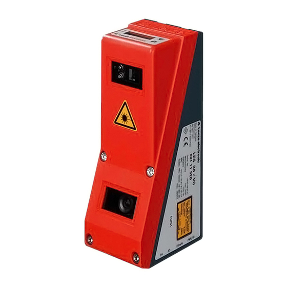
Leuze LES 36 Series Original Operating Instructions (152 pages)
Light Section Sensors
Brand:
Leuze
| Category:
Accessories
| Size: 6 MB
Table of Contents
Table of Contents
3
Leuze Electronic LES 36
10
Figures and Tables
11
Leuze Electronic LES 36
12
1 General Information
13
Explanation of Symbols
13
Declaration of Conformity
13
2 Safety
14
Intended Use
14
Foreseeable Misuse
15
Competent Persons
15
Exemption of Liability
16
Laser Safety Notices
16
Figure 2.1: Laser Apertures, Laser Warning Signs
17
Figure 2.2: Laser Warning and Information Signs - Supplied Stick-On Labels
18
3 Operating Principle
19
Generation of 2D Profiles
19
Figure 3.1: Light Section Sensor Design
19
Limits of Light Section Sensors
20
Occlusion
20
Figure 3.2: Occlusion
20
Possible Measure against Laser Occlusion
21
Possible Measures against Receiver Occlusion
21
Resolution
22
Figure 3.3: Typical Resolution LES 36
22
Figure 3.4: Typical Minimum Object Size LES 36HI
22
4 Device Description
23
Overview of Light Section Sensors
23
Mechanical Design
23
General Performance Characteristics
23
Figure 4.1: Mechanical Design of Leuze Light Section Sensors
23
Line Edge Sensor - LES
24
Specific Performance Characteristics
24
Typical Areas of Application
24
Operating the Sensor
25
Connection to PC / Process Control
25
Configuration
25
Measurement Operation
25
Activation - Laser On/Off
25
Figure 4.2: Activation Input Signal Sequence
25
Triggering - Free Running
26
Figure 4.3: Trigger Input Signal Sequence
26
PROFIBUS Trigger
27
Cascading
27
Trigger Settings
27
Cascading Settings
27
Figure 4.4: Signal Sequence for Cascading
27
Figure 4.5: Cascading Application Example
27
Measurement Functions: LES
28
Functional Principle of Object and Edge Detection with the LES
28
Inspection Task
29
Edge Analysis Window (EAW)
29
Characteristics of Eaws
29
Definition of Eaws and Their Analysis Results
30
Edge Detection
30
Figure 4.6: Edge Detection with Eaws
30
Figure 4.7: Meaning of Sequent Hits for Edge Detection
31
Figure 4.8: Edge Detection with Eaws
32
Relative Window Positioning
33
Figure 4.9: Edge Detection with Varying Object Position
33
Object Detection
34
Application Examples for Eaws
35
Application Example: Web-Edge Measurement
35
Figure 4.10: Application Example: Web-Edge Measurement
35
Application Example: Height and Width Measurement of a Cubic Object
36
Figure 4.11: Application Example: Height and Width Measurement of a Cubic Object
36
Analysis Window (AW)
37
5 Installation and Mounting
38
Storage, Transportation
38
Unpacking
38
Figure 5.1: Device Name Plate LES
38
Mounting the LES
39
Figure 5.2: Fastening Options
39
Figure 5.3: Mounting Example LES
39
BT 56 Mounting Device
40
Figure 5.4: BT 56 Mounting Device
40
BT 59 Mounting Device
41
Figure 5.5: BT 59 Mounting Device
41
Device Arrangement
42
Selecting a Mounting Location
42
Aligning the Sensor
42
Attach Laser Warning Sign
43
Cleaning
43
Figure 5.6: Alignment to the Measuring Plane
43
6 Electrical Connection
44
Figure 6.1: Location of the Electrical Connections
44
Figure 6.2: Connections of the LES
44
Safety Notices
45
Shielding and Line Lengths
46
Shielding
46
General Shielding Information
47
Connect the Ground Potential to the Light Section Sensors
47
Figure 6.3: Connecting the Ground Potential to the Light Section Sensor
47
Connecting the Cable Shielding in the Switch Cabinet
48
Connecting the Cable Shielding to the PLC
48
Figure 6.4: Connecting the Cable Shielding in the Switch Cabinet
48
Figure 6.5: Connecting the Cable Shielding to the PLC
48
Connecting
49
Connection X1 - Logic and Power
49
Power Supply
49
Activation Input Inact
49
Trigger Input Intrig
49
Figure 6.6: Internal Wiring at X1
49
Cascading Output Outcas
50
Output "Ready" Outready
50
Connection X2 - Ethernet
50
Ethernet Cable Assignment
50
Figure 6.7: HOST / BUS in Cable Assignments on RJ-45
50
Connection X3 - Switching Inputs/Outputs (LES 36
51
Switching Outputs of Connection X3
51
Switching Inputs of Connection X3
51
Connection X4 - PROFIBUS DP (LES 36
52
Connection X4 - Voltage/Current Output (LES 36
53
Characteristic Curve of Analog Output
53
Figure 6.8: Response of Analog Output LES
54
7 Display and Control Panel
55
Indicators and Operational Controls
55
LED Status Indicators
55
Control Buttons
55
Figure 7.1: Indicator and Operating Elements of the LES
55
Indicators in the Display
56
Alignment Aid
56
Status Indicator
56
Command Mode
57
Menu Description
58
Structure
58
Operation/Navigation
61
Menu Navigation
61
Selecting Values or Selection Parameters for Editing
61
Editing Value Parameters
61
Editing Selection Parameters
61
Reset to Factory Settings
62
Interrupting a Reset
62
Executing a Reset
62
8 Commissioning and Configuration
63
Switching on
63
Establish Connection to PC
63
Setting the Default Gateway
64
Setting an Alternative IP Address on the PC
64
Commissioning
65
9 Lessoft Configuration Software
66
System Requirements
66
Installation
66
Possible Error Message
72
Device List Update
73
Starting Lessoft/Communication Tab
74
Figure 9.1: Initial Screen Lessoft
74
Figure 9.2: PROFIBUS Settings
76
PROFIBUS Settings (Only LES 36/PB and LES 36HI/PB)
76
Parameter Settings/Parameters Tab
77
Standard Tab - Task Parameters Panel
77
Inspection Task Selection
77
Figure 9.3: Parameter Settings Lessoft
77
Operation Mode
78
Activation
78
Trigger Output Mode
78
Light Exposure
78
Field of View
79
Apply Settings
79
Standard Tab - Analysis Functions Panel
79
Edit Analysis Windows
79
Using the Mouse
80
Figure 9.4: Edit Analysis Windows
80
Keyboard Input
81
Position Type
81
Relative to Edge
81
Offset X / Offset Z
81
Edge Detection Definitions
81
Analysis Window Definitions
82
Edit Logical Combinations
83
Edge State (Result of Edge and Object Detection)
83
Figure 9.5: 'Edge Analysis Window Combination Tables' Window
83
Object Point/Eaw State (Result of Edge Detection)
84
Show Edge
84
X, Width (X), Z, Height (Z)
85
Profibus Inputs 1 , Profibus Inputs 2
85
Application Example 1: Web Edge Measurement
86
Application Example 2: Height and Width Monitoring of Cubic Objects
87
Additional Object Detection with LES Sensors
88
Eaw1
88
AW Logic
88
Analysis Depth
88
AW Logic Analysis Depth (Result of Object Detection)
89
Application Example 3: Width Monitoring of Cubic Objects with Object Detection
90
Are Not to be Detected)
90
Detection
91
Standard Tab - Single Shot Mode Panel
92
Standard Tab - Global Parameters Panel
92
Analog Output Tab - Configuring the Analog Output (Only LES 36
93
Edge
93
Output Mode
93
Data
93
MM for Min. Val
94
MM for Max. Val
94
Menu Commands
95
Saving Parameter Settings/File Menu
95
Transmitting Parameter Settings/Configuration Menu
95
Zoom and Pan/Toolbar
96
Definition of Inspection Tasks
96
Typical Procedure
96
10 Integrating the LES in the Process Control (Ethernet)
98
General Information
98
Protocol Structure: Ethernet
98
Protocol Structure
99
Header
99
10.2.1 Command Number
99
10.2.2 Packet Number
99
10.2.3 Transaction Number
99
10.2.4 Status
100
10.2.5 Encoder High / Low
100
10.2.6 Scan Number
101
10.2.7 Type
101
10.2.8 Number of User Data Words
101
10.2.9 Evaluation Telegram
101
Ethernet Commands
103
10.3.1 Elementary Commands
104
10.3.2 Commands in Command Mode
105
Explanation of User Data in Command Mode (Command Parameters)
106
Set Laser Gate
106
Set Actual Inspection Task
106
Get Actual Inspection Task
106
Set Scan Number
107
Set Single User Parameter
108
Get Single User Parameter
110
Set Single Inspection Task Parameter
111
Get Single Inspection Task Parameter
113
10.3.4 Commands in Measure Mode
114
Explanation of User Data in Measure Mode (Command Parameters)
115
Ethernet Activation
115
Working with the Protocol
116
Command Without User Data
116
Command with User Data
116
Operation with Lxs_Lib.dll
117
Access
117
Operation with Native C++ DLL
117
Additional Support When Integrating Sensors
117
11 Integration of the LES 36
118
General Information
118
Characteristics of LES 36
118
PROFIBUS Address Assignment
119
Automatic Address Assignment
119
Address Assignment with Lessoft
119
Address Assignment with Membrane Keyboard and Display
119
General Information about the GSD File
120
Overview of the GSD Modules
121
Output Data (from Viewing Position of Control)
121
Input Data (from Viewing Position of Control)
122
Description of the Output Data
123
PROFIBUS Trigger
123
Activation - Sensor Activation
123
Inspection Tasks - Selection of Inspection Tasks
123
Description of the Input Data
124
11.6.1 Module M1
124
Scan Number
124
Sensor Info
124
Sensor State
125
Logic
125
Object Detection
125
Measurement Value 1 in Edge Analysis Window EAW1
126
11.6.2 Module M2
126
Measurement Value 2 in Edge Analysis Window EAW1 (Wedgeaw1Data2)
126
Measurement Value 1 in Edge Analysis Window EAW2 (Wedgeaw2Data1)
126
Measurement Value 2 in Edge Analysis Window EAW2 (Wedgeaw2Data2)
126
Measurement Value 1 in Edge Analysis Window EAW3 (Wedgeaw3Data1)
126
11.6.3 Module M3
127
Measurement Value 2 in Edge Analysis Window EAW3 (Wedgeaw3Data2)
127
Measurement Value 1 in Edge Analysis Window EAW4 (Wedgeaw4Data1)
127
Measurement Value 2 in Edge Analysis Window EAW4 (Wedgeaw4Data2)
127
12 Diagnostics and Troubleshooting
128
General Causes of Errors
128
Interface Error
129
Error Messages in Display (Starting from Firmware V01.40)
130
13 Maintenance
132
General Maintenance Information
132
Cleaning
132
Repairs, Servicing
132
Disassembling, Packing, Disposing
132
Repacking
132
14 Technical Data
133
General Technical Data
133
Typical Measurement Range
135
Dimensioned Drawing
136
15 Type Overview and Accessories
137
Type Overview
137
15.1.1 Lps
137
15.1.2 Lrs
137
15.1.3 Les
138
Accessories
139
15.2.1 Mounting
139
Mounting Devices
139
Accessories - Ready-Made Cables for Voltage Supply X1
139
Contact Assignment for Connection Cable X1
139
Order Codes of the Cables for Voltage Supply
139
15.2.3 Accessories for Ethernet Interface X2
140
Ready-Made Cables with M12 Connector/Open Cable End
140
Ready-Made Cables with M12 Connector/Rj-45 Connector
140
Ready-Made Cables with M12 Connector/M12 Connector
141
Connectors
141
Ccessories - Ready-Made Cables for X3 (Only LES 36
142
Contact Assignment for X3 Connection Cables
142
Order Code of X3 Connection Cables
142
Connection Accessories / Ready-Made Cables for X4 (Only LES 36
143
Contact Assignment for X4 Connection Cables
143
Order Codes for X4 Connection Accessories
143
Order Code of PROFIBUS Connection Cables for X4
144
Connection Accessories / Ready-Made Cables for X4 (Only LES 36
145
Contact Assignment for X4 Connection Cables
145
Order Code of X4 Connection Cables (Only LES 36
145
15.2.7 Configuration Software
146
15.2.8 Configuration Memory
146
16 Appendix
147
Glossary
147
Revision History / Feature List
148
16.2.1 Firmware
148
16.2.2 Configuration Software
149
Index
151
Advertisement
Advertisement
Related Products
Leuze LES 36HI Series
Leuze LRS
Leuze LBK S-01
Leuze LBK SBV
Leuze L10 Series
Leuze L10-P2C1-M20-SB20
Leuze LBK ISC
Leuze LBK SBV205
Leuze LBK ISC BUS PS
Leuze LBK ISC-02
Leuze Categories
Barcode Reader
Accessories
Measuring Instruments
Security Sensors
Safety Equipment
More Leuze Manuals
Login
Sign In
OR
Sign in with Facebook
Sign in with Google
Upload manual
Upload from disk
Upload from URL