
Related Manuals for Lenze SDSGA


Summary of Contents for Lenze SDSGA
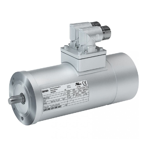
- Page 1 BA 13.0008 − EN .5ôE Operating Instructions SDSGA Inverter−optimised asynchronous motors Buy: www.ValinOnline.com | Phone 844-385-3099 | Email: CustomerService@valin.com...
- Page 2 Please read these instructions before you start working! Follow the enclosed safety instructions. Document history Material No. Version Description 409413 03/1999 TD09 First edition for pilot series 409413 04/2001 TD09 Chapter 3.2: Extension of application conditions All chapters: Revised 452930 04/2002 TD09 Extended by chapter 5.2.1, type and quantity of lubricant...
- Page 3 Nameplates product series SDSLL Field Contents Example Manufacturer CE identification Type of current Motor type Date of manufacture Commission No. Rated power (W) Rated speed (1/ Rated voltage (V) Rated frequency (Hz) Rated current (A) Rated torque (mF) Type of protection (IP) Operating mode Thermal class Material No.
- Page 4 Type code LLL − Inverter−optimised three−phase AC motors Legend for SDLGL type code Product group Small drives Current type Three−phase AC Ventilation Self ventilation (cooling by convection and radiation) Design/housing Smooth housing and round Ribbed housing, round Machine type Asynchronous machine Built−on accessories Absolute value encoder Brake and sin/cos absolute value encoder or SSI absolute value encoder...
-
Page 5: Table Of Contents
Contents Preface and general information ..........About these Operating Instructions . -
Page 6: Preface And General Information
Terminology used Term In the following text used for Motor Inverter−optimised motor of type SDS Drive system Drive system with inverter−optimised motor of type SDS or other Lenze drive components 1.1.2 Scope of supply Short description ƒ After receipt of the delivery, check immediately whether the items delivered match the accompanying papers. -
Page 7: Legal Regulations
The process−related notes and circuit sections used in these instructions are suggestions whose suitability for the respective application must be checked. Lenze assumes no guarantee for the suitability of the listed procedures and circuit samples. These operating instructions describe the product features without guaranteeing them. -
Page 8: Safety Instructions
Safety instructions Personnel responsible for safety Safety instructions Personnel responsible for safety Operator An operator is any natural or legal person who uses the drive system or on behalf of ƒ whom the drive system is used. The operator or his safety officer must ensure ƒ... -
Page 9: Residual Hazards
Safety instructions Residual hazards Residual hazards Protection of persons The motor surfaces can become very hot. Danger of burns when touching! Install a guard, if necessary. High−frequency voltages can be capacitively transferred to the motor housing through the inverter supply. Carefully earth the motor housing. - Page 10 Safety instructions Safety instructions for low−voltage machinery 3. Transport, storage The forwarder must be informed directly after receipt of the goods about all damage or deficiencies; if necessary, commissioning must be stopped. Tighten screwed−in ring bolts before transport. They are designed for the weight of the low−voltage machine, do not apply extra loads.
- Page 11 Safety instructions Safety instructions for low−voltage machinery 6. Operation £ 3.5 mm/s (Pr £ 15 kW) or 4.5mm/s (Pr > 15 kW) are acceptable in Vibration severities v coupled mode operation. In case of deviations from normal operation, e.g. increased temperatures, noises, vibration, find the cause and, if necessary, contact the manufacturer.
-
Page 12: Definition Of Notes Used
7. Inverter−driven operation for asynchronous motors The indications in the terminal box inform about the limit values for the voltage that may be permanently applied to the insulation system of the motor. Example: SDSGA series. Permissible voltage: û v 1.5 kV... -
Page 13: Technical Data
The torques and weights indicated in Tab. 2 are guide values for the selection of the ƒ transmission elements and base. The rated data indicated on the nameplate refer to operation with Lenze servo ƒ inverters of the 9300 series with an inverter input voltage (mains voltage) of 400 V and an inverter frequency of 8 kHz. -
Page 14: Shaft Loads
Technical data Rated data Shaft loads 3.1.1 Shaft loads The permissible loads listed in the table (Tab. 2) are either radial forces or axial forces. KL−SDS−001 Fig. 1 Points of action of radial and axial loads Ref. to the nominal bearing Permissible axial load service life of 10,000 h Permissible radial load, acts on the middle of the shaft... -
Page 15: General Data And Operating Conditions
Technical data General data and operating conditions General data and operating conditions Field Values Conformity Low−Voltage Directive (73/23/EEC) Climatic conditions Average relative humidity 85 %, without condensation Permissible Non−ventilated or with integral −20 °C ... +40 °C Without power derating, above temperature range fan without brake or with +40 °C with power derating see... -
Page 16: Other Application Conditions
Technical data General data and operating conditions Other application conditions 3.2.1 Other application conditions Other application conditions require a power derating or torque reduction using the ƒ factors listed in table 2 and 3 (see below). Installation height Permissible continuous torque M 40 °C 1000 m perm cont... - Page 17 Technical data General data and operating conditions Other application conditions 3.2.1.1 Power derating Power derating for other application conditions Cooling air temperature °C Power derating kυ 1.00 0.95 0.90 0.83 0.77 Installation height amsl in m 1000 2000 3000 4000 5000 Power derating k 1.00...
-
Page 18: Mechanical Installation
Mechanical installation Transport, storage and installation Mechanical installation Transport, storage and installation Danger! Use appropriate means of transport or hoists: ƒ – Ensure safe fixing. Transport the motors free of vibrations. ƒ Avoid heavy shocks. ƒ Storage free of vibration ƒ... -
Page 19: Site
Mechanical installation Site Site Danger! Do not use in hazardous areas! The motors are designed for the following rated conditions: Ambient and cooling air temperatures up to +40 °C (in case of other temperatures ƒ see chapter 3.2.1). Installation height up to 1000 m amsl (in case of other installation heights see ƒ... -
Page 20: Electrical Installation
Electrical installation Electrical installation Danger! Electrical connection must only be carried out by qualified personnel! ƒ Connections must only be made when the equipment is de−energised! ƒ Danger through unintended starts or electric shocks. Stop! It must be ensured that the supply voltage corresponds to the voltage indicated on the nameplate. -
Page 21: Attachments
Electrical installation Attachments Attachments Danger! Ensure that the drives are disconnected from the power supply when working on them! Stop! Unload motors or secure load applied to the drive. ƒ Do not use hammers or other heavy tools for assembly or disassembly! ƒ... -
Page 22: Table Of Lubricants
Electrical installation Gearbox mounting Table of lubricants Worm gearbox type SSN SSN gearbox SSN40 gearbox M13.0142 SSN40GK−026 Fig. 2 Worm gearbox Solid shaft design with flange Solid shaft design without flange Hollow shaft design Stop! After the shaft seal (51) has been mounted, mount the worm. Ensure stability of the motor shaft end when pinning (50). - Page 23 Electrical installation Gearbox mounting Table of lubricants Planetary gearbox type SPL M13.0134 Fig. 3 Screw Screw Washer Washer Setscrew Key (not applicable for SPL42) Spring pin (for SPL42) Gearbox type / size Dimensions Flange size Dimension x in mm SPL42 −−−...
-
Page 24: Connection Plan For Sdsgall Inverter Motor
5.2.2 Connection plan for SDSGALL inverter motor Parameter settings for 9300 servo inverters Note! More detailed information on wiring according to EMC guidelines can be obtained from the Operating Instructions for Lenze 9300 servo inverters. Code Meaning Setting SDSGALL047−22 SDSGALL056−22 SDSGALL063−22... - Page 25 Electrical installation Gearbox mounting Parameter settings for 9300 servo inverters ... for absolute value encoder/incremental encoder and thermal contact Inverter motor Pin No. Connection name Connection to: Pin assignment Track B / + SIN Track A inverted / − COS Track A + 5 V Supply + 5V + 8V...
-
Page 26: Commissioning
Commissioning and operation Before switching on Commissioning Stop! Ensure that the drives are disconnected from the power supply when ƒ working on them! The drive must only be commissioned by qualified personnel! ƒ Do not use the drive in rooms exposed to explosion danger! ƒ... -
Page 27: During Operation
– impeded heat dissipation or deposits on the drive system and in the air ducts. In the event of faults, please see the table in chapter 8. If the fault cannot be ƒ eliminated, please contact the Lenze Service. BA 13.0008 − EN Buy: www.ValinOnline.com | Phone 844-385-3099 | Email: CustomerService@valin.com... -
Page 28: Maintenance/Repair
Maintenance/repair Temperature monitoring Maintenance/repair Danger! Ensure that no voltage is applied to the drive system while working on it! ƒ High temperatures of the motor surfaces. Observe cooling times! ƒ Unload motor or secure loads which are applied to the drive! ƒ... -
Page 29: Repair
Maintenance/repair Repair Repair It is recommended to have all repairs performed by Lenze Service. ƒ Delivery of spare parts is available upon request. ƒ BA 13.0008 − EN Buy: www.ValinOnline.com | Phone 844-385-3099 | Email: CustomerService@valin.com... -
Page 30: Troubleshooting And Fault Elimination
– Please observe the corresponding chapters in the Operating Instructions for the other components of the drive system. If the fault cannot be eliminated by one of the measures listed in these Operating ƒ Instructions, please contact the Lenze Service. Fault Cause Remedy...
Need help?
Do you have a question about the SDSGA and is the answer not in the manual?
Questions and answers