Lenze MCS09 Mounting And Switch-On Instructions
Geared servo motors
Hide thumbs
Also See for MCS09:
- Operating instructions manual (56 pages) ,
- Operating instructions manual (46 pages)

Related Manuals for Lenze MCS09


Summary of Contents for Lenze MCS09
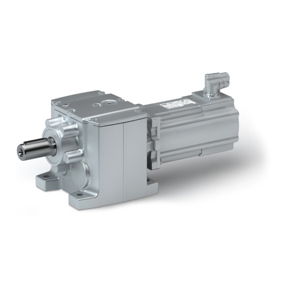
- Page 1 Mounting and switch-on instructions EN Geared servo motors g500-H / MCS helical geared servo motor...
-
Page 3: Table Of Contents
Contents Contents About this document Document description Further documents Notations and conventions Safety instructions Basic safety instructions Application as directed Residual hazards Product information Identification of the products Nameplates Product codes Equipment Transport Storage Mechanical installation Important notes Preparation Installation Mounting positions Ventilation Dimensions... - Page 4 Contents Technical data Standards and operating conditions Conformities and approvals Protection of persons and device protection EMC data Environmental conditions Motor data Rated data Inverter power supply 400 V, self-ventilated motors Inverter power supply 400 V, forced ventilated motors Inverter power supply 230 V, self-ventilated motors Environmental notes and recycling...
-
Page 5: About This Document
The documentation must always be complete and in a perfectly readable state. • Further documents Information and tools with regard to the Lenze products can be found on the Internet: www.Lenze.com à Downloads... -
Page 6: Notations And Conventions
About this document Notations and conventions Notations and conventions Conventions are used in this document to distinguish between different types of information. Numeric notation Decimal separator Point Generally shown as a decimal point. Example: 1 234.56 Warnings UL Warnings Are used in English and French. UR warnings Text Engineering Tools... -
Page 7: Safety Instructions
Safety instructions Basic safety instructions Safety instructions Basic safety instructions Disregarding the following basic safety instructions and safety information may lead to severe personal injury and damage to property! Only use the product as directed. • Never commission the product in the event of visible damage. •... -
Page 8: Residual Hazards
Safety instructions Residual hazards Residual hazards Even if notes given are taken into consideration and protective measures are implemented, the occurrence of residual risks cannot be fully prevented. The user must take the residual hazards mentioned into consideration in the risk assessment for his/her machine/system. - Page 9 Safety instructions Residual hazards Gearbox protection Excessive vibration accelerations and resonances will damage the gearbox. • Do not operate the gearbox at vibration accelerations > 2 g (20 m/s ) of the machine. Do not operate the gearbox in the resonance range of the machine. Excessive torques will damage the gearboxes.
-
Page 10: Product Information
Product information Identification of the products Nameplates Product information Identification of the products Nameplates The nameplate is attached to the motor. 10.1 10.2 10.3 10.4 11.1 11.2 11.3 12.1 12.2 12.3 Pos. Contents Pos. Contents Manufacturer/production location Encoder type designation Motor type/standard Brake data Gearbox type... -
Page 11: Product Codes
Product information Identification of the products Product codes Product codes Gearbox product code Example Product type Gearboxes Product family Generation Gearbox type Helical gearbox Output torque 45 Nm 100 Nm 140 Nm 210 Nm 320 Nm 450 Nm 600 Nm 850 Nm 1500 Nm 3000 Nm... - Page 12 Product information Identification of the products Product codes Product code of MCS synchronous servo motor Example Meaning Variant Product code Product family Motor Type Compact servo motors Version Synchronous Motor frame size Square dimension 62 mm Square dimension 89 mm Square dimension 116 mm Square dimension 142 mm Square dimension 192 mm...
- Page 13 Product information Identification of the products Product codes Product code feedbacks Example 1024 Meaning Variant Product code Product family Resolver Resolver for safety function Incremental encoder Incremental encoder with commutation signal Absolute value encoder, singleturn Absolute value encoder, multiturn Number 2-pole Resolver for servo motors 2-pole Resolver for three-phase AC motors...
-
Page 14: Equipment
Product information Equipment Equipment The following figure provides an overview of the elements and connections on the product. Their position, size and appearance may vary. Ventilation Temperature monitoring (depending on the mounting position) Oil filler plug Motor connection (depending on the mounting position) Oil level check (depending on the mounting position) Cooling... -
Page 15: Transport
Transport Transport Ensure appropriate handling. • Make sure that all component parts are securely mounted. Secure or remove loose • component parts. Only use safely fixed transport aids (e.g., eye bolts or support plates). • Do not damage any components during transport. •... - Page 16 Transport Position of the eye bolt G50AH045 ... G50BH114 G50BH121 ... G50BH230 Thread Load carrying 1200 1800 capacity...
-
Page 17: Storage
Storage Storage Storage up to one year: Observe the climatic conditions according to the technical data • 4Environmental conditions ^ 50 Store in a dry, low-vibration environment (V < 0.2 mm/s) without aggressive atmosphere • in the interior Protect from dust, shocks and sunlight •... -
Page 18: Mechanical Installation
Ambient media − especially chemically aggressive ones − may damage shaft sealing rings, • lacquers and plastics. Lenze offers special surface and corrosion protection in this case. • Only install the gearbox in the mounting position shown. •... -
Page 19: Installation
Mechanical installation Installation Mounting positions Installation The mounting surfaces must be plane, torsionally rigid and free from vibrations. • The mounting areas must be suited to absorb the forces and torques generated during • operation. Ensure an unhindered ventilation. • For versions with a fan, keep a minimum distance of 10 % from the outside diameter of the •... -
Page 20: Ventilation
Mechanical installation Installation Ventilation Ventilation No ventilation is required for the gearboxes G50AH045 …BH121. The gearbox G50BH121 can optionally be fitted with ventilation units. From G50BH132onwards, the gearboxes are supplied with ventilation units as standard. Gearboxes that are delivered with a ventilation unit are provided with a label. Remove the transport locking device on the vent valve before initial commissioning. - Page 21 Mechanical installation Installation Ventilation Mounting position M4 (C) Mounting position M5 (F) Mounting position M6 (E) Filling and ventilation Control ① ② Drain G50BH121 ① G50BH132 ② G50BH145...
- Page 22 Mechanical installation Installation Ventilation G50BH160 ... BH230 Mounting position M1 (A) Mounting position M2 (D) Mounting position M3 (B) Filling and ventilation Check Drain...
- Page 23 Mechanical installation Installation Ventilation Mounting position M4 (C) Mounting position M5 (F) Mounting position M6 (E) Filling and ventilation Control Drain Gearbox with oil compensation reservoir for mounting position M4 (C) In order to guarantee a reliable lubrication of the toothed parts in mounting position M4 (C) (motor is on the gearbox vertical from the top), a high filling level is required in the gearbox.
-
Page 24: Dimensions
Mechanical installation Dimensions Dimensions Dimensions are contained in the configuration document. Mounting Transmission elements Fit or remove transmission elements only using suitable equipment. • For fitting the transmission elements use the center hole in the shaft. • Avoid impacts and shocks. •... -
Page 25: Electrical Installation
Use of filters, chokes • Use of special motor cables • Preparation The notes for the electrical connection can be found in the enclosed mounting instructions. EMC-compliant wiring The EMC-compliant wiring is described in detail in the documentation of the Lenze inverters. -
Page 26: Motor Connection
9.5 mm > 178 mm Cable glands The bore holes for the cable glands M25, M20 and M32 are located on both sides and closed. They can be opened according to need. Motor MCS09 MCS14L15 MCS14L32 MCS12 MCS14P14 MCS14P32 MCS14H... - Page 27 Electrical installation Motor connection Connection via terminal box Position of the connections Position Meaning Power connection Brake connection Feedback connection Connection of temperature monitoring PE connection Large area shield contact. Terminal box, power Contact Name Meaning Motor winding phase PE conductor Terminal box, DC brake Contact Name...
- Page 28 Electrical installation Motor connection Connection via terminal box Terminal box, SinCos absolute value encoder with Hiperface Contact Name Meaning + UB Supply + Mass Track A / + COS A¯ Track A inverse / - COS Track B / +SIN B¯...
-
Page 29: Connection Via Icn Connector
One Cable Technology (OCT): Power connection, brake, feedback and temperature monitoring Motor Connector Motor Connector Motor Connector Motor Connector MCS06... ICN-M23 MCS14H15- ICN-M23 MCS14P14- ICN-M23 MCS19J14- ICN-M23 MCS09... ICN-M23 MCS14H28- ICN-M40 MCS14P26- ICN-M40 MCS19J29- ICN-M40 MCS12... ICN-M23 MCS14H32- ICN-M23 MCS14P32- ICN-M40 MCS19J30- ICN-M40 MCS14D14-... - Page 30 Electrical installation Motor connection Connection via ICN connector Standard connection Connection of power and brake ICN-M23 connector assignment 6-pole ICN M23 6-pole Contact Name Meaning PE conductor Brake DC +/AC Brake DC -/AC Power phase U Power phase V Power phase W ICN-M40 connector assignment 8-pole ICN M40 8-pole...
- Page 31 Electrical installation Motor connection Connection via ICN connector Feedback and temperature monitoring connection ICN-M23 connector assignment Resolver Code 0° ICN M23 for resolvers Contact Name Meaning +Ref Transformer windings -Ref Transformer windings Supply: Electronic nameplate (Only for motors and inverters that support +VCC ETS this function) +COS...
- Page 32 Electrical installation Motor connection Connection via ICN connector ICN-M23 connector assignment SinCos absolute value encoder with EnDat interface Code 0° ICN M23 SinCos absolute value encoder with EnDat Contact Name Meaning UP Sensor Up Sensor Not assigned Not assigned 0 V Sensor 0 V sensor PT1000/KTY temperature sensor PT1000/KTY temperature sensor...
- Page 33 Electrical installation Motor connection Connection via ICN connector One Cable Technology (OCT) Connection of power, brake, feedback and temperature monitoring ICN-M23 connector assignment, hybrid For One Cable Technology (OCT) with digital absolute value encoder ICN M23 Hybrid for One Cable Technology (OCT) with digital absolute value encoder Contact Name Meaning...
- Page 34 Electrical installation Motor connection Connection via ICN connector ICN-M40 connector assignment, hybrid For One Cable Technology (OCT) with digital absolute value encoder DSL1 DSL2 ICN M40 Hybrid for One Cable Technology (OCT) with digital absolute value encoder Contact Name Meaning Power phase U Power phase V Power phase W...
- Page 35 Electrical installation Motor connection Connection via ICN connector Assembly of ICN connectors NOTICE Live cables! Possible destruction of the connector. ▶ Never remove connector when voltage is being applied! ▶ Disable inverter before removing the connector! NOTICE Loss of the protection class due to incorrect mounting! Malfunctions may occur.
-
Page 36: Commissioning
Commissioning Important notes Commissioning Important notes NOTICE Do not brake the motor by short-circuit operation. Short-circuit braking may damage the motor. Before initial switch-on That the drive does not show any visible signs of damage. • Is the mechanical fixing o.k.? •... -
Page 37: Functional Test
Commissioning Functional test Functional test After commissioning, check all individual functions of the drive: Rotating direction in decoupled state • Torque behavior and current consumption • Function of the feedback system • Brake function • During operation, carry out inspections on a regular basis. Pay special attention to: Unusual noises •... -
Page 38: Maintenance
Regulations 2008] . Any work on the safety encoder which has not been executed professionally will cause a loss of the safety functions. ▶ The safety encoder may only be repaired or replaced by the Lenze service or its authorised persons. -
Page 39: Maintenance Intervals
Maintenance Maintenance intervals Maintenance intervals Geared motor/gearbox Time interval Measures Description of the operations After assembly and after 3 hours , check fastening. Check all fixing screws on the gearbox (foot, flange and shrink disc fixing ...) for tightness. On the first day, then every General check Pay attention to unusual operating noises, vibrations and impermissibly high month... - Page 40 Maintenance Maintenance intervals Determine change intervals for lubricants 1. Measure the lubricant temperature at the drain plug 2. Add 10 C 3. Determined the change interval from the diagram Position Of the drain plug 4Ventilation ^ 20 1000 50000 10000 Oil sump temperature [°C] Synthetic oil: CLP HC/CLP PG Change interval in operating hours [h]...
-
Page 41: Maintenance Work
Maintenance Maintenance work Maintenance work Check the oil level NOTICE ▶ Check the oil level in cold condition! Check the oil level by means of the displayed dipsticks. Depending on the gearbox type and the mounting position (M1 ... M6), make these according to the following templates. The gearbox type and mounting position are indicated on the nameplate. - Page 42 Maintenance Maintenance work Gearbox G50BH121 ... H145 Template: Dipsticks for G50BH121...
- Page 43 Maintenance Maintenance work Template: Dipsticks for G50BH132...
- Page 44 Maintenance Maintenance work Template: Dipsticks for G50BH145 How to check the lubricant level: 1. Remove the control screw at the marked position.4Ventilation ^ 20 2. Insert the dipstick through the threaded hole. Observe the position of the dipstick in the template! 3.
- Page 45 Maintenance Maintenance work Gearbox G50BH160 ... G50BH314 How to check the lubricant level: 1. Remove the control screw at the marked position.4Ventilation ^ 20 2. Insert auxiliary tool through the threaded hole. 3. Carefully pull out the auxiliary tool and determine the lubricant level. The lubricant level may be between the threaded hole and dimension "x".
- Page 46 Maintenance Maintenance work Tightening torques for venting elements and screw plugs Threaded hole Tightening torque M10 x 1 M12 x 1.5 M16 x 1.5 M20 x 1.5 Change roller bearing lubricant Recommended lubricants: Ambient temperature Manufacturer Type Gearbox roller bearing −30 °C ...
-
Page 47: Repair
First check the possible causes of malfunction according to the 4Diagnostics and fault • elimination ^ 48 If the fault cannot be remedied using one of the measures listed, please contact the Lenze • service department. The contact data can be found on the rear of this documentation. -
Page 48: Diagnostics And Fault Elimination
If faults occur during the operation of the drive, the table below helps you to identify the causes. If it is not possible to remedy the fault using the measures listed, please contact the Lenze service department. Error Possible cause... -
Page 49: Technical Data
Technical data Standards and operating conditions Conformities and approvals Technical data Standards and operating conditions Conformities and approvals More information and certificates of approval can be found under g500 + MCS helical geared motors Europa Country Conformity/approval Product representation European Union CE mark Eurasian Economic Union (EAEU) EAC mark... -
Page 50: Environmental Conditions
Technical data Standards and operating conditions Environmental conditions Environmental conditions Climate 1K3 (-20 ... +40 °C) >3 months Storage EN 60721-3-1:1997 1K3 (-20 ... +60 °C) <3 months Transport EN 60721-3-2:1997 2K3 (-20 ... +70 °C) 3K3 (-10 ... +40 °C) Operation, without brake EN 60721-3-3:1995 + Operation... -
Page 51: Motor Data
Technical data Motor data Rated data Motor data Rated data Inverter power supply 400 V, self-ventilated motors Motor MCS06C60- MCS06C41- MCS06F60- MCS06F41- MCS06I60- MCS06I41- Standstill torque 0.800 0.800 1.50 1.50 2.00 2.00 Rated torque 0.500 0.600 0.900 1.20 1.20 1.50 rated Max. - Page 52 Technical data Motor data Rated data Motor MCS09D60- MCS09D41- MCS09F60- MCS09H60- MCS09F38- MCS09L51- Standstill torque 3.30 3.30 4.20 5.50 4.20 7.50 Rated torque 1.80 2.30 2.40 3.00 3.10 3.60 rated Max. torque 9.50 9.50 15.0 20.0 15.0 32.0 Rated speed 6000 4050 6000...
- Page 53 Technical data Motor data Rated data Motor MCS09H41- MCS09L41- MCS12D41- MCS12D20- MCS12H35- MCS12H15- Standstill torque 5.50 7.50 6.40 6.40 11.4 11.4 Rated torque 3.80 4.50 4.30 5.50 7.50 10.0 rated Max. torque 20.0 32.0 18.0 18.0 29.0 29.0 Rated speed 4050 4050 4050...
- Page 54 Technical data Motor data Rated data Motor MCS12L41- MCS12L20- MCS14D36- MCS14D15- MCS14H32- MCS14H15- Standstill torque 15.0 15.0 11.0 11.0 21.0 21.0 Rated torque 11.0 13.5 7.50 9.20 14.0 16.0 rated Max. torque 56.0 56.0 29.0 29.0 55.0 55.0 Rated speed 4050 1950 3600...
- Page 55 Technical data Motor data Rated data Motor MCS14L32- MCS14P32- MCS14L15- MCS14P14- MCS19F30- MCS19F14- Standstill torque 28.0 37.0 28.0 37.0 32.0 32.0 Rated torque 17.2 21.0 23.0 30.0 21.0 27.0 rated Max. torque 77.0 77.0 86.0 86.0 Rated speed 3225 3225 1500 1350 3000...
- Page 56 Technical data Motor data Rated data Motor MCS19J30- MCS19P30- MCS19J14- MCS19P14- Standstill torque 51.0 64.0 51.0 64.0 Rated torque 29.0 32.0 40.0 51.0 rated Max. torque Rated speed 3000 3000 1425 1350 rated Max. speed 4000 4000 4000 4000 Rated power rated Standstill current 30.5...
-
Page 57: Inverter Power Supply 400 V, Forced Ventilated Motors
Technical data Motor data Rated data Inverter power supply 400 V, forced ventilated motors Motor MCS12H34- MCS12H14- MCS12L39- MCS12L17- MCS12D35- MCS12D17- Standstill torque 12.8 12.8 19.0 19.0 7.50 7.50 Rated torque 10.5 12.0 14.0 17.0 6.00 7.00 rated Max. torque 29.0 29.0 56.4... - Page 58 Technical data Motor data Rated data Motor MCS14D30- MCS14D14- MCS14H28- MCS14H12- MCS14L30- MCS14L14- Standstill torque 12.5 12.5 25.5 25.5 34.5 34.5 Rated torque 10.5 12.0 20.5 23.5 25.5 30.5 rated Max. torque 29.0 29.0 54.8 54.8 77.1 77.1 Rated speed 3000 1350 2775...
- Page 59 Technical data Motor data Rated data Motor MCS14P26- MCS14P11- MCS19F29- MCS19F12- MCS19J29- MCS19P29- Standstill torque 43.5 43.5 41.5 41.5 70.5 86.0 Rated torque 33.0 42.0 32.5 38.0 50.5 53.0 rated Max. torque 86.0 86.0 Rated speed 2625 1050 2850 1200 2850 2850 rated...
- Page 60 Technical data Motor data Rated data Motor MCS19J12- MCS19P12- Standstill torque 70.5 86.0 Rated torque 62.5 72.0 rated Max. torque Rated speed 1200 1200 rated Max. speed 4000 4000 Rated power rated Standstill current 20.3 22.4 Rated current 18.3 21.3 rated Max.
-
Page 61: Inverter Power Supply 230 V, Self-Ventilated Motors
Technical data Motor data Rated data Inverter power supply 230 V, self-ventilated motors Motor MCS06C60L MCS06C41L MCS06F60L MCS06F41L MCS06I60L MCS06I41L Standstill torque 0.800 0.800 1.50 1.50 2.00 2.00 Rated torque 0.500 0.600 0.900 1.20 1.20 1.50 rated Max. torque 2.40 2.40 4.40 4.40... - Page 62 Technical data Motor data Rated data Motor MCS09D60L MCS09D41L MCS09F60L MCS09H60L MCS09F38L MCS09H41L Standstill torque 3.30 3.30 4.20 5.50 4.20 5.50 Rated torque 1.80 2.30 2.40 3.00 3.10 3.80 rated Max. torque 9.50 9.50 15.0 20.0 15.0 20.0 Rated speed 6000 4050 6000...
- Page 63 Technical data Motor data Rated data Motor MCS09L41L MCS12H15L MCS12L20L MCS12D41L MCS12D20L MCS12H30L Standstill torque 7.50 11.4 15.0 6.40 6.40 11.4 Rated torque 4.50 10.0 13.5 4.30 5.50 8.00 rated Max. torque 32.0 29.0 56.0 18.0 18.0 29.0 Rated speed 4050 1500 1950...
-
Page 64: Environmental Notes And Recycling
Lenze products and their packaging: Lenze products are partly subject to the EU Directive on the restriction of certain hazardous substances in electrical and electronic equipment 2011/65/EU: RoHS Directive [UKCA: S.I. 2012/3032 - The Restriction of the Use of Certain Hazardous Substances in Electrical and Electronic Equipment Regulations 2012] . - Page 68 Lenze SE Postfach 101352 · 31763 Hameln Hans-Lenze-Straße 1 · 31855 Aerzen GERMANY Hannover HRB 204803 Phone +49 5154 82-0 Fax +49 5154 82-2800 sales.de@lenze.com www.Lenze.com © 03/2022 · · 1.0 · www.Lenze.com...
Need help?
Do you have a question about the MCS09 and is the answer not in the manual?
Questions and answers