Lenze MQA Series Project Planning
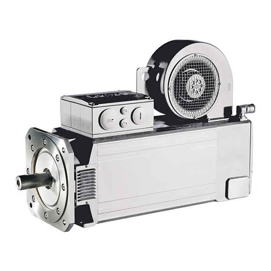
Asynchronous servo motor
Hide thumbs
Also See for MQA Series:
- Operating instructions manual (46 pages) ,
- Mounting instructions (37 pages) ,
- Mounting and switch-on instructions (64 pages)
Table of Contents
Advertisement
Quick Links
Advertisement
Table of Contents

Subscribe to Our Youtube Channel
Related Manuals for Lenze MQA Series


Summary of Contents for Lenze MQA Series
- Page 1 Project planning EN Servo motors MQA asynchronous servo motor...
-
Page 3: Table Of Contents
Contents Contents About this document Document description Further documents Notations and conventions Product information Product description Identification of the products Features The modular system Information on project planning Safety instructions Basic safety instructions Application as directed Foreseeable misuse Residual hazards Drive dimensioning Final configuration Surface and corrosion protection... - Page 4 Contents Product extensions Motor connection Connection via terminal box Connection via ICN connector Brakes Spring-applied brakes Feedback Resolver Incremental encoder Absolute value encoder Blower Temperature monitoring Thermal detectors PT1000 Product codes Environmental notes and recycling Appendix Good to know Approvals and directives Operating modes of the motor Enclosures...
-
Page 5: About This Document
The documentation must always be complete and in a perfectly readable state. • Further documents Information and tools with regard to the Lenze products can be found on the Internet: www.Lenze.com à Downloads... -
Page 6: Notations And Conventions
About this document Notations and conventions Notations and conventions Conventions are used in this document to distinguish between different types of information. Numeric notation Decimal separator Point Generally shown as a decimal point. Example: 1 234.56 Warnings UL Warnings Are used in English and French. UR warnings Text Engineering Tools... -
Page 7: Product Information
Product information Product description Product information Product description The MQA asynchronous servo motor for precisely controlled motion. The naturally ventilated MQA asynchronous servo motor is suitable for applications that require a high dynamic performance, high construction-related operational reliability and precisely controlled motion. In connection with the i700 and i950 servo inverters, Servo Drives 9400, and Inverter Drives 8400 TopLine, high-performance drive solutions in the torque range from 66 to 1100 Nm can be obtained. -
Page 8: Features
Product information Features Features Motor connection Cooling Power Brake Motor connection Feedback Temperature monitoring Output flange Feedback Output shaft Brake Temperature monitoring... -
Page 9: The Modular System
Product information The modular system The modular system Values printed in bold are standard designs. Values that are not printed in bold are potential extensions, some of them including a surcharge. Motor MQA20 MQA22 MQA26 Technical data Rated power 10.6 ... 20.3 11.5 ... -
Page 10: Information On Project Planning
Information on project planning Safety instructions Information on project planning Safety instructions Disregarding the following basic safety measures and safety information may lead to severe personal injury and damage to property! Observe all specifications of the corresponding documentation supplied. This is the precondition for safe and trouble-free operation and for obtaining the product features specified. -
Page 11: Basic Safety Instructions
The procedural notes and circuit details described are only proposals. It is up to the user to check whether they can be adapted to the particular applications. Lenze does not take any responsibility for the suitability of the procedures and circuit proposals described. -
Page 12: Application As Directed
Information on project planning Safety instructions Application as directed Application as directed NOTICE Please observe the notes in the following chapters! ▶ Safety instructions ^ 10 ▶ Information on mechanical installation ^ 21 ▶ Information on electrical installation ^ 22 The product must only be actuated under the operating conditions and power limits •... -
Page 13: Residual Hazards
Information on project planning Safety instructions Residual hazards Residual hazards Even if notes given are taken into consideration and protective measures are implemented, the occurrence of residual risks cannot be fully prevented. The user must take the residual hazards mentioned into consideration in the risk assessment for his/her machine/system. - Page 14 Information on project planning Safety instructions Residual hazards Motor protection Version with plug: • Never disconnect the plug when energized. The plug could be destroyed. Switch off the voltage supply or disable the inverter prior to disconnecting the plug. Installed thermal detectors are no full protection for the machine. •...
-
Page 15: Drive Dimensioning
With the «Drive Solution Designer«, you can design the drive both quickly and to a high quality. The software contains profound and proven expertise with regard to drive applications and mechatronic drive components. Please get in touch with your Lenze representative. The dimensioning is suitable for: kinematic profiles •... - Page 16 Information on project planning Drive dimensioning Operation chart S1 operation S2,S3 and S6 operation Speed profiles Check operating conditions Define required input variables Determine correction factor Operating modes and operating time Operating modes and operating time Ambient temperature and installation height Ambient temperature and installation height Ambient temperature and installation height Determine motor on the basis of the forces acting...
- Page 17 Information on project planning Drive dimensioning Determine correction factor Operating modes S1, S2, S3, S6, and operating time Operating mode S1 Operating mode S2 Operating mode S3 Operating mode S6 1.4 - 1.5 1.4 - 1.5 1.5 - 1.6 1.15 - 1.2 1.3 - 1.4 1.4 - 1.5 1.07 - 1.1...
- Page 18 Information on project planning Drive dimensioning Operating modes S2, S3, and S6 Check and select servo motor/inverter combination Check Selection Unit Output torque ≥ M / ( k rated rated Output speed (recommendation) ≥ n rated rated Max. output torque. ≥...
- Page 19 Information on project planning Drive dimensioning Check and select servo motor/inverter combination Check Preselection Unit > M Output torque rated rated ≥ n Output speed rated rated Load-matching factor Requirement k = 0.5 ... 10 for an optimum dynamic performance/ / (J control properties Optimum k...
-
Page 20: Final Configuration
Information on project planning Final configuration Surface and corrosion protection Final configuration Check Connection dimensions Output shaft Output flange Product extensions Motor connection (connector/terminal box) Brake Feedback Blower More information about the final configuration: 4The modular system 4Product extensions ^ 50 Surface and corrosion protection Depending on the ambient conditions, the surface and corrosion protection system (called OKS) offers solutions for optimum protection. -
Page 21: Information On Mechanical Installation
Ambient media − especially chemically aggressive ones − may damage shaft sealing rings, • lacquers and plastics. Lenze offers special surface and corrosion protection in this case. • NOTICE Bearing damage caused by unbalance! Shafts with keyway are balanced with a half featherkey! ▶... -
Page 22: Information On Electrical Installation
The manufacturer of the system or machine is responsible for adherence to the limits • required in connection with EMC legislation. Preparation The notes for the electrical connection can be found in the enclosed mounting instructions. EMC-compliant wiring The EMC-compliant wiring is described in detail in the documentation of the Lenze inverters. -
Page 23: Technical Data
4 kHz. NOTICE In case of other operating conditions, the achievable values can differ for those mentioned. ▶ In case of extreme operating conditions, please get in touch with your Lenze representative. -
Page 24: Standards And Operating Conditions
Eurasian conformity: electromagnetic compatibility of technical means Approval cURus UL 1004-1 for USA and Canada (requirements of the CSA 22.2 No.100) UL 1004-6 Industrial Control Equipment, Lenze File No. E210321 UkrSepro for Ukraine Protection of persons and device protection Degree of protection IP23S EN 60034-5... -
Page 25: Radial Forces And Axial Forces
Technical data Radial forces and axial forces Radial forces and axial forces The values of the bearing service life L refer to an average motor speed of 3000 rpm. Depending on the ambient temperatures, they are also limited by the grease lifetime. - Page 26 Technical data Radial forces and axial forces Application of force at l Bearing service life L Motor MQA20 MQA22 MQA26 5000 h Radial force 3150 3500 6400 Axial tensile force -1170 -2240 -2080 ax, - Axial compression force 1600 1150 ax, + 10000 h Radial force...
-
Page 27: Rated Data
Technical data Rated data Inverter mains connection 400 V, Forced ventilated motors Rated data Inverter mains connection 400 V, Forced ventilated motors Product name MQA20L14H MQA20L29H MQA22P08H Standstill torque 76.0 76.0 Rated torque 71.3 66.2 Rated Max. torque max. Rated speed 1420 2930 Rated Max. - Page 28 Technical data Rated data Inverter mains connection 400 V, Forced ventilated motors Product name MQA26T05H MQA26T10H MQA26T12H Standstill torque Rated torque Rated Max. torque 1100 1100 1100 max. Rated speed 1030 1200 Rated Max. speed 5500 5500 5500 max. Rated power 17.0 31.1 35.4...
-
Page 29: Selection Tables
Technical data Selection tables Selection tables Notes on the selection tables The selection tables represent the combinations of servo motors and servo inverters. The serve as a rough overview. In the case of the servo inverters, the overload capacity depending on the switching frequency in the default setting is taken into consideration. - Page 30 8 kHz of the inverter. If the motors are operated at a lower switching frequency, please get in touch with your Lenze representative! When operating at 4 kHz, the motor generates just 95 % of its rated torque with increased noise emissions.
- Page 31 Technical data Selection tables MQA26, forced ventilated Motor Inverter E94A□□ E0474 E0594 E0864 E1044 E1454 E1724 E2024 E2454 E2924 E3664 MQA26T05H Standstill torque 268.0 268.0 325.0 Rated torque 268.0 268.0 296.0 rated Max. standstill torque 665.0 826.0 1100.0 0,max Max. torque 665.0 826.0 1100.0...
- Page 32 8 kHz of the inverter. If the motors are operated at a lower switching frequency, please get in touch with your Lenze representative! When operating at 4 kHz, the motor generates just 95 % of its rated torque with increased noise emissions.
- Page 33 Technical data Selection tables MQA26, forced ventilated Motor Inverter E84AVTC□ 1534 1834 2234 3034 3734 4534 MQA26T05H Standstill torque 325.0 325.0 325.0 325.0 Rated torque 295.2 295.2 295.2 295.2 rated Max. standstill torque 390.4 489.6 567.1 744.4 902.3 1080.2 0,max Max.
-
Page 34: Torque Characteristics
Torque characteristics Torque characteristics The torque/speed characteristic for your motor/inverter combination can be found on the Internet: http://www.lenze.com à Product Finder à M-n characteristics The following data apply to a mains voltage 3 x 400 V of the inverter. MQA20L14H (forced ventilated) - Page 35 Technical data Torque characteristics MQA22P08H (forced ventilated) MQA22P14H (forced ventilated)
- Page 36 Technical data Torque characteristics MQA22P17H (forced ventilated) MQA22P29H (forced ventilated)
- Page 37 Technical data Torque characteristics MQA26T05H (forced ventilated) MQA26T10H (forced ventilated)
- Page 38 Technical data Torque characteristics MQA26T12H (forced ventilated) MQA26T22H (forced ventilated)
-
Page 39: Dimensions
Technical data Dimensions Basic dimensions Dimensions Basic dimensions Notes on the basic dimensions Table content Explanation Total length without brake L Total length of the drive with resolver Total length with brake Total length of the drive with resolver Length of motor options Δ... - Page 40 Technical data Dimensions Basic dimensions MQA20, forced ventilated Design B3 Motor MQA20L14H MQA20L29H Total length without brake L Length of motor options Δ L mm Motor/connection distance AD mm...
- Page 41 Technical data Dimensions Basic dimensions MQA20, forced ventilated Design B3 Motor MQA20L14H MQA20L29H Total length without brake L Length of motor options Δ L mm Motor/connection distance AD mm...
- Page 42 Technical data Dimensions Basic dimensions MQA20, forced ventilated Design B35-FF215/265 Motor MQA20L14H MQA20L29H Total length without brake L Length of motor options Δ L mm Motor/connection distance AD mm...
- Page 43 Technical data Dimensions Basic dimensions MQA20, forced ventilated Design B35-FF215/265 Motor MQA20L14H MQA20L29H Total length without brake L Length of motor options Δ L mm Motor/connection distance AD mm...
- Page 44 Technical data Dimensions Basic dimensions MQA22, forced ventilated Design B3 Motor MQA22P08H MQA22P14H MQA22P17H MQA22P29H Total length without brake L Length of motor options Δ L mm Motor/connection distance AD mm...
- Page 45 Technical data Dimensions Basic dimensions MQA22, forced ventilated Design B35-FF265 Motor MQA22P08H MQA22P14H MQA22P17H MQA22P29H Total length without brake L Length of motor options Δ L mm Motor/connection distance AD mm...
- Page 46 Technical data Dimensions Basic dimensions MQA26, forced ventilated Design B3 Motor MQA26T05H MQA26T10H MQA26T12H MQA26T22H Total length without brake L Length of motor options Δ L mm Motor/connection distance AD mm...
- Page 47 Technical data Dimensions Basic dimensions MQA26, forced ventilated Design B35-FF350 Motor MQA26T05H MQA26T10H MQA26T12H MQA26T22H Total length without brake L Length of motor options Δ L mm Motor/connection distance AD mm...
-
Page 48: Additional Lengths
Technical data Dimensions Additional lengths Additional lengths The motor code indicates the short designation of the brake and feedback. Detailed information can be found for 4Product codes ^ 63 4Brakes ^ 54 4Feedback ^ 58 MQA20 Motor MQA20L14H MQA20L29H Cooling type Forced Forced Feedback (without brake B0) -
Page 49: Weights
Technical data Weights Additional weights Weights Additional weights Motors Motor MQA20 MQA22 MQA26 Spring-applied holding brake Standard braking 13.0 20.5 30.7 torque Increased braking 15.4 torque... -
Page 50: Product Extensions
Product extensions Motor connection Connection via terminal box Product extensions Motor connection Connection via terminal box If a motor is to be connected to an existing cable or plug connectors are not to be used for other reasons, the connection can also be made via a terminal box. The connection for feedback and temperature monitoring is generally via the ICN connector and the electric fan is connected via a terminal box. - Page 51 Product extensions Motor connection Connection via terminal box Cable glands The cut-outs for the cable glands are closed with sealing plugs. The cable glands are arranged on both sides with MQA20. The cable glands are arranged on one side with MQA22 and MQA26. If required, the terminal box can be rotated by 180 °...
-
Page 52: Connection Via Icn Connector
In order to provide for a quick and error-free connection of Lenze motors to Lenze inverters, we recommend using prefabricated Lenze system cables. - Page 53 Product extensions Motor connection Connection via ICN connector Feedback and temperature monitoring connection ICN-M23 connector assignment Resolvers Contact Name Meaning + Ref Code 0° Transformer windings - Ref Supply: Electronic nameplate +VCC ENP (Only for motors and inverters which support this function) + Cos Stator windings cosine...
-
Page 54: Brakes
If long motor supply cables are used, pay attention to the ohmic voltage drop along the cable and compensate for it with a higher voltage at the input end of the cable. The following applies to Lenze system cables: Resulting supply voltage ´... - Page 55 Product extensions Brakes To simplify matters, the friction energy per switching cycle can be calculated using the formula below and must not exceed the limit value for emergency stops, which depends on the switching rate: Friction energy Total mass inertia (motor + load) æ...
-
Page 56: Spring-Applied Brakes
Product extensions Brakes Spring-applied brakes Spring-applied brakes Rated data Engagement and disengagement times apply to rated voltage (± 0 %) and suppressor circuit of the brakes with a varistor with DC switching. Without a suppressor circuit, the times may be longer. The currents are the maximum values when the brake is cold (value used for dimensioning the current supply). - Page 57 Product extensions Brakes Spring-applied brakes Rated data with increased braking torque DC 24 V, motor code= F2 Motor MQA20L MQA22P Supply voltage range 21.6 ... 26.4 in,DC Rated voltage N,DC Rated torque At 20 °C At 120 °C Rated current 2.58 3.75 Engagement time...
-
Page 58: Feedback
Motors can perform speed-dependent safety functions for safe speed and/or safe relative position monitoring in a drive system by Lenze inverters or Controllers. In case of inverters, these functions are implemented by integrable safety modules and in case of Controllers by the additionally required Safety Controller. -
Page 59: Resolver
Product extensions Feedback Resolver Resolver The stator-supplied, 2-pole resolver with two stator windings shifted by 90 degrees and a rotor winding with a transformer winding can record both the speed and the rotor position, just like a single-turn absolute value encoder. The rotor position can be determined within one mechanical motor revolution after a voltage failure. -
Page 60: Incremental Encoder
Product extensions Feedback Incremental encoder Incremental encoder Incremental encoders can be used for speed measurement. Homing is required in order to enable positioning later. Feedback type TTL incremental SinCos incremental Feedback IG2048-5V-T IG4096-5V-T IG2048-5V-S IG1024-5V-V3 Motor code Speed-dependent safety functions Encoder type Single-turn Single-turn... -
Page 61: Blower
Product extensions Blower Blower The motors are cooled as a standard by means of a separate radial fan. The separate fans are optionally available with a dust filter. Rated data 50 Hz Motor MQA20L14H MQA22P08H MQA26T05H MQA20L29H MQA22P14H MQA26T10H MQA22P17H MQA26T12H MQA22P29H MQA26T22H... -
Page 62: Temperature Monitoring
Product extensions Temperature monitoring Thermal detectors PT1000 Temperature monitoring Thermal detectors PT1000 The thermal detector used continuously monitors the motor temperature. The temperature information is transferred to the inverter using the system cable of the feedback system. This is not a full motor protection! This makes it possible to determine the motor temperature in the permissible operating range with great accuracy. -
Page 63: Product Codes
Product codes Product codes Product code of MQA asynchronous servo motor Example Meaning Variant Product code Product family Motor Type Compact servo motors Variant Asynchronous Motor frame size Square dimension 200 mm Square dimension 220 mm Square dimension 260 mm Overall length Rated speed rpm x 100... -
Page 64: Environmental Notes And Recycling
Lenze products and their packaging: Lenze products are subject in part to EU Directive 2011/65/EU on the restriction of the use of certain hazardous substances in electrical and electronic devices (RoHS). This is documented accordingly in the EU Declaration of Conformity and with the CE mark. -
Page 65: Appendix
Appendix Good to know Approvals and directives Appendix Good to know Approvals and directives China Compulsory Certification documents the compliance with the legal product safety requirements of the PR of China - in accordance with Guobiao standards. CSA certificate, tested according to US and Canada standards Union Européenne documents the declaration of the manufacturer that EU Directives are complied with. -
Page 66: Operating Modes Of The Motor
Appendix Good to know Operating modes of the motor Operating modes of the motor Operating modes S1 ... S10 as specified by EN 60034-1 describe the basic stress of an electrical machine. In continuous operation a motor reaches its permissible temperature limit if it outputs the rated power dimensioned for continuous operation. -
Page 67: Enclosures
Appendix Good to know Enclosures Enclosures The degree of protection indicates the suitability of a motor for specific ambient conditions with regard to humidity as well as the protection against contact and the ingress of foreign particles. The degrees of protection are classified by EN 60529. The first code number after the code letters IP indicates the protection against the ingress of foreign particles and dust. - Page 68 © 09/2020 | | 2.0 Lenze Automation GmbH Postfach 101352, 31763 Hameln Hans-Lenze-Str. 1, 31855 Aerzen GERMANY HR Hannover B 205381 Phone +49 5154 82-0 Fax +49 5154 82-2800 sales.de@lenze.com www.Lenze.com...
Need help?
Do you have a question about the MQA Series and is the answer not in the manual?
Questions and answers