Table of Contents
Advertisement
Quality Assurance
Certificate Reg. No:
04 100 950420
Subject to change without notice
Manufacturing point: Jeddah, Saudi Arabia
Nearest port of embarkation: Jeddah Islamic port
Product classification: Commercial
Note: This manual discusses the Mechanical Installation of this unit, Start-up Procedures, Operating Sequences
and Service Instructions.
Read thoroughly the entire installation instruction manual before starting the unit installation, to get familiarized with
all steps and to identify if any additional reference materials as required.
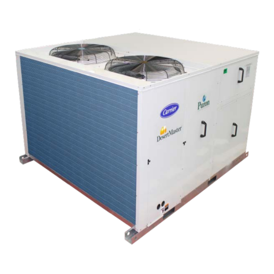
The 50TJM units are single side discharge rooftop cooling unit utilizing electric heat as an option. Units are pre-
wired, pre-charged with R-410A refrigerant, and tested at the factory. These units can be placed on the side of a
building or can be placed on a roof without roof curbs. Each unit is designed to occupy a minimal space. Piping and
drain connections are readily accessible.
For a complete list of options and accessories, refer to the Product Data Catalog.
Contact your local Carrier representative for additional reference materials.
50TJM
Nominal Cooling Capacity 15 - 28 Tons
HFC R - 410A Refrigerant
Page 1
Package Rooftop Units
Installation, Operation and Maintenance Instructions
Advertisement
Table of Contents

Related Manuals for Carrier DesertMaster 50TJM


Summary of Contents for Carrier DesertMaster 50TJM
- Page 1 Each unit is designed to occupy a minimal space. Piping and drain connections are readily accessible. For a complete list of options and accessories, refer to the Product Data Catalog. Contact your local Carrier representative for additional reference materials. Page 1...
-
Page 2: Table Of Contents
Table of Contents 1.0 – SAFETY CONSIDERATIONS ....................... 3 1.1 – General ..........................3 1.2 – Installation Safety Considerations ..................3 1.3 – Warranty ..........................3 Physical Data ............................5 Unit Dimensional Drawing......................6 – 7 2.0 – INSTALLATION ..........................8 2.1 –... -
Page 3: Safety Considerations
Warranty is based on the general terms and conditions of the manufacturer. Any modifications to the design and/or installation made without discussion with Carrier and without advance written agreement will result in the loss of the right to any warranty claims and any claim for injury to personnel as a result of these modifications. - Page 4 WARNING CAUTION ELECTRIC SHOCK HAZARD CUT HAZARD Failure to follow this warning could cause Failure to follow this warning could cause personal injury or death. personal injury. Before performing service or maintenance Sheet metal parts may have sharp edges or operations on unit, always turn off main burrs.
-
Page 5: Physical Data
Physical Data Table - 1 50TJM Unit Physical Data (50Hz) (English) Unit 50TJM Size Unit Dimensions Page - 9 Page - 10 Unit Operating Weight Page - 9 Page - 10 Refrigeration System 2 / Scroll Compressor No. / Type 50 / 50 Stage Of Capacity Control (%) Puron ®... -
Page 6: Unit Dimensional Drawing
UNIT DIMENSIONAL DRAWING: 50TJM - 18 and 50TJM - 24 (Fig - 1) SHIPPING DIMENSIONS (mm) CORNER WEIGHT (Kg) CENTER OF GRAVITY (mm) UNIT LENGTH WIDTH DEPTH TOTAL 50TJM - 18 2440 2235 1375 1050 1050 50TJM - 24 NOTES: 1. -
Page 7: Unit Dimensional Drawing
UNIT DIMENSIONAL DRAWING: 50TJM - 28 and 50TJM - 34 (Fig - 2) SHIPPING DIMENSIONS (mm) CORNER WEIGHT (Kg) CENTER OF GRAVITY (mm) UNIT LENGTH WIDTH DEPTH TOTAL 1125 50TJM - 28 3200 2485 1400 1350 1160 1150 50TJM - 34 NOTES: 1. -
Page 8: Installation
2 – INSTALLATION 2.1 – Jobsite Survey Complete the following checks before installation. 1. Consult local building codes or the U.S.A. National Electrical Code (Ref: ANSI/NFPA 70, [American National Standards Institute/National Fire Protection Association], latest revision) for special installation requirements. 2. -
Page 9: Positioning And Clearance
SHIPPING DIMENSIONS SHIPPING UNIT DIMENSIONS (mm) UNIT WEIGHT UNIT (mm) WEIGHT LENGTH WIDTH DEPTH GROSS (Kg) LENGTH WIDTH DEPTH NET(Kg) 50TJM - 18 2440 2235 1375 2440 2182 1348 50TJM - 24 2440 2235 1375 2440 2182 1348 50TJM - 28 3200 2485 1400... -
Page 10: Trap Condensate Drain
U.S.A standard ANSI/NFPA 70, National Electrical Code be followed. FIELD CONTROL WIRING – Install a Carrier approved accessory thermostat assembly according to the installation instructions included with the accessory. Locate thermostat assembly on a solid wall in the conditioned space to sense average temperature. -
Page 11: Electrical Data
Electrical Data Table - 3 50TJM Size 18 - 34 Compressor Electric Heater IFM Type MCA MOCP◊ Power No.1 No.2 Unit Size Min Voltage Supply Appl. 50TJM Voltage RLA LRA RLA LRA Qty HP FLA V / Ph / Hz 400 / 3 / 50 12.2 12.2... -
Page 12: Electrical Resistance Heater Data
Electric Resistance Heater Data - Table 4 HEATER kW HEATER FLA (PER STAGE) MINIMUM HEATING HEAT UNIT HEATER Unit Voltages Unit Voltages 50TJM STAGES STAGES 28kW 17.3 50/50 4800 2265 50/50 6000 2832 37kW 50/50 7000 3304 50/50 7000 3304 ACCESSORY HEATER PART NUMBER 400V UNIT... -
Page 13: Typical Wiring Schematic
Fig. - 6 Page 13... - Page 14 Fig. - 7 Page 14...
-
Page 15: Start-Up Instructions
3 – START-UP INSTRUCTIONS Use the following instructions and start-up checklist provided on the last page to check out the unit PRIOR to unit start-up. 3.1– Unit Preparation Check that unit has been installed in accordance with these installation instructions and all applicable codes. 3.2 –... -
Page 16: Condenser Fans And Motors
MOTOR PULLEY TURNS OPEN Unit Freq. 50TJM 1 1/2 2 1/2 3 1/2 4 1/2 5 1/2 1030 1001 1041 1011 50Hz 1041 1011 1029 Bold Fan RPM is Factory Setting Table 6 – Fan RPM at Motor Pulley Settings. 3.7–... -
Page 17: Evaporator Fan Performance Adjustment
CAUTION UNIT DAMAGE HAZARD Failure to follow this caution may result in damage to components. 1. The compressor is in a Puron® refrigerant system and uses a (POE) lubricant Emkarate RL 32 3MAF. In the field the oil level could be topped up with Mobil EAL Arctic 22 CC if 3MAF is not available. POE oil is extremely hygroscopic, meaning it absorbs water readily. -
Page 18: Belt Tension Adjustment
Fig. 9 Condenser - Fan Adjustment 4.7 – Refrigerant Charge Amount of refrigerant charge is listed on unit nameplate and in Table 1. Refer to Carrier GTAC II; Module 5; Charging, Recovery, Recycling, and Reclamation section for charging methods and procedures. Unit panels must be in place when unit is operating during charging procedure. -
Page 19: Control Circuit, 24-V
This control circuit is protected against over-current by a 3.2-amp circuit breaker. Breaker can be reset. If it trips, determine cause of trouble before resetting. 5.0 – REPLACEMENT PARTS A complete list of replacement parts may be obtained from any Carrier distributor. Page 19... -
Page 20: Fan Performance Table
6. Bold data shows the range of air flow rate for unit management system, other rpms require field-supplied drive. 7. Use of field-supplied motor may affect wiring size. Contact your Carrier representative for details. 8. Conversion - Bhp to KWI Bhp X 0.746... - Page 21 6. Bold data shows the range of air flow rate for unit management system, other rpms require field-supplied drive. 7. Use of field-supplied motor may affect wiring size. Contact your Carrier representative for details. 8. Conversion - Bhp to KWI Bhp X 0.746...
- Page 22 6. Bold data shows the range of air flow rate for unit management system, other rpms require field-supplied drive. 7. Use of field-supplied motor may affect wiring size. Contact your Carrier representative for details. 8. Conversion - Bhp to KWI Bhp X 0.746...
-
Page 23: Fan Performance Table
6. Bold data shows the range of air flow rate for unit management system, other rpms require field-supplied drive. 7. Use of field-supplied motor may affect wiring size. Contact your Carrier representative for details. 8. Conversion - Bhp to KWI Bhp X 0.746... -
Page 24: Cooling Chart
Cooling Chart CHARGING CHART 50TJM-18 Both Circuits All outdoor fans must be operating Add charge if above upper curve Reduce charge if below lower curve Liquid Pressure (PSIG) Fig - 10 Cooling Charging Charts for 50TJM Size 18 CHARGING CHART 50TJM-24 Both Circuits All outdoor fans must be operating Add charge if above upper curve... -
Page 25: Cooling Chart
Cooling Chart (cont) CHARGING CHART 50TJM-28 Both Circuits All outdoor fans must be operating Add charge if above upper curve Reduce charge if below lower curve Liquid Pressure (PSIG) Fig - 12 Cooling Charging Charts for 50TJM Size 28 CHARGING CHART 50TJM-34 Both Circuits All outdoor fans must be operating Add charge if above upper curve... -
Page 26: Troubleshooting
Troubleshooting Guide Table 8 — Cooling Service Analysis PROBLEM CAUSE REMEDY Compressor and condenser fan will not Power failure. Call power company. start. Fuse blown or circuit breaker tripped. Replace fuse or reset circuit breaker. Defective thermostat, contactor, transformer, or control Replace component. -
Page 27: Start-Up Checklist
START-UP CHECKLIST (Remove and Store in Job File) I. PRELIMINARY INFORMATION MODEL NO: DATE: SERIAL NO: TECHNICIAN: II. PRE-START-UP (Insert checkmark in box as each item is completed) 1) ALL PACKING MATERIALS HAVE BEEN REMOVED FROM THE UNIT. 2) VERIFY THAT UNIT INSTALLATION IS LEVEL. 3) CONDENSATE CONNECTION IS INSTALLED PER INSTALLATION INSTRUCTION. - Page 28 Manufacturer reserves the rights to discontinue, or change at any time, specifications or designs without notice and without incurring obligations Supersedes Version: 50TJM-IOM05 Version: 50TJM-IOM06 Page 28 Effective Date: 22-06-2013...
Need help?
Do you have a question about the DesertMaster 50TJM and is the answer not in the manual?
Questions and answers
Belt sizeS for 50TJM PACKAGE UNIT