Table of Contents
Advertisement
Copyright 2000 Carrier Corporation
Product
Data
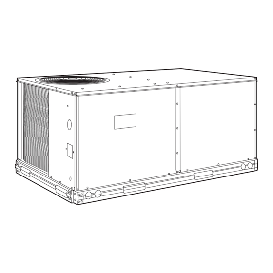
Single-Package Rooftop Units
with Electric Heat Option
Nominal Capacity: 17.6 kW to 35.9 kW
50TFF007
50TFF008-014
50TFF007-014
Electric Cooling
50 Hz
(5 to 10.2 Tons)
Single-Package Rooftop Units with:
• Galvanized pre-painted steel
cabinet
• Fifty-one mm (2-in.) return-air filters
• Commercial strength base rails
• Exclusive tool-less filter access
panel
• Corrosion-resistant sloped
condensate pan
• Single power entry to unit
• Commercial duty motors with
permanently lubricated bearings
• Standard cooling operation at
outdoor ambient temperatures as
low as –4 C (25 F)
• Meets ASHRAE Standard 62
(Indoor Air Quality)
Features/Benefits
Compact, vertical discharge
units convert to horizontal
discharge, combining
installation flexibility with
efficient performance and
easy maintenance.
Easy installation and
conversion
All units are shipped in the vertical dis-
charge configuration for fit-up to
standard roof curbs. (Two different curb
sizes fit unit sizes 007 and 008-014.)
The contractor can order and install the
roof curb early in the construction
stage, before decisions on size require-
ments are made.
All units feature roll-formed baserail
design with forklift slots on 3 sides and
rigging holes for easier maneuvering.
Durable packaging protects all units
during shipment and storage.
The units can be easily converted
from a vertical to a horizontal
discharge configuration by interchang-
ing the panels supplied with the unit.
Form 50TFF-C1PD
Advertisement
Table of Contents

Related Manuals for Carrier 50TFF007-014


Summary of Contents for Carrier 50TFF007-014
- Page 1 Durable packaging protects all units during shipment and storage. 50TFF008-014 The units can be easily converted from a vertical to a horizontal discharge configuration by interchang- ing the panels supplied with the unit. Copyright 2000 Carrier Corporation Form 50TFF-C1PD...
-
Page 2: Table Of Contents
Design techniques feature computer- and manufactured exclusively by tional field or factory-installed programmed balance between com- Carrier, the controls can be used to ac- EconoMi$er. This newly designed pressor, condenser, and evaporator. tively monitor and control all modes of EconoMi$er incorporates a... -
Page 3: Features/Benefits
Model number nomenclature LEGEND *Refer to 50TFF ordering data or contact your local Carrier representa- tive for 50TFF FIOP code table. — Aluminum †All coils have copper tubes. — Copper FIOP —... -
Page 4: Physical Data
*Evaporator coil fins/condenser coil fins. †Weight of 356 mm roof curb. — Aluminum — Brake Horsepower NOTE: The 50TFF007-014 units have a loss-of-charge/low-pressure BkW — Fan Input Watts x Motor Efficiency switch (accessory) located in the liquid line. — Copper... - Page 5 *Evaporator coil fins/condenser coil fins. †Requires the accessory/optional controls upgrade kit. — Aluminum — Brake Horsepower NOTE: The 50TFF007-014 units have a loss-of-charge/low-pressure BkW — Fan Input Watts x Motor Efficiency switch (accessory) located in the liquid line. — Copper...
-
Page 6: Options And Accessories
*Factory installed. †Field installed. HEAD PRESSURE CONTROL The 50TFF007-014 standard units are designed to operate in cooling at outdoor temperatures down to –3.8 C (25 F). With accessory Motormas- ter control (condenser fan speed modulation) or Motormaster II control (condenser fan cycling) units can operate at outdoor temperatures down to –17.8 C (0°... - Page 7 THERMOSTAT Zone thermostat (24 v) provides one- or 2-stage cooling for control of unit. Matching subbases are Carrier’s electronic programmable thermostat provides effi- available with or without tamperproof switches and cient temperature control by allowing you to program heating automatic changeover.
-
Page 8: Options And Accessories
ACCUSENSOR III SENSOR The Apollo direct digital controls are designed exclusively by Carrier, and are used to actively monitor and control all modes of operation as well as to monitor evaporator-fan status, filter status, supply-air temperature, outdoor-air temperature, and indoor-air quality. -
Page 9: Base Unit Dimensions
Base unit dimensions — 50TFF007 STD UNIT DURABLADE ECONOMI$ER “A” WEIGHT ECONWEIGHT WEIGHT CORNER WEIGHT CORNER WEIGHT CORNER WEIGHT CORNER WEIGHT UNIT PANEL LENGTH ″ [315.0] 50TFF007 213.2 15.4 21.3 67.1 46.7 70.3 29.0 1′-0 BOTTOM POWER CHART, THESE HOLES REQ’D FOR USE WITH ACCESSORY PACKAGES —... - Page 10 Base unit dimensions — 50TFF008-014 DURABLADE CORNER CORNER CORNER CORNER STD UNIT ECONOMI$ER ECONOMIZER WEIGHT WEIGHT WEIGHT WEIGHT “H” “J” “K” WEIGHT WEIGHT UNIT WEIGHT Ft-in. Ft-in. Ft-in. 50TFF008 1050 50TFF009 1013 1050 50TFF012 1253 50TFF014 1253 BOTTOM POWER CHART, THESE HOLES REQ’D CONNECTION SIZES FOR USE WITH ACCESSORY PACKAGES —...
-
Page 11: Accessory Dimensions
Accessory dimensions “E” “F” “G” CONNECTOR ROOF CURB UNIT SIZE “A” ALT DRAIN HOLE POWER CONTROL PKG. ACCY. ACCESSORY 50TFF ″ [19] NPT CRBTMPWR001A00 CRRFCURB001A00 1′-2″ [356] ″ ″ ″ [31.7] [19] NPT [12.7] CRRFCURB002A00 2′-0″ [610] CRBTMPWR002A00 ″ ″ 1′-9 1′-4″... - Page 12 Accessory dimensions (cont) “D” ALT CONNECTOR ROOF CURB UNIT SIZE “E” “F” “G” “A” “B” “C” DRAIN PACKAGE ACCESSORY 50TFF POWER CONTROL HOLE ACCESSORY CRRFCURB003A00 1′-2″ [356] ″ [19] NPT 008-014 ″ ″ [12.7] CRBTMPWR001A00 CRRFCURB004A00 2′-0″ [610] [19] NPT ″...
-
Page 13: Selection Procedure
Selection procedure (with 50TFF012 example) — SI I. Determine cooling and heating requirements IV. Determine fan speed and power require- at design conditions. ments at design conditions. Given: Before entering the Fan Performance tables, calcu- late the total static pressure required based on unit Required Cooling Capacity (TC) . -
Page 14: Selection Procedure
Selection procedure (with 50TFF012 example) — English I. Determine cooling and heating requirements IV. Determine fan speed and power require- at design conditions. ments at design conditions. Given: Before entering the Fan Performance tables, calcu- late the total static pressure required based on unit Required Cooling Capacity (TC) . -
Page 15: Performance Data
Performance data COOLING CAPACITIES — SI 50TFF007 (17.6 kW) Air Entering Evaporator — L/s/BF Temp (C) 700/0.05 950/0.07 1200/0.09 Air Entering Condenser Air Entering Evaporator — Ewb (C) (Edb) 15.8 17.7 19.6 21.5 16.8 18.7 20.7 22.6 17.4 19.3 21.3 23.3 15.8 15.5... -
Page 16: Performance Data
Performance data (cont) COOLING CAPACITIES — SI (cont) 50TFF008 (21.5 kW) Air Entering Evaporator — L/s BF Temp (C) 850/0.05 1130/0.075 Air Entering Condenser Air Entering Evaporator — Ewb (C) (Edb) 19.5 20.9 22.5 24.3 26.0 21.6 22.3 23.7 25.3 27.0 19.4 18.0... - Page 17 COOLING CAPACITIES — SI (cont) 50TFF009 (24.3 kW) Air Entering Evaporator — L/s/BF Temp (C) 1200/0.07 1400/.08 1700/0.11 Air Entering Condenser Air Entering Evaporator — Ewb (C) (Edb) 24.7 25.2 28.4 30.8 26.0 26.2 29.1 31.5 27.9 27.9 29.9 32.2 24.1 23.2 19.3...
- Page 18 Performance data (cont) COOLING CAPACITIES — SI (cont) 50TFF012 (29.2 kW) Air Entering Evaporator — L/s BF Temp (C) 1140/0.08 1520/0.105 Air Entering Condenser Air Entering Evaporator — Ewb (C) (Edb) 26.6 28.2 30.5 33.1 34.7 30.5 31.4 32.7 34.3 36.3 26.4 24.8...
- Page 19 COOLING CAPACITIES — SI (cont) 50TFF014 (35.9 kW) Air Entering Evaporator — L/s/BF Temp (C) 1500/0.13 2000/0.17 2350/0.21 Air Entering Condenser Air Entering Evaporator — Ewb (C) (Edb) 34.7 38.0 41.4 44.4 37.0 40.0 43.2 46.3 36.6 40.1 43.6 46.7 34.7 33.8 28.1...
- Page 20 Performance data (cont) COOLING CAPACITIES — ENGLISH 50TFF007 (5 TONS) Air Entering Evaporator — Cfm/BF Temp (F) 1500/0.05 2000/0.07 2500/0.09 Air Entering Condenser Air Entering Evaporator — Ewb (F) (Edb) 60.0 66.0 72.1 63.0 69.2 76.1 65.2 71.5 78.1 50.5 42.6 34.5 58.2...
- Page 21 COOLING CAPACITIES — ENGLISH (cont) 50TFF012 (8.3 TONS) Air Entering Evaporator — Cfm/BF Temp (F) 2500/0.09 3200/0.105 3800/0.12 4000/0.13 Air Entering Condenser Air Entering Evaporator — Ewb (F) (Edb) 95.1 108.3 116.7 104.5 112.8 121.4 106.2 114.9 124.4 107.0 115.8 124.2 77.4 64.2...
- Page 22 30 or additional information. — Kilowatt Input to Motor 6. Use of a field-supplied motor may affect wire sizing. Contact your Carrier representative to verify. NOTES: 7. To convert kW to bkW: 1. Boldface indicates field-supplied drive required (see Note 3).
- Page 23 30 or additional information. — Kilowatt Input to Motor 6. Use of a field-supplied motor may affect wire sizing. Contact your Carrier representative to verify. NOTES: 7. To convert kW to bkW: 1. Boldface indicates field-supplied drive required (see Note 3).
- Page 24 30 or additional information. — Kilowatt Input to Motor 6. Use of a field-supplied motor may affect wire sizing. Contact your Carrier representative to verify. NOTES: 7. To convert kW to bkW: 1. Boldface indicates field-supplied drive required (see Note 3).
- Page 25 30 or additional information. — Kilowatt Input to Motor 6. Use of a field-supplied motor may affect wire sizing. Contact your Carrier representative to verify. NOTES: 7. To convert kW to bkW: 1. Boldface indicates field-supplied drive required (see Note 3).
- Page 26 Evaporator-Fan Motor Performance table on page 30 for additional information. — Brake Horsepower 6. Use of a field-supplied motor may affect wire sizing. Contact your Carrier Watts — Input Watts to Motor representative to verify. 7. To convert Watts to Bhp: NOTES: 1.
- Page 27 Evaporator-Fan Motor Performance table on page 30 for additional information. — Brake Horsepower 6. Use of a field-supplied motor may affect wire sizing. Contact your Carrier Watts — Input Watts to Motor representative to verify. 7. To convert Watts to Bhp: NOTES: 1.
- Page 28 Evaporator-Fan Motor Performance table on page 30 for additional information. — Brake Horsepower 6. Use of a field-supplied motor may affect wire sizing. Contact your Carrier Watts — Input Watts to Motor representative to verify. 7. To convert Watts to Bhp: NOTES: 1.
- Page 29 Evaporator-Fan Motor Performance table on page 30 for additional information. — Brake Horsepower 6. Use of a field-supplied motor may affect wire sizing. Contact your Carrier Watts — Input Watts to Motor representative to verify. 7. To convert Watts to Bhp: NOTES: 1.
- Page 30 Performance data (cont) EVAPORATOR-FAN MOTOR PERFORMANCE MAXIMUM MAXIMUM MAXIMUM UNIT UNIT RATED ACCEPTABLE ACCEPTABLE ACCEPTABLE MAXIMUM 50TFF VOLTAGE CONTINUOUS CONTINUOUS OPERATING AMP DRAW BkW* BHP* WATTS 1.79 2.40 2,120 1.79 2.40 2,120 1.79 2.40 2,120 1.79 2.40 2,120 2.76 3.70 3,313 LEGEND *Extensive motor and electrical testing on these units ensures that the...
- Page 31 DURABLADE ECONOMIZER BAROMETRIC RELIEF DAMPER CHARACTERISTICS — 50TFF007 DURABLADE ECONOMIZER BAROMETRIC RELIEF DAMPER CHARACTERISTICS — 50TFF008-014...
- Page 32 Performance data (cont) ECONOMI$ER POWER EXHAUST PERFORMANCE ECONOMI$ER BAROMETRIC FLOW (50TFF007) 0.25 2500 0.20 2000 2 FANS OPERATING 1500 0.15 1000 1 FAN OPERATING 0.10 0.05 STATIC PRESSURE (in. wg) 0.00 1000 1500 2000 SIZE 007 FLOW (CFM) SIZES 008-014 ECONOMI$ER POWER EXHAUST PERFORMANCE (50TFF008-014) 5000...
- Page 33 0.03 0.04 0.05 0.06 0.07 0.08 EconoMi$er — — — 0.125 0.18 0.27 0.34 0.40 — ELECTRIC HEATING CAPACITIES — 50TFF007-014 UNIT UNIT ELECTRICAL ACCESSORY PART NO. 50TFF CHARACTERISTICS 50DJ90– 0921 0941 400-3-50 0951 16.0* 0941 17.7* 0941, 0951 1681 11.5...
-
Page 34: Electrical Data
Electrical data 50TFF007-014 VOLTAGE COMPR MINIMUM UNIT ELECTRIC HEAT* POWER SUPPLY NOMINAL RANGE (ea) (ea) DISCONNECT UNIT VOLTAGE 50TFF Nominal (50 Hz) MOCP** kW† — — 18.4 18.4 13.8 18.4 72.0 (3 phase) 16.8 20.8 16.0 27.8 32.1 17.7 30.7 34.6... -
Page 35: Typical Piping And Wiring
Typical piping and wiring — 50TFF007-014 (sizes 008-014 shown) VERTICAL DISCHARGE DUCTING TOOL-LESS FILTER ACCESS DOOR CONDENSER-FAN DISCHARGE AIR HORIZONTAL DISCHARGE DUCTING LEGEND NEC — National Electrical Code (U.S.A. Standard) -
Page 36: Typical Wiring Schematic
Typical wiring schematic (50TFF008-014 shown) - Page 37 LEGEND — Sensor — Adjustable Heat Anticipator — Switch Fully Open — American Wire Gage — Switch Fully Closed — Contactor, Compressor — Switch Min Vent Position — Capacitor — Switch Max Vent Position — Circuit Breaker — Terminal Block —...
-
Page 38: Controls
Controls Operating sequence the damper modulates to the fully closed position when the IFM is deenergized. Cooling, units without economizer — When thermo- When the OAT is below the ECON SP setting and the stat calls for cooling, terminals G and Y1 are energized. room thermostat calls for Stage 1 cooling (R to G + Y1), The indoor (evaporator) fan contactor (IFC), and compres- the EconoMi$er modulates to the minimum position when... - Page 39 2. If Y1 is energized for more than 20 minutes, and Y2 TEMP systems is not energized (whether or not a 2-stage thermostat A TEMP System is a network of communicating Carrier is used), compressor no. 1 and OFM are energized. TEMP System Thermostats and rooftop, factory-mounted...
-
Page 40: Controls
Controls (cont) Variable Volume/Variable Temperature Through the use of communicating electronic controls, VVT Systems are able to provide the comfort of a multiple (VVT®) Systems zone system while using the installation, operating and VVT Systems are dedicated to total building comfort. Car- maintenance economics of single zone equipment...virtu- rier thermostats, zone dampers, and HVAC equipment ally putting an end to the cost vs comfort compromise. -
Page 41: Application Data
A 2-stage cooling Apollo direct digital controls — The Apollo direct digi- thermostat is required on units with accessory economizer tal controls must be used with either a Carrier master or to provide integrated cooling. monitor thermostat. -
Page 42: Guide Specifications
Size Range: 17.6 to 35.9 kW (5.0 to 10.2 Tons) Nominal Cooling 7. Unit shall have standard thru-the-bottom power connection capability. Carrier Model Number: 50TFF C. Fans: Part 1 — General 1. Indoor blower (evaporator fan) shall be belt- 1.01 SYSTEM DESCRIPTION... - Page 43 Equipped with barometric relief damper. outdoor-air temperature. * 6. 25% Open Two-Position Damper: c. Shall work with Carrier TEMP and VVT® a. Two-position damper package shall include systems. single blade damper and motor. Admits up to d.
- Page 44 (CLEAN/DIRTY). Status shall be dis- played over communication bus when used Carrier Corporation • Syracuse, New York 13221 9-00 Manufacturer reserves the right to discontinue, or change at any time, specifications or designs without notice and without incurring obligations.
Need help?
Do you have a question about the 50TFF007-014 and is the answer not in the manual?
Questions and answers
What tonnage is 50tff012-611
The tonnage of Carrier part number 50TFF012-611 is 8.3 tons.
This answer is automatically generated