
Subscribe to Our Youtube Channel
Related Manuals for Renkforce RF500 Maker Construction Kit


Summary of Contents for Renkforce RF500 Maker Construction Kit
- Page 1 Operating instructions RF500 Maker Construction Kit Item no. 1515052 RF500 Construction Kit Item no. 1561608 RF500 Preassembled Item no. 1534908...
-
Page 2: Table Of Contents
Table of Contents Page 1. Introduction ........................................4 2. Explanation of Symbols....................................4 3. Intended Use ........................................5 4. Safety Notes ........................................6 a) General Information ....................................6 b) Mains Unit ........................................6 c) Set-Up, Site of Operation ..................................7 d) Operation .........................................7 5. Feature Description ......................................8 6. - Page 3 Page 17. First Print of an Example Object from the SD Card ...........................107 18. General Notes on 3D Printing ..................................110 19. Software "Repetier-Host" ................................... 111 a) General Notes on Software ................................. 111 b) Installation ......................................111 c) Connection of the Connected Printer ..............................112 d) Manual Operation via the Software ..............................114 e) Placement of a Printing Object in the Software ...........................115 f) Preparation for Print .....................................117...
-
Page 4: Introduction
1. Introduction Dear Customer, Thank you for purchasing this product. This product complies with the statutory national and European requirements. To maintain this status and to ensure safe operation, you as the user must observe these operating instructions! These operating instructions are part of this product. They contain important notes on commissioning and handling. Also consider this if you pass on the product to any third party. -
Page 5: Intended Use
3. Intended Use The 3D printer produces single-coloured 3D-objects from suitable printing files. For this, suitable raw material (filament) is melted in the print head and attached in the required position for the object. The voltage supply is provided solely via the enclosed external mains unit. It is intended for indoor operation only. Do not use it outdoors. Contact with moisture, e.g. in bathrooms, must be avoided under all circum- stances. -
Page 6: Safety Notes
4. Safety Notes Read the operating instructions attentively and particularly observe the safety notes. If the safety notes and the information in these operating instructions regarding proper handling are not observed, we assume no liability for any resulting injury/ property damage. In such cases, the warranty/guarantee will also lapse. a) General Information • For safety reasons, any unauthorized conversions and/or modifications to the product deviating from these operating instructions are not permitted. Components may be damaged and thus impair the function or safety of the device. • All persons who operate this product, mount, install, assemble it, put it into operation or service it must be trained and qualified accordingly and must observe these operating instructions. • The 3D printer is not suitable for persons with physical, sensor or metal limitations or for inexperienced or uninformed persons. • This product is not a toy, not to be used by children and not suitable for children. Children do not understand how dangerous electri- cal devices can be. -
Page 7: C) Set-Up, Site Of Operation
c) Set-Up, Site of Operation • Set up the 3D printer only on a stable, horizontal, sufficiently sized surface. • Choose the site of operation so that children cannot reach the product. • When setting up the 3D printer, observe that the mains plug of the mains unit must be easy to reach so that the device can be separated from the mains voltage quickly and easily in case of malfunction. • The devices must not be exposed to any extreme temperatures, strong vibrations, high moisture, such as rain or steam or strong mechanical strain. • Never place containers containing liquids, e.g. glasses, vases, etc. on the device or in its vicinity and do not pour any liquids out over the device. Liquids may get into the housing and impair electrical safety. This also poses great danger of fire or potentially fatal electric shock! If this is the case, first power down the respective mains socket on all poles (e.g. switch off circuit breaker and FI switch) and then pull the mains cable of the mains unit from the socket. Disconnect all lines from the device. Do not operate any part of the product anymore afterwards, but take it to a specialist workshop. -
Page 8: Feature Description
5. Feature Description • Printing space approx. 210 x 135 x 170 mm (W x D x H) (X, Y, Z) • Play-free profile rail guides for maximum precision • Easily adjustable printing plate • Printing plate support of single-pane safety glass (only maker kit) • Printing plate of aluminium with heating (only preassembled device) • Highly precise extruder with replaceable printing nozzle • Easily exchangeable external mains unit • Display and key pad for the device operation right at the device • Control via a computer (USB) or stand-alone operation (with SD or SDHC card) possible • Manual control of the printing parameters possible even during operation • Extremely stable by aluminium/steel mechanics • Suitable for all common standard roll filament types (filament diameter 1.75 mm; roll diameter max. approx. 220 mm, distance upper edge of filament holder from bottom approx. 140 mm) 6. Working Principle of the 3D Printer For 3D print, first a file is needed that contains the three-dimensional data of the object to be printed (a common format of such a file is, e.g., a .stl-file). This file can be produced with the corresponding software or with a 3D-scanner. There are also many printing files online that can be down- loaded to print an object as quickly as possible. The actual printer software has the task to render the above three-dimensional file into a file that the printer can print. This is a file in which the individual print layers, the print temperatures for the printing head and heating bed (preassembled device only), etc. are specified. The file has the extension ".gcode". -
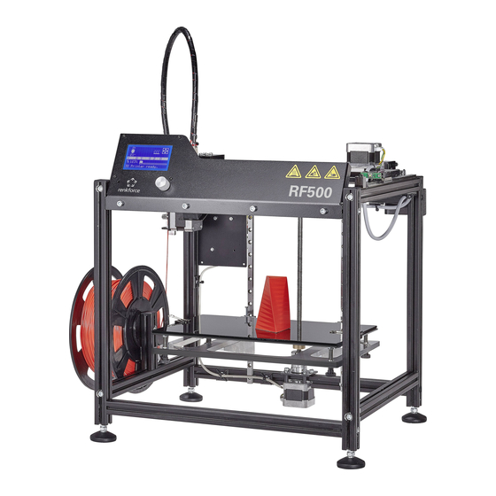
Page 9: Overview Of The Most Important Parts
7. Overview of the Most Important Parts a) Maker Construction Kit / Construction Kit (1) Display (2) Extruder carriage (3) Motor for the X-direction (4) Operating switch (5) Filament feed (6) Printing plate with printing plate support of glass (7) Motor for the Z-direction (8) Filament holder In the small figure on the right, the printing directions (x, y and z) are indicated in the front view. The three yellow arrows in the figure above show the actual directions in the dis- played printer. In addition to the Maker kit, the kit also has a metal housing (like the finished product). -
Page 10: B) Preassembled Device
b) Preassembled Device (1) Display (2) Extruder carriage (3) Motor for the X-direction (4) Operating switch (5) Filament feed (6) Aluminium printing plate and heater (7) Motor for the Z-direction (8) Filament holder In the small figure on the right, the printing directions (x, y and z) are indicated in the front view. The three yellow arrows in the figure above show the actual directions in the dis- played printer. The preassembled device has an aluminium printing plate with heating in contrast to the maker kit. The preassembled device also has a metal housing. The heating and housing can be retrofitted with the construction kit. -
Page 11: Software And Firmware Installation
8. Software and Firmware Installation a) Download and Unpacking of the Software/Firmware Package The software, firmware, tools and printing examples needed for the printer are available online as a download package. This is regularly updated. Therefore, check occasionally whether a new version may be available. • Open the web browser and navigate either to the product page of the printer in our shop www.conrad.com or to our download page (see chapter "3. Intended Use" - Current operating instructions). • Download the package "BUNDEL_Vx_x_x_RENKFORCE_RF500" here (x_x_x designates the package version). • Unpack the downloaded ZIP file on your hard disc. Note that the archive has a very deep path due to the firmware and Arduino software contained. Therefore, we recommend directly unpacking the package into a folder on, e.g., C:\ or D:\. • Find a brief explanation on the folders contained below. "Arduino"... -
Page 12: C) Installation Of The Repeater Host Software
c) Installation of the Repeater Host Software • Install the file "setupRepetierHostRenkforce_x_x_x.exe" from the directory "Repetier-Host" from the download package (x_x_x desig- nates the software version here). Installation of the custom version of the Repetier-Host requires administrator rights, since the necessary configuration files and printer settings will not be installed otherwise. If the corresponding message appears in Windows , confirm it with Yes in any case. - Page 13 • Now select the desired serial connection. For this, click "Select Port". If more than one device is displayed, briefly disconnect the main PCB at the USB connection and then recommend it. The device that disappeared briefly is the right one. • To select the firmware file, click "Load Firmware File". • Usually, the folder in the download bundle that contains the firmware will be opened now. If this is not the case, open the folder "Firmware-Hex"...
-
Page 14: Required Tools And Material
9. Required Tools and Material The second part ("Maker-construction kit / construction kit") of this chapter ("9. Required Tools and Material") and the 3 subsequent chapters ("10. Assembly of the Mechanical Parts", "11. Mounting of the Electrical Components" and "12. Final Work") generally are only relevant for purchasers of the maker construction kit / construction kit. Owners of the preassembled device can skip those chapters. However, the chapters are helpful when there is an error or smaller repairs are necessary. Preassembled device • Hex key 4 mm Maker-construction kit / construction kit • Different screwdrivers (cross-head and slotted) -
Page 15: Assembly Of The Mechanical Parts
10. Assembly of the Mechanical Parts This chapter ("10. Assembly of the Mechanical Parts") generally is only relevant for purchasers of the maker construction kit / con- struction kit. Owners of the preassembled device can skip this chapter. However, the chapter is helpful when there is an error or smaller repairs are necessary. a) General Information Take enough time for the assembly. Hurrying often leads to mistakes that may damage components or ruin the time benefit by elaborate rework. The workplace should be sufficiently large and clean so that the different components and assemblies can be put down and installed easily. Always observe the images during assembly. Here, the assembly locations and correct alignment of the components are shown. All mechanical components of the construction kit are produced extremely precisely. Never apply any force during assem- bly. All parts can be assembled without any great application of force. If this is not the case, rethink the assembly step and reread the corresponding description in these instructions. - Page 16 Use of the slot nuts Push the slot nut into the aluminium profile slot turned by 90° longi- Push, e.g., a small hexagon socket wrench or a similar tool carefully tudinally. into the slot nut's thread. Turn the slot nut up until it "latches" and is held cleanly in the guide. Alternatively, and while the slot of the aluminium profile is still acces- Now you can move it back and forth as desired. sible, you can also push the slot nut into the slot from the side or pull When you tighten the respective screw in the slot nut, always make it out that way.
-
Page 17: B) Assembly Of The Components
b) Assembly of the Components Assembly of the left side part (front view) 1x aluminium profile 284 mm without bore The two short aluminium profiles are the same on both sides. 1x aluminium profile 284 mm with bore at the centre In the long profile with the cut-out for the ball bearing, the cut side of 1x aluminium profile 356 mm with 4 bores and 1 cut-out for the ball bearing the bore, at the height of the cut-out for the ball bearing, must be on 1x aluminium profile 356 mm with 4 bores the left (left red box). 4x cylinder head screw M5x20 In the second long profile, the milled part of the upper bore, to the left of the milled side of the bore, must be below. Assemble the 4 aluminium profiles as illustrated. Screw one cylinder This figure shows the left side part from the outside. - Page 18 Assembly of the right side part (front view) 1x aluminium profile 284 mm without bore The two short profiles are the same on both sides. 1x aluminium profile 284 mm with bore at the centre In the long profile with the cut-out for the ball bearing, the cut side of 1x aluminium profile 356 mm with 4 bores and 1 cut-out for the ball bearing the bore, at the height of the cut-out for the ball bearing, must be on 1x aluminium profile 356 mm with 4 bores the right (left red box). 4x cylinder head screw M5x20 In the second long profile, the milled part of the upper bore, to the right of the milled side of the bore, must be below. Assemble the 4 aluminium profiles as illustrated. Screw one cylinder This figure shows the right side part from the outside.
- Page 19 Inserting the ball bearing into the side parts. 1x side part left First take the left side part (see left figure) and push one of the two ball 1x side part right bearings into the intended cut-out. 2x grooved ball bearing 625Z (diameter inside/outside 5/16 mm) Proceed accordingly for the right side part. Assembly of the deflection shaft 1x shaft 5 mm 1x washer (diameter inside/outside 5.3/10 mm) 1x sprocket 5 mm 1x sprocket, double, 5 mm 1x spacer 6 mm (inner diameter 5 mm) 4x threaded pin M3x5 Assemble the deflection shaft as shown in the figure above.
- Page 20 Assembly of the basic frame 2x aluminium profile 356 mm without bore First take the left side part. Attach the 4 aluminium profiles as illus- 1x aluminium profile 356 mm with square cut-out and 2 bores trated with 4 M5-cylinder-head screws. 1x aluminium profile 356 mm with 2 bores Turn in the screws only loosely. Do not tighten! 1x deflection shaft, assembled The screws always must be screwed in from the milled side of the 2x toothed belt 600 mm respective bore. 1x toothed belt 136 mm The arrow (1) shows the aluminium profile on the front left side. The 8x cylinder head screw M5x16...
- Page 21 Installing the articulated feet 4x foot Screw the counter-nut to the stop in all four ball-head screws. 4x ball-head screw Ø40 M5x20 incl. counter-nut Take the basic frame and put it upside-down. Do not crush the toothed belts. Screw one ball-head screw each into the bottom of the vertical alu- minium profiles (1). Screw the screws in to the stop.
- Page 22 Assembly of the belt tensioners (Y-direction) 3x grooved ball bearing 624Z (diameter inside/outside 4/13 mm) Push the washers onto the screw alternatingly with the ball bearings 1x cylinder head screw M4x25 (screw - washer - ball bearing - washer - ball bearing - washer - 4x washer (diameter inside/outside 4.3/9 mm) ball bearing - washer - washer 20 mm). 1x washer (diameter inside/outside 4.3/20 mm) 2 belt tensioners are needed. The parts list makes up one belt ten- sioner. Installation of the belt tensioners (Y-direction) 2x belt tensioners assembled Push one slot nut each into the inside of the upper aluminium profiles 2x slot nut M4 of the side parts and attach one belt tensioner each to it.
- Page 23 Installation of the guide rails for the Y-direction The guide carriage can generally be pushed off of the respective guide rail, since the bearing balls are combined in a chain. However, we recommend avoiding this if possible. 2x guide rail with guide carriage (235 mm) Push 4 slot nuts into the upper aluminium profiles of the two respec- 8x cylinder head screw M3x8 tive side parts 4 slot nuts. For the other ones, the thread must point 8x slot nut M3 outwards in each case. Remove the two cable ties from the guide rails. Attach one guide rail with guide carriage each loosely to the two pro- Hold a guide rail with guide carriage against the slot nuts and align files with the cylinder-head screws.
- Page 24 Installation of the guide rails for the Z-direction Slide the two knurls on the deflection shaft each to the outside in the 2x guide rail with guide carriage (320 mm) direction of the side part (1). 4x cylinder head screw M3x8 Then attach the toothed belts to the knurls (2). Place the two long 4x slot nut M3 toothed belts provisionally over the two belt tensioners (3). Push 2 slot nuts each into the two aluminium profiles installed cross- Attach the two guide rails with guide carriage to the two profiles, using wise at the rear as illustrated. The slot nuts each must be aligned with the cylinder-head screws as illustrated. the parallel bore. Only tighten the 4 screws slightly!
- Page 25 Installing the Z-motor 1x actuator Push the 2 slot nuts into the lower aluminium profile at the rear as 1x Z-motor holder, black shown in the upper figure. 4x cylinder head screw M3x20 black Take the Z-motor holder and attach it to the two slot nuts with the two 4x spacer 10 mm (diameter inside 3 mm) M5-cylinder-head screws. 4x spacer 2 mm (diameter inside 3 mm) The Z-motor holder must be aligned above the bore of the aluminium 2x slot nut M5 profile. Do not tighten the screws firmly yet! 4x cylinder head screw M5x8 black...
- Page 26 Attachment of the sprocket to the Y-motor 1x actuator Push sprocket onto axe of the actuator and attach it with 2 threaded 1x sprocket 5 mm pins each. A threaded pin must meet the flattened side of the axis. Do 2x threaded pin M3x5 not tighten the threaded pins fully yet. The motor axis must end flush with the upper edge of the sprocket. Optionally, the threaded rods can be secured with threadlocker var- nish.
- Page 27 Installing the Y-motor holder to the basic frame and tensioning the toothed belt 1x Y-motor holder with installed motor Push the 2 slot nuts into the right aluminium profile at the rear as 4x cylinder head screw M5x8 black shown in figure (where the double sprocket is installed). 2x slot nut M5 The threads each must point outwards. Align the two slot nuts with the bores of the Y-motor holder. Attach the sprocket of the motor as shown in the figure to the short Attach the Y-motor holder to the two slot nuts loosely with the two M5 toothed belt of the deflection shaft. cylinder-head screws. To tension the toothed belt, push the Y-motor holder with the motor up until the toothed belt is tensioned so that it can still be twisted by 180° with two fingers.
- Page 28 Aligning the deflection shaft and tightening the double sprocket Now align the deflection shaft. It must be pushed into the ball bearing Now check if the double sprocket is aligned with the spacer on the left. to the same depth as far as possible on both sides. Then tighten the two threaded pins. Check how far the shaft protrudes from the ball bearing on both sides by looking into the slot (where the screwdriver is placed with the shaft on the other side in the figure).
- Page 29 Attachment of the infeed knurl to the filament infeed motor 1x actuator Push the feed knurl onto axe of the actuator and attach it with 2 1x feed knurl 5 mm threaded pins each. A threaded pin must meet the flattened side of 2x threaded pin M3x5 the axis. The feed knurl must be as close as possible to the motor. As refer- ence for the distance, push a feeler gauge sheet with 0.1 or 0.2 mm between the knurl and the motor.
- Page 30 Install the filament feed-through at the extruder motor holder. 1x extruder motor holder Install the inlet for the filament tube to the extruder motor holder as 1x adapter illustrated. First push the adapter into the opening from the outside 1x nut M8 and attach it with the nut. Tighten the nut with an open-faced spanner. 1x quick closure Then screw the quick closure hand-tight as illustrated in the figure. If the adapter does not fit through the opening, simply turn it into the opening.
- Page 31 Assembly of the ball bearing holder 1x extruder motor holder with installed filament infeed motor Assemble the attachment for the ball bearing holder as illustrated. 1x ball bearing holder with assembled ball bearing The order is: 1x counter-holder Cylinder-head screw - counter-holder (small bore) - ball bearing hold- 1x cylinder head screw M3x30 er - spacer 1x spacer 5 mm (inner diameter 3 mm) Install the unit previously assembled in the free bore of the motor. The cylinder-head screw must not be tightened so far that the ball bearing holder cannot be moved freely.
- Page 32 Preparation of the spring holder 1x spring holder Screw the cylinder-head screw completely into the spring holder as 1x cylinder head screw M4x30 (fully threaded) illustrated. Ensure that the screw is turned in from the right side since the bore is slightly offset. Final assembly of the infeed unit 1x extruder motor holder with motor and ball bearing holder Prepare all parts as illustrated.
- Page 33 Thread the M5-cylinder-head screw without washer (or the cylinder- Push the spring holder with the pressure spring (1) including the head screw M5x35 with the plastic washer) through the counter- washer into the corresponding bore of the ball bearing holder (2). Now holder and the right bore of the spring holder into the extruder motor thread the cylinder-head screw (3) through the holder (1). left bore of the extruder motor holder. Fold the spring holder with the pressure spring (2) onto the washer placed before washer (3).
- Page 34 Install the infeed unit on the basic frame 1x infeed unit Push the 2 slot nuts, as illustrated, into the rear aluminium profile of 2x slot nut M5 the left side part. The threads must both point upwards. Align the two slot nuts with the two M5 cylinder-head screws of the infeed unit. Attach the infeed unit in the two slot nuts. Tighten the two cylinder- Now align the infeed unit.
- Page 35 Installation of the guide carriage plate on the left of the basic frame 1x guide carriage plate left Install the left guide carriage plate with the 4 recessed-head screws 4x countersunk head screw M3x10 black on the guide carriage of the left Y-guide rail. Optionally, the screws can be secured with threadlocker varnish. Attachment of the sprocket to the X-motor 1x actuator Push sprocket onto axe of the actuator and attach it with 2 threaded 1x sprocket 5 mm pins each. A threaded pin must meet the flattened side of the axis.
- Page 36 Installation of the X-motor to the right guide carriage plate 1x guide carriage plate right Install the motor with the 4 cylinder-head screws to the right guide 1x actuator with installed sprocket carriage plate (left figure). The motor must be on the same side as the 3x cylinder head screw M3x12 black slot for the guide rail (right figure). The motor plug must be aligned as in the figure (right figure = recessed-head bores on top). Installation of the limit switch to the right guide carriage plate 1x right guide carriage plate with installed actuator Install a limit switch PCB with the two cylinder-head screws M2x16 at 1x limit switch PCB the right guide carriage plate.
- Page 37 Installation of the guide carriage plate on the right of the basic frame 1x right guide carriage plate with motor and limit switch Install the right guide carriage plate with the 4 recessed-head screws 4x countersunk head screw M3x10 black on the guide carriage of the right Y-guide rail. Optionally, the screws can be secured with threadlocker varnish. Check after installing the 2nd guide carriage plate whether both guide carriage plates are straight and parallel with the front alumin- ium profile installed crosswise. If this is not the case, release the attachment screws of the respective aluminium profile to which the guide rail with the guide carriage plate that is not straight is installed.
- Page 38 Tightening the Y-guide rails Move the X-guide rail forward and back in the Y-direction several Move the X-guide rail all the way back in the Y-direction (1), so that times. you can just reach the two rear-most attachment screws of the Y- Observe that the guide carriages do not slide from the Y-guide rail. guide rails anymore (2). Tighten the two screws slightly. Move the X-guide rail forward and back in the Y-direction several times again and tighten the next attachment screws slightly as well.
- Page 39 Installation of the end stop for the Y-direction 1x aluminium block, black Insert the slot nut into the top of the aluminium profile with the right 1x cylinder head screw M3x20 Y-guide rail as illustrated. 1x slot nut M3 Attach the aluminium block in the slot nut with the cylinder-head screw. The aluminium block must be aligned as follows: When the limit switch hits the aluminium block and is actuated (1), the guide carriage still must be completely placed on the guide rail (2). However, it should be only 0.5 to 1 mm from the end of the rail (2).
- Page 40 Attachment of the left Y-toothed belt (viewed from the front) 1x black block with 2 bores Move the X-guide rail forward in the Y-direction until the limit switch 1x black disc with 2 bores hits the end stop. 2x cylinder head screw M4x20 Place the basic frame on its front. First, the left Y-toothed belt (viewed from the front) is attached. Attach the toothed belt to the bottom of the left guide carriage plate Now attach the toothed belt to the belt tensioner.
- Page 41 Attachment of the right Y-toothed belt (viewed from the front) 1x black block with 2 bores Now, the right Y-toothed belt (viewed from the front) is attached. 1x black disc with 2 bores 2x cylinder head screw M4x20 Attach the toothed belt to the bottom of the right guide carriage plate Now attach the toothed belt to the belt tensioner. as illustrated.
- Page 42 Tensioning the toothed belts Put the basic frame on its feet again. If you cannot tension the toothed belt enough by hand, use a screw- First release the screw of the left belt tensioner; tension the belt by driver to move the belt tensioners forwards. pushing the belt tensioner on the inside and tighten the screw again.
- Page 43 Assembly of the belt tensioners (X-direction) 3x grooved ball bearing 624Z (diameter inside/outside 4/13 mm) Push the washers onto the screw alternatingly with the ball bearings 1x cylinder head screw M4x35 (screw - washer - ball bearing - washer - ball bearing - washer - ball bearing - washer - washer 20 mm). 4x washer (diameter inside/outside 4.3/9 mm) 1x washer (diameter inside/outside 4.3/20 mm) Installation of the belt tensioners (X-direction) 1x belt tensioners assembled Guide the assembled belt tensioners into the cut-outs of the left guide 1x washer (diameter inside/outside 4.3/20 mm) carriage plate from below (viewed from the front, the picture has been 1x nut M4 taken from the rear view) and attach it with the washer and the nut.
- Page 44 Assembly of the extruder holders 1x extruder holder Install the belt tappet with the two cylinder-head screws at the rear of 1x belt tappet the extruder holder. 2x cylinder head screw M3x10 black Optionally, the screws can be secured with threadlocker varnish. Assembly of the quick closure 1x extruder holder Screw the quick-closure into the left bore in the top as illustrated (bore 1x quick closure next to the cut-out).
- Page 45 Turning in of the threaded pin 1x extruder holder Screw the threaded pin into the bore by the quick closure from behind. 1x threaded pin M4x8 Only screw in the threaded pin loosely. It must not protrude into the bore for the extruder yet. Assembly of the limit switch and the extruder holder 1x limit switch PCB Mount the limit switch PCB on the extruder holder with the two cylin- 2x spacer 9 mm (diameter inside 3 mm)
- Page 46 Attaching the fan at the fan sheet 1x fan sheet Install the fan on the fan sheet from above with the 3 cylinder-head 1x fan screws and nuts. The screws must be pushed through the sheet and 3x cylinder head screw M2x16 black the fan from behind (from the view as illustrated). The nuts must be 3x nut M2 black on top of the fan.
- Page 47 Assembly of the extruder holder at the X-guide carriage 1x extruder holder assembled Mount the extruder holder on the X-guide carriage with the 4 cylinder- 4x cylinder head screw M3x10 black head screws. The extruder holder must be aligned so that the fan points to the front of the printer. Optionally, the screws can be secured with threadlocker varnish.
- Page 48 Assembly of the X-toothed belt 1x toothed belt 640 mm Attach the toothed belt to the belt tappet as illustrated first. Now attach the toothed belt to the sprocket of the X-motor (1) and If you cannot tension the toothed belt enough by hand, use the open- then across the belt tensioner (2). faced spanner with which you tighten the nut as a lever. Carefully Shift the belt tensioner outwards to tension the belt and tighten the push the open-faced spanner against the silver aluminium block while screw of the tensioner.
- Page 49 Assembly of the undertable 1x undertable Attach the two table tappets with the 4 recessed-head screws to the 2x table tappets undertable from below. The recessed bores in the undertable must 4x countersunk head screw M4x10 black be on top. Optionally, the screws can be secured with threadlocker varnish. Attachment of the limit switch actuation of the Z-axis 1x undertable Turn the nut onto the screw first. Then turn the screw into the left table...
- Page 50 Attachment of the table to the guide rails 1x undertable First put the table into the middle of the basic frame. The sides of the 8x cylinder head screw M3x12 black table should be in parallel to the aluminium profiles. The bore in the table (rear centre) must be aligned with the shaft of the Z-motor. If the 4 screws of the guide rails are not loose, release them a little and move the two guide rails until the guide carriages are at the same level as the table tappet.
- Page 51 Assembly of the spindle 1x spindle Place the coupling on the spindle on the side that has no thread. 1x flange nut Tighten the two left threaded pins (arrows in the figure) of the cou- 1x clutch pling. Simply leave the two right threaded pins loose in the coupling. First, turn the flange nut on the side of the spindle that has no thread. Optionally, the screws can be secured with threadlocker varnish. Align the flange nut as shown in the picture.
- Page 52 Tightening of the table to the guide rails Lift the table and turn the flange nut all the way down. Then put the Measure the distance between the right guide rail and the right alu- table onto the nut. minium profile at the bottom (1) and top (2) each. Align the guide rail at the bottom and top until the distance at 1 and Move the table up and down twice and then to the middle (right fig- 2 is the same. Check that the rails are straight with a stop angle ad- ure).
- Page 53 Final alignment, relieving and tightening of the guide rails The table still must be supported on the flange nut. • Lift the table and turn the flange nut almost all the way up. Put the table back down on it (4). • Loosen all 4 cylinder-head screws of the two guide rails (1), but • Check the upper and lower distances on both sides of the guide only until they can be moved a little. rails again. If necessary, align the rails. • Also release the 4 M5-cylinder-head screws a little that are screwed • Check based on the holes in the guide rails again whether the table into the upper and lower aluminium profiles at the rear from the left is aligned straight, and readjust if necessary. and right (2). • Now tighten the two upper screws of the guide rails slightly so that • Check that the spindle is centred in the bore of the table (3). If this they cannot move anymore (5).
- Page 54 Attach the flange nut to the table. 2x cylinder head screw M4x16 black Lift the table and turn the flange nut almost all the way up. Put the table back down on it. Turn the two cylinder-head screws into the thread bores of the table through the bores of the flange nut from below. Tighten the screws. Optionally, the screws can be secured with threadlocker varnish. Lower the table again by turning the spindle. If you find when turning the table up or down subsequently that it moves stiffly at the top or bottom, release the attachment screws of the two guide rails in sequence. Tighten the screw again before releasing the next one. You may need to release the undertable or the tappets again as well.
- Page 55 Installation of the Z-limit switch 1x limit switch holder plate with limit switch Push the 2 slot nuts into the lower slot of the upper aluminium profile 4x cylinder head screw M5x8 black at the rear as shown in the figure. 2x slot nut M5 The threads must both point outwards. Align the two slot nuts with the hole distance of the end switch holding plate.
- Page 56 Installation of the printing plate 1x printing plate Remove the film from the printing plate first. 4x countersunk head screw M4x40 black Attach the 4 recessed-head screws to the printing plate with the 4 4x pressure spring for printing table (length 24 mm) washer and the 4 nuts. The screws must be pushed in from the side 4x nut M4 black with the countersunk bores.
-
Page 57: Mounting Of The Electrical Components
11. Mounting of the Electrical Components This chapter ("11. Mounting of the electric components") generally is only relevant for purchasers of the maker construction kit / construction kit. Owners of the preassembled device can skip this chapter. However, the chapter is helpful when there is an error or smaller repairs are necessary. The components on the PCBs can be damaged by electrostatic discharge. Therefore, touch, e.g. an earthed radiator before taking any PCBs into your hand. In subchapter c), you will find a wiring plan for the main PCB in which the required line connections are marked. The table also describes the assignment and properties of the individual cables. Before you take the printer into operation, check all cables again for accuracy and proper connection on the main PCB. If you want to mount the metal housing, please observe the additional accessory instructions before installing the main board on the board holder! a) Installation of the Electrical Components Assembly of the extruder 1x heating block Cut about 2 to 3 cm thread sealing tape off of the roll and wind it 1x nozzle 0.4 mm around the thread of the nozzle. - Page 58 1x heating cartridge Insert the heating cartridge into the corresponding opening from 1x cylinder head screw M3x10 above (opposite of the nozzle). 1x heating block Secure the heating cartridge with the cylinder-head screw as illus- trated. 1x nozzle stock Cut about 2 to 3 cm thread sealing tape off of the roll and wind it 1x PEEK part around the short thread of the nozzle stock.
- Page 59 Turn the nozzle stock into the PEEK part carefully. It will only fit in one Push the PTFE insert into the PEEK part. Take a hexagon socket side because the opening is larger on the other side. wrench with at least 3 mm and push the PTFE insert entirely into the Tighten the nozzle stock hand-tight with a 13 mm spanner. PEEK part.
- Page 60 1x extruder lower part Cut about 2 to 3 cm thread sealing tape off of the roll and wind it 1x extruder upper part around the thread of the nozzle stock. 1x PTFE thread sealing tape The sealing tape must never protrude beyond the thread. Turn the extruder top into the extruder bottom to the stop.
- Page 61 1x extruder Push the temperature sensor into the small opening between the noz- 1x temperature sensor zle and the bore with the thread. Attention! The temperature sensor is very sensitive! Installation 1x cylinder head screw M3x8 1x washer (diameter inside/outside 3.2/7 mm) therefore must be performed with the utmost care! Attach the sensor with the cylinder-head screw and the washer. The screw must be turned between the two connection lines for this.
- Page 62 Push the extruder into the left opening of the extruder holder from Push the extruder entirely into the opening and tighten the threaded below (opening where the quick-closure is installed at the top). pin. The extruder must be aligned so that the side of the heating block Use either an angled hexagon socket wrench 2 mm (to tighten from with the heating cartridge points to the left or outside (lower arrow in below) or a straight hexagon socket wrench that you can push through the figure). The heating block must run in parallel with the fan sheet.
- Page 63 Preparation of the display 1x display Push one spacer between the display and control PCB in each at- 4x spacer 3 mm (diameter inside 3 mm) tachment hole. Align the spacer precisely with the holes. Installation of the display in the display holder 1x display holder Remove the film from the display first. 1x display Attach the display to the display holder from the inside. The dial switch 4x cylinder head screw M2.5x20 black must be guided through the corresponding opening.
- Page 64 Align the display when all screws are inserted. Particularly observe that the dial switch does not hit the display holder. Tighten all nuts (hex key 5 mm). You may need to align the display more precisely after commission- ing. Apply the film to the display again to protect it. Installation of the operating button 1x display holder Push the operating button onto the shaft of the dial switch and attach 1x operating button it by tightening the slotted screw.
- Page 65 Installation of the display unit 1x display unit Insert the 4 slot nuts into the upper aluminium profile at the front of 4x cylinder head screw M5x8 black the printer. 4x slot nut M5 Hold the display unit against the slot nuts from above and align them Attach the display unit to the 4 slot nuts with the M5-cylinder-head with the bores in the display unit.
- Page 66 Attachment of the main PCB to the PCB holder 1x PCB holder Attach the main PCB to the PCB holder. 3x hexagon screw M2.5x16 (plastic) The PCB holder and the main PCB must be aligned as illustrated! 3x nut M2.5 (plastic) Begin with the left screw at the middle of the PCB. 1x main PCB Install the screws one at a time.
- Page 67 Pushing on the adapter PCB 1x additional PCB Push the adapter PCB onto the additional PCB as illustrated. All pins 1x adapter PCB in the adapter PCB must be pushed into the socket strip. Pushing the jumpers onto the additional PCB 1x additional PCB 6 pins each are placed between the continuous pin series into which 12x jumper the motor drivers are inserted later (2 rows with 3 pins each). 3 jump- ers each must be put onto these pins. There are 3 fields on the right...
- Page 68 Assembly of the additional PCB 1x PCB holder with main PCB Push the additional PCB onto the main PCB. 1x additional PCB Use the upper double pin strip that runs across the main PCB for orientation.
- Page 69 Assembly of the cooling bodies on the motor drivers 4x motor driver Remove the protective film from the bottom of the cooling element 4x heat sink and stick it centred onto the chip of the motor driver. Attention! Do not stick the cooling body too close to the soldering points of the pin strip! Danger of short-circuit! Repeat this with the other 3 motor drivers.
- Page 70 Assembly of the PCB holder at the printer 1x PCB holder with main PCB Push the 2 slot nuts into the groove of the upper aluminium profile and 4x cylinder head screw M5x8 black the left aluminium profile (viewed from the front) at the rear as shown 2x slot nut M5 in the figure. The threads must be aligned to the right or downwards as illustrated. Hold the PCB holder against the slot nuts and align the two slot nuts with the bores in the PCB holder. Assembly of the cooling bodies on the motor drivers Attach the PCB holder to the two slot nuts placed before loosely with the two M5 cylinder-head screws.
-
Page 71: B) Wiring Of The Electrical Components
b) Wiring of the Electrical Components If you connect a cable to the main PCB, first check the correct connection in the following wiring diagram. Connection plan of the main PCB LCD EXP1 LCD EXP2 Extruder Temp. (04) Trimmer Motorstrom Z Endschalter Z (02) Motor Z (07) (oberer Pin = braun) Endschalter Y (05) Endschalter X (01) Trimmer Motorstrom Y Motor Y (06) (oberer Pin = braun) Trimmer Motorstrom Ext. Trimmer Motorstrom X Motor X (05) oberer Pin = weiß) - Page 72 Wiring of the extruder carriage 1x filament tube approx. 80 cm Optional: Push one clip each onto the quick-closure to additionally 1x cable 01 approx. 990 cm secure the filament tube. 2x clip for quick closure (tube protection) Attention! You can only remove the tube when the clip is destroyed. 1x Elko 220 µF, 25 V This is of interest, e.g., for schools as well, since it prevents easy 1x spiral tube black removal of the clip.
- Page 73 Take all lines of the extruder carriage (cable 01/lines of the heating When you have reached the extruder, push the spiral tube in the di- cartridge, cable 03/lines of the temperature sensor, cable 04) and at- rection of the filament infeed until the spiral tube has reached its end. tach them to the filament tube with 2 to 4 windings of the spiral tube. Then wind in the direction filament infeed. It is recommended to re- Then wind the spiral tube around the cables further in the direction lease the filament tube again from the quick closure of the filament of the extruder.
- Page 74 Take 3 adhesive sockets and glue them to the printer as illustrated. When the length is correct, tighten the cable ties at the cable strand. Degrease the adhesive areas first. Now secure the cable of the fan with the short cable tie (99 mm) to the Take 3 cable ties (142 mm) and fasten the cable strand loosely to the cable of the X limit switch at the extruder holder. adhesive sockets with them. If the cable is too tense then, you may need to cut off a piece of the filament tube so that the cables can be placed cleanly (see next fig- ure).
- Page 75 Connection of the Z limit switch 1x cable 02 approx. 220 mm Connect cable 02 to the connection plug of the Z-limit switch PCB and place it through the cut-out of the main PCB. Connect the other end to the two pins that are marked "limit switch Z"...
- Page 76 Connection of the motor for filament infeed 1x cable 08 approx. 280 mm Connect cable 08 to the connection plug of the motor for the extruder and place it through the cut-out of the main PCB. Connect the other end to the connection "Motor ext. 0" (see connec- tion plan).
- Page 77 Connection of the display 2x flat cables (both identical) Connect the first cable to the connection "EXP2" at the display and the main PCB each. From the view illustrated, the cable must go into the respective right connection plug. Then connect the other cable to the respective connection "EXP1" (the respective left plug). Take the 4 adhesive sockets and 4 cable ties (142 mm) and fasten the Degrease the adhesive areas first. two cables as illustrated in these two figures.
- Page 78 Finally, fasten the cable ties in sequence.
- Page 79 Connection of the motor for the X-direction and the Y-limit switch 1x cable 05 approx. 890 mm Thread the cable through between the aluminium profile and the toothed belt from below and then past the limit switch PCB at the rear. Connect the 6-pin plug to the X-motor and the 2pin one to the Y-limit switch. Take 1 adhesive socket, 1 cable tie (142 mm) and 1 cable tie (99 mm). Place the cable behind the guide rails and thread it through the cut- Fasten the cable with the adhesive socket and the long cable tie as out at the top near the main PCB from the inside.
- Page 80 Take the 4 adhesive sockets and 4 cable ties (142 mm) and fasten Pull the cable tie almost all the way together at the arrow so that the the cable as illustrated in it and the right figure. Do not tighten the cable can barely be moved anymore. cable ties yet. Additionally hold the cable in this place and move the carriage back- Degrease the adhesive areas first. wards in the Y-direction. If a good loop forms as in the figure, hold the cable in that position.
- Page 81 Connection of the motor for the Y-direction 1x cable 06 approx. 450 mm Connect the 6pin plug to the Y-motor. Do not swap the cable with cable 07, since it is only 50 mm longer and Thread the cable through the two open cable ties and then past be- almost identically assigned. hind the limit switch PCB.
- Page 82 Connection of the motor for the Z-direction 1x cable 07 approx. 500 mm Connect the 6pin plug to the Z-motor. Do not swap the cable with cable 06, since it is only 50 mm shorter Connect the 4pin plug to the connection marked in the connection and almost identically assigned.
- Page 83 Attachment of the cables to the main PCB Place and fasten the cables at the main PCB. Take long cable ties (142 mm) for the thicker cable strands and the short cable ties (99 mm) for the thinner cable strands. Assembly of the connection plug for the mains unit 1x mains unit Connect the two lines of cable 09 to the connection plug of the main 1x cable 09 approx. 85 mm (2 lines; 1x red; 1x black) PCB. 1x connection plug from the main PCB (green) The black line goes into the terminal at the far right, the red one into the terminal to the left of it.
- Page 84 The white line of the mains unit is plus, the black one minus. Reconnect the plug with the mains unit to the main PCB. Now connect the white line of the mains unit and the red line to the left terminal of the plug. Of course, you can remove the plug again for further work until com- The black line from the mains unit and the other black line go into the missioning.
-
Page 85: Final Work
12. Final Work This chapter ("12. Final Work") generally is only relevant for purchasers of the maker construction kit. Owners of the preassembled device can skip this chapter. Gluing on the rating plate and warning signs Attach the rating plate to the front cover from behind, as illustrated. Attach the silver warning text sign well visibly to the middle of the front Degrease the adhesive area first. cover as illustrated. Degrease the adhesive area first. - Page 86 Attaching the end caps Push one end cap each onto all four vertical aluminium profiles. If you Push the fifth end cap onto the aluminium profile of the filament holder. cannot push them in manually, use a hammer and a suitable exten- sion with a flat, supported surface. If you purchased the kit, including the metal housing, install now the remaining parts of the housing. Please refer to the additional accessory instructions.
-
Page 87: First Commissioning
13. Initial Commissioning a) Assembly of the filament holder 1x filament holder Attach the filament holder to the short aluminium profile from the in- 1x cylinder head screw M5x20 side with the cylinder-head screw M5x20. 1x washer M5 (Ø outside 15 mm) Attach the washer to the outside of the filament holder with the other 1x cylinder head screw M5x16 cylinder-head screw. Please note! The figure shows the construction kit. The short profile is covered by the housing in the preassembled device. Install the filament holder in the corresponding opening from the outside here. -
Page 88: C) Setup And Transport
c) Setup and Transport When setting up the 3D printer, observe that the mains unit and the mains cable must be easy to reach so that the device can be switched off quickly and easily or be disconnected from the voltage supply in case of malfunction. Ensure proper ventilation when setting up the device. Do not put the device down on soft support such as a carpet or bed, etc. the air circulation also must not be impaired by other objects. This prevents heat dissipation from the product and may lead to overheating (danger of fire). When setting up the device, make sure that it has a stable footing and place it on a stable underground. Persons may be injured if the 3D printer drops. When setting up the device, make sure that the connection cables are neither pinched nor damaged by sharp edges. Always place the cables so that no one can trip over them or be caught in them. There is a danger of injury. Never place the device on any valuable or sensitive furniture surfaces without sufficient protection. • Put up the 3D printer on a level, stable and non-vibration-sensitive surface. • If you want to transport the 3D-printer, disconnect the mains unit from the main PCB, by disconnecting the green plug (first disconnect the mains unit from the mains). Also remove the printing plate support (only in the construction kit). Only use suitable packaging for dispatch! Particularly observe that all moving parts are secured, e.g. with cable ties! Pack the printing plate support separately in bubble wrap (construction kit only). -
Page 89: E) Adjustment Of The Motor Driver
e) Adjustment of the Motor Driver Before first use of the printer, the 4 motor drivers must be reconciled. This is done generally at first by comparing the potentiometer on your controller to the respective screen. Finally, the fine settings are made with a digital multimeter. This should be able to meas- ure 300 mV and 500 mV as precisely as possible. This subchapter is only relevant for purchasers of the maker construction kit, since the motor drivers in the preassembled device have already been reconciled in production. Owners of the preassembled device can therefore skip this chapter. It is, however also possible that the motor drivers need to be adjusted later. -
Page 90: Operation At The Printer
14. Operation at the Printer a) Display and Operating Buttons (1) Temperature extruder (target) The target temperature it not displayed here yet, since the ex- truder is not heated yet. (2) Temperature extruder (actual) (3) Printing speed (4) Status information (5) Status of the heating bed (optional) (6) Status of the extruder fan; when it runs, the current speed in % is displayed below. (7) Status and position of the 3 axes X, Y and Z; indication in mm (8) Status of the SD card (9) Setting controller for the display contrast... -
Page 91: B) Menu Overview
b) Menu Overview Operation takes place via the operating switch at the printer: • Turning the actuating button serves navigation in the menu structure (up/down) or adjustment of values. • Pushing the operating button serves confirmation of a selection in the menu and calling of the menu structure from the main menu. The menu structure may deviate slightly depending on firmware. Info screen Prepare Main Auto home Set home offsets Move axis Prepare Move 10 mm Move axis Move X Move X: +000.0 Move Y Move Y: +000.0 Move 1mm Move axis Move X... - Page 92 Control Temperature Ext. Min: 210 Ext. Min: Ext. Max: 250 Ext. Max: Ext. Fact: 000.10 Ext. Fact: 000.10 PID-P: +022.20 PID-P: +022.20 PID-I: +001.08 PID-I: +001.08 PID-D: +114.00 PID-D: +114.00 PID-C: 100 PID-C: Preheat PLA conf Temperature Fan speed: 0 Fan speed: Nozzle: 180 Nozzle: Bed:...
-
Page 93: C) Functions Of The Individual Menu Items
c) Functions of the Individual Menu Items The top-most point in each submenu (to be recognised by the unwound arrow upwards) switches back to the respective previous menu. Therefore, these items are not included in the explanation. Info screen Switches back to the main display Prepare Auto home Move all axes into the home position Set home offsets Specify the zero point - perform a homing run with the repeater software and then execute "Set home offset"; first set the distance (works only after restart of the software) (you can also set an offset, e.g. to print onto an object) Move axis Move 10 mm Move X Moves the X-axis in steps of 10 mm Move Y... - Page 94 PID-D: +114.00 Controller values for hot end PID-C: 100 Controller values for hot end Preheat PLA conf Fan speed: 0 Setting the fan speed for the function "Preheat PLA" Nozzle: 180 Setting the extruder temperature for the function "Preheat PLA" Bed: 70 Setting the printig plate temperature for the function “Preheat PLA”...
-
Page 95: Calibration
15. Calibration a) General Notes on Calibration Attention! Never touch the hot extruder or the hot heat bed (preassembled device only)! There is a danger of burns! When heating, there may be slight development of smoke or steam. This is normal. Please ensure the corresponding ven- tilation. While calibration is underway, no filament must be inserted in the extruder. If there already is some filament in the extruder, it must be completely removed before calibration. For this, observe chapter "16. c) Removing and Changing the Filament" or method 3 in chapter "21. b) Cleaning". Also ensure that the extruder nozzle is clean on the outside. If it is contaminated, clean it as described in chapter "21. b) Cleaning". The extruder or the nozzle must be cleaned so that no filament escapes anymore when they are heated to printing tempera- ture. The following description shows calibration universally for the maker construction kit and the preassembled device. Subchapters "15. -
Page 96: B) Setting Of The Z-Stop
b) Setting the Z-Stop Before starting calibration, set the end stop in the Z-direction. The hexagon screw should be about 1 to 2 mm in the thread. Counter the screw with the counter-nut. Check that the Z-limit switch is clearly pushed by the hexagon screw. Move all axes into the home position Push button for the operating knob (10) in the main menu. -
Page 97: C) Heating To Printing Temperature
c) Heating to Printing Temperature Push button for the operating knob (10) in the main menu. Turn the operating knob (10) until you have selected the menu item "Control" and push the button of the operating knob (10). Turn the operating knob (10) until you have selected the menu item Turn the operating knob (10) until the menu item "Nozzle: 0" is se- "Temperature" and push the button of the operating knob (10). lected and push the button of the operating knob (10). Turn the operating knob (10) to the right until the desired value "220" Now the same value as set before should be shown here. (here: 220 °C) is displayed. The extruder is heated up at once after In our example, we have preselected the maximum temperature of turning. the filament used. You can adjust the value according to your fila- To return to the menu, push the operating knob (10). - Page 98 Turn the operating knob (10) until the menu item "Bed: 0" is selected Turn the operating knob (10) to the right until the desired value "60" and push the button of the operating knob (10). (here: 60 °C) is displayed. The heating element is heated up at once after turning. To return to the menu, push the operating knob (10). Now the same value as set before should be shown here. The printer will switch back to the main menu automatically after a In our example, we have chosen the optimal temperature for the fila- few seconds. The previously set target temperature and the current ment used (here: PLA). You can adjust the value according to your temperature of the extruder below are displayed here.
-
Page 99: D) Setting The Printing Plate
d) Setting the Printing Plate The 4 knurled nuts at the bottom of the table can be used to adjust Generally set the distance between the nozzle and the printing plate the printing plate. support. The distance should be equal everywhere if possible. First, turn all 4 knurled nuts to the right (this will move the printing Then start the fine settings. -
Page 100: Inserting, Removing And Changing The Filament
16. Inserting, Removing and Changing the Filament a) Inserting the Filament - Mechanical Part Push the filament roll on the shaft of the filament holder. The filament Push the ball bearing holder and insert the filament into the groove roll must move freely. of the ball bearing from below through the opening of the extruder The tip of the filament should be cut slightly diagonally. This makes motor holder. insertion easier. Push the filament past the infeed motor and through the entire fila- It must be possible for the feed motor to turn without slippage or ment tube. When it is visible at the other end of the tube (at the ex- catching when pulling or pushing at the filament. -
Page 101: B) Inserting The Filament Via The Printer Menu
b) Inserting the Filament via the Printer Menu Before inserting, removing or changing the filament, the corresponding extruder must be heated up so that the filament can be inserted into or removed from the extruder cleanly. Do not touch the hot extruder nozzle when inserting, removing or changing the filament! Danger of burns! Always wait for the extruder temperature to be reached at filament change and let the extruder heat for approx. another minute, since the extruder may be damaged otherwise. When heating, there may be slight development of smoke or steam. This is normal. Please ensure the corresponding ven- tilation. Move all axes into the home position First, move all axes into the home positions via the function "Auto home". Use the description from chapter 15 as reference. Calibration". Move all axes into a certain position Push button for the operating knob (10) in the main menu. - Page 102 Go to the item "Move X" and push the button of the operating knob Turn the operating knob (10) to the right until the desired value (10). "+110.0" is displayed. The extruder carriage is moved to the set X- position. To return to the menu, push the operating knob (10). Go to the item "Move Y" and push the button of the operating knob Turn the operating knob (10) to the right until the desired value (10).
- Page 103 The printer will switch back to the main menu automatically after a few seconds. The axes are displayed with the current position values here now. Heat up the extruder Push button for the operating knob (10) in the main menu. Turn the operating knob (10) until you have selected the menu item "Control" and push the button of the operating knob (10). Turn the operating knob (10) until you have selected the menu item Turn the operating knob (10) until the menu item "Nozzle: 0" is se- "Temperature" and push the button of the operating knob (10). lected and push the button of the operating knob (10).
- Page 104 Turn the operating knob (10) to the right until the desired value "220" Now the same value as set before should be shown here. (here: 220 °C) is displayed. The extruder is heated up at once after In our example, we have preselected the maximum temperature of turning. the filament used. You can adjust the value according to your fila- To return to the menu, push the operating knob (10). ment. The printer will switch back to the main menu automatically after a few seconds.
- Page 105 Turn the operating knob (10) until you have selected the menu item Turn the operating knob (10) until you have selected the menu item "Move axis" and push the button of the operating knob (10). "Move 1 mm" and push the button of the operating knob (10). Go to the item "Extruder" and push the button of the operating knob Turn the operating knob (10) to the right until the desired value, e.g., (10). "+090.0" is displayed. The extruder infeed moves the filament by the set value. You need to choose the value so that a little filament is extruded. It is possible that you have to wait for a specific value (e.g. +030.0) to be reached before you can increase the value again. To return to the menu, push the operating knob (10). Switching off the extruder heating Now go to the menu "Control" and the item "Nozzle: 220", and push Turn the operating knob (10) to the left until the value is set to 0. The the button of the operating knob (10).
-
Page 106: C) Removing And Changing The Filament
Now the same value 0 as set before should be displayed here. The printer will switch back to the main menu automatically after a few seconds. Now the target temperature is displayed at 0 °C here as well. Below this, the dropping current temperature of the extruder is displayed. Insertion of the filament is then completed. As an alternative to the described method, you can insert the filament manually into the extruder as well after heating. c) Removing and Changing the Filament Hold the filament when it moves out of the ball bearing holder. Otherwise, it may jump out and cause injury. The upper lay- ers of the respective filament roll may jump open as well, which may cause the filament to tangle. -
Page 107: First Print Of An Example Object From The Sd Card
17. First Print of an Example Object from the SD Card When heating, there may be slight development of smoke or steam. This is normal. Please ensure the corresponding ven- tilation. If you are using PLA filament for printing and using the maker construction kit, stick the enclosed adhesive film on the printing plate for better adhesion of the printed object. Use the enclosed glue stick for the preassembled device. Alternatively, you can use a slightly structure masking tape or special glue adhesive masking tape (Conrad order no. 1093104) that has been developed specifically for this purpose. The printing files can be found in the download package in the folder GCODE-PLA. Before starting, download the current download bundle. The corresponding download can be found on the product page of our website or in the download area. In our example, the object "20_20_20Q.gcode" from the download bundle is printed. Please note! The preassembled file from the download bundle is sliced without heating. If you are using the preassembled device or the construction kit with heating, slice the file anew (instructions starting in chapter "19. e) Placement of a Printing Object in the Software"). You may need to activate heating in the slicer settings first (chapter "19. h) More Detailed Description of the Slicer Func- tions"). Alternatively, you can use the adhesive film or adhesive tape to increase adhesion. - Page 108 The display switches back automatically to the main menu. The extruder is heated up. Then move the axes to their home positions. Once the extruder has reached its operating temperature, printing When the fan starts to run, the current speed is displayed under the starts. The display shows the positions of the individual axes (7). The fan symbol in % (6).
- Page 109 It is possible that filament chips collect over time at the filament feed knurl. They should be removed under all circum- stances (if possible) at once, e.g. by blowing off. Check and clean the filament feed knurl regularly! Otherwise, it is possible that the chips will adhere to the knurl and that no filament can be conveyed anymore because of this (the knurl slips through then). The fan at the extruder runs by default from 4th layer for PLA and ABS, provided that the slicer settings have not been changed. If the fan does not run properly, check if it may be attached unevenly.
-
Page 110: General Notes On 3D Printing
18. General Notes on 3D Printing The print quality of 3D printers depends on a great many factors. It is not always possible to achieve a satisfactory print result at the first attempt. Extruder temperature The best extruder temperature depends on the filament material and the printer layer thickness. The manufacturer information for the printing temperature can vary very strongly here. Perform the first test prints at a temperature in the middle range of the manufacturer's information. To optimise the print quality, print the same object with the same printing layer thickness and different extruder temperatures in 5 °C steps and then compare the results. This way you can approach the best extruder temperature for different filaments and printing layer thicknesses most easily. If the extruder temperature is set too hot, the material cannot cool off fast enough and will melt the layer below again. If the extruder temperature is too low, the filament will not become liquid enough and the filament flow is not homogeneous. The individual fila- ment layers also cannot combine sufficiently. -
Page 111: Software "Repetier-Host
19. Software "Repetier-Host" a) General Notes on Software It is unfortunately not possible to explain the complete function of the enclosed software in the scope of this instruction. For this, we refer to the integrated online help function and the information on www.repetier.com. The basic operation and the path to the first printout are, however, described below to that you can get a result quickly and easily. -
Page 112: C) Connection Of The Connected Printer
c) Connection of the Connected Printer Start the programme Repetier-Host and click on "Printer Settings" at the upper right in the window. (1) Select the printer "RF500_3D" in the menu above. (2) Set the port and check the baud rate. If you have selected the right printer in (1), the baudrate (2) is already correctly pre-set to "115200". The port number (2) is system-dependent. Usually, the setting "Auto" should work with the current version of the software (as of 1.6.2). If this does not work properly for you, you can check the port in the device manager of the control panel, under connections (COM and LPT). - Page 113 Click "Connect" in the upper left of the main screen of the software. After a few seconds, the symbol appears in green and the label turns to "Disconnect". The printer has successfully been connected to the software and only some manual settings can be tested.
-
Page 114: D) Manual Operation Via The Software
d) Manual Operation via the Software Click the tab "Manual Control" (1) on the main screen of the software. Before trying out manual printer control, the settings for the limit switches for the Z and Y axes must have been performed. In the preassembled device, the basic settings have already been performed at production but should be inspected again for reasons of safety. If this is not observed, there may be damage to the 3D printer (loss of warranty/guarantee). (2) All axes move into the home position (3) X-axis moves into the home position (4) Y-axis moves into the home position (5) Z-axis moves into the home position (6) The arrow icons can be used to operate the corresponding axes manually. Depending on where the arrow is clicked, differently long routes are run. The route length is displayed when the mouse pointer is moved across the corresponding button of the arrow. (7) Selecting the extruder (optional) (8) Filament feed for the chosen extruder (extruder must be heated up!) (9) Setting of the printing speed... -
Page 115: E) Placement Of A Printing Object In The Software
e) Placement of a Printing Object in the Software Click the "+" symbol on the main screen of the software in the object placement tab. Select the desired file and click "OK". Alternatively, you can also simply pull the file into the software. The 3D object "drops" onto the printing plate in the main window. The following file types can be opened with this software: *.stl (STL-files) *.obj (OBJ-files) *.3ds (3D-Studio-files) In the folder "STL" in the download package, you will find a few examples for the first printing attempts. However, there are many places online where you can download 3D files (e.g. www.thingiverse.com). Alternatively, you can, of course, also use a 3D programme to make your own. - Page 116 Short description of the most important buttons in the "Object Placement" tab: (1) Saving the object (2) Adding objects (as described above); several objects can be addend (3) Copying objects for multiple printing (in another window, the number of copies can be chosen) (4) Centring the object on the printing plate (5) Mirroring the object (6) Deleting the object from the printing plate (7) Scaling the object Use the scaling function to compensate the size retention of the printed object here as well. If it is known, e.g., that the filament material used shrinks by 2 %, set the scaling to the value 1.02 (this is an approximate reference value). After printout, you can meas- ure the object and adjust scaling again if required. (8) Turning the object (9) Showing the cross-section of the object 1 2 3...
-
Page 117: F) Preparation For Print
f) Preparation for Print To be able to print the object, it first needs to be sliced into individual printing layers. This process is referred to as "slicing". Slicing of the placed printing object (1) Select suitable slicer settings for your print. The settings are always marked with the following routine: Printer_Filament material_Layer thickness_Nozzle diameter Example: RF500_PLA175_200_04 = RF500_1.75 mm PLA_layer thickness 200 µm (= 0.2 mm)_nozzle diameter 0.4 mm Always use the same settings in the input fields "Print Setting", "Printer Settings" and "Extruder 1". The heating in the profiles for PLA is switched off by default. If you want to use these, you need to activate the function in the cor- responding slicer profile (see chapter "19. h) More Detailed Description of the Slicer Functions"). (2) Further settings can be made optionally here. However, this should only be done by experienced users. For functions, see the online help function of the software. (3) Click "Slice with Slic3r", to slice the 3D file. The best printing results can be achieved with the profile with the smallest layer thickness. This would be the profile "RF500_PLA175_100_ 04". Printing will take longer accordingly. - Page 118 The preassembled printing file appears in the graphics window after calculation. To the right of this, you will see a small overview for printing. This layer view serves to check for errors before printing. At the very left of the screen, there is a tool bar that serves view control. For more detailed descriptions of the functions, see the online help function of the software.
-
Page 119: G) Print
g) Printing The printing file produced in this manner can be printed now. There are two options for this: • Save the printing file on an SD card to print out stand-alone. For this, click "Save to file" (1). This saves the file as *.gcode and must be set at the same time when you save the file from the G-code editor (disc icon). The precise content of the G-code will be saved into the file here. • The second possibility is to send the file directly to the connected 3D printer via the USB interface of the computer and print it. • Click "Print Preview" and then the button "Print" (3), to start the printout. • While printing, the log window (4) below the image shows current information on software, slicer and printer. • You can also track progress of your print in the main window (5). - Page 120 The graphics window may be switched to display temperature curves. There, the temperatures and their course are graphically displayed in a chart. During the first centimetres of printing, the distance between the printing plate support and extruder can be carefully fine-adjusted manually with the 4 knurled screws at the bottom of the pressure plate. Turn all 4 knurls alternatingly and observe the printed line. For this setting, observe that the extruder must not touch the printing plate support since it may be damaged otherwise (loss of warranty/guarantee).
-
Page 121: H) More Detailed Description Of The Slicer Functions
h) More Detailed Description of the Slicer Functions Below some settings of the slicer are explained that are only to be changed by experienced users. The use of wrong set- tings can result in damage to the 3D printer or defective printouts. Beginners should first work with the basic settings that are integrated in the custom version in any case. If you make any changes to the settings, these must be saved in the configuration settings by clicking the disc icon. Save the different settings as a configuration setting. Assign unique names for the different configuration settings so that you can assign them uniquely to the different filament types, print resolutions, etc. later. For more information, read the integrated online help function. Click the software in the tab "Slicer" (1) to "Configuration" (2) in the right window. The Slicer window is opened (this may take a few seconds). - Page 122 Print Settings (1) Layer height (resolution of the printed object) (2) Layer height of the first layer (influences the adjustment and adhesion on the printing plate; set the first layer a little thicker than the follow- ing layers) (3) Number of the outer wall layers (4) Activate for hollow bodies (e.g. vases) (5) Filled layer number top/bottom (1) Object filling (0-100%) We recommend object filling of 10% to 40%. (2) Filling pattern of the object and the first and last layer...
- Page 123 (1) Loops are circles, that are drawn around the object when printing starts, stabilise the filament flow before the actual object is printed. Here, number, distance from the object, height and minimum length are specified. (2) "Brim" is a thin edge that is placed right around the object to increase the footprint and thus adhesion to the printing plate. Here, the width of the brim is specified. (1) Selection and adjustment of the supporting material that is needed when printing complex objects such as bridges or hollow spaces (poss. required for printing object with overhangs > 45°). The first printing attempts should be without a supporting brim since the result here is usually better again.
- Page 124 You can set or adjust all speeds here. Chance the values only in small steps. Set the number of extruders here.
- Page 125 The extrusion width for all the different print versions can be set here. The extrusion width is the width of the output plastic thread. E.g., this may be increased at the first layer, so that the bottom of the printed object becomes denser.
- Page 126 Filament Settings (1) Filament diameter and filament diameter tolerances according to the manufacturer's specifications are set here. If no manufacturer's speci- fication is present, these values can also be measured with a calliper (measure 1 m of filament material in 10 different points and then set the average here). (2) Temperature setting for the extruder and heating bed (in the preassembled device or when using the optionally available heating plate kit) separated by first and all other layers. In some settings (e.g. PLA), the heating is deactivated by default. If this is to be used, the function needs to be activated first by set- ting a temperature. Observe the settings recommended by the filament manufacturer! Since the best values may fluctuate extremely depending on the filament manufacturer, perform your own tests based on the pre- settings to achieve the best printing quality. When performing the tests, proceed in 5 °C steps and compare the results during or after printing with other settings. The first layer should always be printed a little more hotly for better adhesion on the printing plate. (1) Here you can choose between automatic cooling and permanent operation of the fan at the extruder. (2) Setting of the fan speed.
- Page 127 Printer Settings (1) Geometric data of the printing plate (2) Number of the extruders (1) The starting code contains the first commands that the 3D printer performs. (2) The end code will be performed at the end of the print and could contain, e.g. the run into a removal position for the printed object. Detailed information on the G-Codes can be found, e.g., in http://reprap.org/wiki/G-code.
- Page 128 (1) Setting of the nozzle diameter (2) Settings for the filament withdrawal if the extruder moves to another position of the printed object during printing. If the filament was not withdrawn here, there would be drop or string formation that would negatively influence printing quality.
-
Page 129: I) Setting Up Another Slic3R Version
i) Setting up Another Slic3r Version This chapter describes how to set up another version of the slicer "Slic3r", e.g. if you want to use an older version as well or if a new version has been published since. • First download your desired version of Slic3r. You can find the corresponding download under the following address. http://slic3r.org/download Then click the button "Windows". If you want to download an older version, click the folder "old/"... - Page 130 • In the menu "Slicer", choose the desired Slicer that you want to integrate. In our example, this would be the standard selection "Slic3r". • In the field "Name", enter the desired name and confirm by clicking "Add Slicer". • Select the newly added Slic3r by clicking it (1). • Right-click "Browse" (2). • Navigate to the new Slic3r program directory in the window that opens and select the starting file, in our example "slic3r.exe", by double- clicking (3). • Select the "Slic3r" version (4) and confirm with "Apply" (5). Close the window with the X in the upper right corner (6).
- Page 131 • In the tab "Slicer", select the newly added slicer in the drop down menu to slice an object. The settings "Print Setting", "Printer Settings" and "Extruder 1" are the same for both versions of the Slic3r. Of course, the configuration menu "Manager" also permits integrating another Slicer. The configuration here is similar, but is indi- vidually customised to each slicer, of course.
-
Page 132: Firmware Update
20. Firmware Update The firmware of the main PCB is updated frequently to optimise the properties of the 3D printer. The currently installed firmware version of your printer is briefly displayed in the upper display line after switching on the printer. New versions of the firmware are contained in the download package "BUNDEL_Vx_x_x_RENKFORCE_RF500". Update process The printer must be connected to the USB interface of the computer and must not be connected to any other software (for Repetier-Host, e.g. click "Separate"). Use only Arduino version 1.6.5. The links for download can be found below or in the download package. The first link leads to the main page. You can find the download there in "PREVIOUS RELEASES". The second link downloads the right version as a ZIP file and the third link as EXE file for installation. https://www.arduino.cc/en/Main/Software https://www.arduino.cc/download_handler.php?f=/arduino-1.6.5-r5-windows.zip https://www.arduino.cc/download_handler.php?f=/arduino-1.6.5-r5-windows.exe • Unpack the downloaded Arduino software. • Execute the file "arduino.exe" (folder "Arduino" and its version subfolders until you find the file "arduino.exe"). • In the menu "Tools" (1), select option "Board" (2) and set the type "Arduino/Genuino Mega or Mega 2560" (3). - Page 133 • In the menu "Tools" (1), select option "Processor" (2) and set the type "ATmega2560 (Mega 2560)" (3). • In the menu "Tools" (1), select the option "Port" (2) and set the correct port (3). The port number is system-dependent. You can find it in the device manager of the control panel, under connections (COM and LPT).
- Page 134 • In the menu "File", choose the option "Open..." and select the file "Marlin.ino" from the download package. The file "Marlin.ino" can be found under the following directory path, depending on whether your printer has a heating bed installed or not: \Download Bundel Vx-x-x.zip\Firmware-Source\Firmware RF500\Marlin-with-bed\Marlin-x.x.x\Marlin\Marlin.ino \Download Bundel Vx-x-x.zip\Firmware-Source\Firmware RF500\Marlin-without-bed\Marlin-x.x.x\Marlin\Marlin.ino • A new window opens. • In the new window, click the button with the arrow to the right in order to transfer the new firmware to the 3D-printer. Once the update has started, the USB connection to the printer must not be interrupted. This may cause irreparable damage. • After a successful firmware update, the 3D-printer will start again and briefly display the new firmware version in the first display line after the start.
-
Page 135: Maintenance
21. Maintenance a) General Information Periodically verify the technical safety of the 3D printer, e.g. check for damage to the mains unit or of its mains line. If you have reason to believe that the device can no longer be operated safely, disconnect it immediately and make sure it is not operated unintentionally. -
Page 136: C) Nozzle Change
Cleaning the printing plate Be careful in the preassembled device or when using the optional heating plate kit: Danger of burns. Let the heating plate cool off before cleaning. Clean and degrease the heating plate thoroughly with a soft rag after each print. If you are printing directly on the glass panel, use a little ac- etone for cleaning. If you are using the adhesive film use a mild detergent with alcohol. e) Nozzle Change Caution: Danger of burns. Do not directly touch the hot nozzle and the extruder. • To replace the extruder nozzle, the extruder must first be heated to a temperature suitable for the inserted filament material. • When the temperature is reached, remove the inserted filament material as described in chapter "16. c) Removing and Changing the Fila- ment". - Page 137 • Turn the extruder nozzle back into the heating block and tighten it carefully with a ring spanner, open-faced spanner or hexagon wrench (2). Never apply any strong forces for this. Secure the heating block again by twisting with an 11 mm open-faced spanner. • Then insert the filament again as described in "Inserting the Filament". • Switch off the extruder heating again and have the extruder cool off. View of the nozzles The following figures are to enable you to check your installed nozzle in case of a bad print pattern or if not enough filament is extruded. For example, it is possible that the tip of the nozzle is set incorrectly or comes into contact with the printing plate due to a printing error, and is scraped or damaged by this.
-
Page 138: Troubleshooting
22. Troubleshooting With this 3D printer, you have purchased a product that is built to the state of the art and operationally safe. Nevertheless, problems or errors may occur. Therefore, we would like to describe how to eliminate possible errors here: Always observe the safety information! The 3D printer does not work after connecting the voltage supply. The display and the LEDs on the main PCB remain dark: • Check the connection of the mains line at the mains unit, the mains unit and the connection of the mains unit to the printer. - Page 139 Printing stops during the process: • Check the settings of your computer. It must not switch to standby mode while printing (energy option settings) or simply shut down (instal- lation of software or software updates during printing). • The printing table and its guide must not be installed tensed. In this case, loosen all screws, align the parts and tighten the screws again. The printed object does not adhere to the printing plate: • Use the enclosed adhesive film (only in the maker construction kit) or the enclosed glue stick (only for the preassembled device). This in- creases adhesion of the printed object on the printing plate. You can also use cleaning tape or a slightly structured masking tape as well as Kapton masking tape or blue adhesive masking tape (Conrad order no. 1093104). • There are residues on the printing plate that prevent adhesion of the object. Rub the printing plate with a soft cloth that is soaked with a solvent (e.g. acetone). If you are using the adhesive film, use no aggressive cleaning agents for this. The printed object does not adhere to the printing plate (only in the preassembled device or when using the optionally available heating plate kit): • If you are using the heating plate, the temperature of the heating plate may be set incorrectly. Experiment with the temperature settings in steps of 5 °C for a prefect print result. • When printing problematic objects, it is beneficial to let the optional heating plate heat up for approx. 15 minutes before printing. • Check whether the heating (red foam material) adheres cleanly to the ceramics printing plate. It must not come loose (even partially). If this is the case, the temperature distribution of the heating plate is insufficient and the printed objects cannot adhere well. • The heating plate has not reached the set temperature yet. The printed object cannot be removed from the heating plate (only in the preassembled device or when using the optionally available heating plate kit): • If you are using the heating plate, wait until it has cooled off to below 40 °C. • Use a glass scraper or a knife to remove the object. Repairs other than those described above should only be carried out by an authorised specialist.
-
Page 140: Handling
23. Handling • Never connect the mains plug to a mains socket immediately after the device has been taken from a cold to a warm environment. The result- ing condensation may destroy the device. Allow the device to reach room temperature before connecting it. Wait until the condensation has evaporated. • Never pull the mains plug from the mains socket by the cable. Only pull it from the mains socket by the intended grip areas. • Disconnect the 3D printer from the mains voltage if you are not going to use it for an extended period of time. • Disconnect the mains plug from the mains socket during thunderstorms for reasons of safety. • The extruder can heat up strongly in operation. Do not touch this during or just after operation. Let it cool off again. 24. Disposal Electronic devices are recyclable and should not be disposed of in household waste! Dispose of the product according to the relevant statutory regulations at the end of its service life. -
Page 141: Annex
26. Annex a) Fine Adjustment of the Filament Infeed This chapter describes how to adjust the filament feed precisely, e.g. to compensate for the tolerance of the feed knurl. Preparation • If it has not been done yet, install the software Repetier-Host incl. the drivers and connect the printer to the computer (see chapter "19. Software "Repetier-Host"”). • If necessary, set the COM port and connect the printer. The symbol at the upper left must be green and it must say "Separate" below. • When the printer is connected, switch to "Manual Control" in the software. The printer must only be controlled via the software throughout this process. - Page 142 • When the filament is marked, feed in precisely 50 mm. For this, move the mouse over the arrow at the lower left in the right control (see red arrow). When the mouse pointer is all the way at the bot- tom (see arrow tip of the red arrow) and the middle shows 50, click precisely once. • The filament motor now conveys precisely 50 mm filament and then stops again. • Now measure the remaining distance between the ball bearing holder and the mark just as you did when marking before.
- Page 143 Calculation and correction of the feed The formula for calculation of the actually conveyed volume is as follows: Total length in mm - residual amount in mm = actually conveyed volume in mm 100 mm 53.37 mm = 46.63 mm The formula for calculating the new value "Steps per mm" is as follows: Conveyed volume in mm: Actually conveyed volume in mm * Current value Steps per mm = New value Steps per mm 50 mm : 46.63 mm * 127.00 = 136.18 • After you have calculated the value, open the EEPROM configura- tion. • In the menu bar, choose "Configuration" and the "Firmware EE- PROM Configuration".
-
Page 144: B) Setup Of The Printer Settings
b) Setting up the Printer Settings This chapter is only targeted at users who do not have the custom version of the software installed. If you have installed the custom version (can be recognised by the image of the RF1000 3D-printer when the programme starts), you may skip this chapter. It only serves information purposes then. Start the programme Repetier-Host and click on "Printer Settings" at the upper right in the window. (1) Name your printer RF500_3D in the following window in tab "Connection" or assign a name of your own. (2) Set the port and baud rate. The baud rate must be set to "115200". The port number (2) is system-dependent. Usually, the setting "Auto" should work with the current version of the software (as of 1.6.2). If this does not work properly for you, you can check the port in the device manager of the control panel, under connections... - Page 145 Click the tab "Printer". Transfer the settings 1:1 as shown in the following figure and click "Apply". Click the tab "Extruder". Transfer the settings 1:1 as shown in the following figure and click "Apply".
- Page 146 Click the tab "Printer Shape". Transfer the settings 1:1 as shown in the following fig- ure and click "Apply". Click the tab "Scripts". Here, you can enter, e.g., a special start code, end code, etc. Select the script "Run on Kill" or create it. Accept the command lines as illustrated and click "Apply". No settings are necessary in the tab "Advanced".
-
Page 147: C) Recommended Tightening Torque Of The Screws
c) Recommended Tightening Torque of the Screws Description Thread size Torque Screw together the frame 3 Nm Attach the guide rail to the frame 2 Nm Attach the motor to the motor plate 1.7 Nm Attach the plate to the frame 3 Nm Attach the sprocket to the stepper motor 0.7 Nm Motor at the Y- motor holder 1.7 Nm... - Page 148 Screw the nozzle to the heating block 6 Nm Clamp the heating cartridge to the heating block 1.9 Nm Screw the nozzle stock to the PEEK part 4 Nm Screw the extruder inlet to the PEEK part 4 Nm Screw the nozzle stock to the heating block 4 Nm Counter the heating block to the hexagon nut 4 Nm...
- Page 149 This is a publication by Conrad Electronic SE, Klaus-Conrad-Str. 1, D-92240 Hirschau (www.conrad.com). All rights including translation reserved. Reproduction by any method, e.g. photocopy, microfilming, or the capture in electronic data processing systems require the prior written approval by the editor. Reprinting, also in part, is prohibited. This publication represent the technical status at the time of printing. Copyright 2017 by Conrad Electronic SE. 1515052_1534908_1561608_V7_0817_01_RR_m_EN...
Need help?
Do you have a question about the RF500 Maker Construction Kit and is the answer not in the manual?
Questions and answers