Stryker 5050 Maintenance Manual
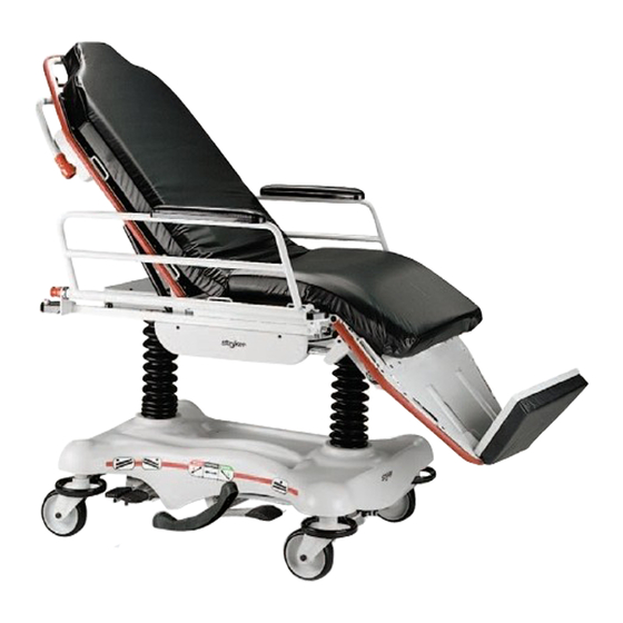
Stretcher chair
Hide thumbs
Also See for 5050:
- Operation manual (116 pages) ,
- Maintenance manual (108 pages) ,
- Operation manual (30 pages)

Related Manuals for Stryker 5050


Summary of Contents for Stryker 5050
- Page 1 M M a a i i n n t t e e n n a a n n c c e e M M a a n n u u a a l l 5050 5051 5050-109-002 Rev A.2 2018/07...
- Page 3 S S y y m m b b o o l l s s Operating instructions General warning Caution No pushing Catalogue number Serial number For US Patents see www.stryker.com/patents CE mark EC REP Manufacturer Safe working load Type B applied part 5050-109-002 Rev A.2...
-
Page 5: Table Of Contents
Siderail adjustment ...............................34 Siderail release knob replacement..........................35 5050 Stationary push bar replacement........................36 Adjustable push bar replacement ...........................37 5050 Pneumatic Fowler backrest adjustment ......................38 5051 Pneumatic Fowler backrest adjustment ......................39 5051 Pneumatic cylinder replacement ........................40 5051 Pneumatic Fowler backrest release handle adjustment..................41 Footrest pan replacement (for stationary or adjustable footrest) ................42... - Page 6 ........................60 Brake drive link assembly - 5050-001-233 ......................61 Pump pedal assembly - 5050-001-080 ........................62 Release pedal assembly, head end, left - 5050-001-245 ..................63 Release pedal assembly, head end, right – 5050-001-244 ..................64 Release pedal assembly, foot end, right - 5050-001-246 ..................65...
- Page 7 Concave head pad - 5050-140-040 ........................116 Ankle restraint strap - 0946-043-001 ........................117 Wrist restraint strap - 0946-044-000 ........................118 Chest restraint strap - 1010-058-000 ........................119 Body restraint strap - 0390-019-000 ........................120 Full restraint strap package - 1010-077-000 ......................
- Page 8 N N o o t t e e - - Provides special information to make maintenance easier or important instructions clearer. 5050-109-002 Rev A.2...
- Page 9 Failure to follow these cleaning instructions may void your warranty. • Do not let the pump piston come out of the jack or damage may occur. • Only use Mobil Aero HFA hydraulic fluid. Using other types of oil may damage hydraulic units. 5050-109-002 Rev A.2...
- Page 10 P P i i n n c c h h p p o o i i n n t t s s 5050-109-002 Rev A.2...
-
Page 11: Expected Service Life
P P r r o o d d u u c c t t d d e e s s c c r r i i p p t t i i o o n n The Stryker Model 5050 and Model 5051 Eye Stretcher Chair is a wheeled stretcher that consists of a platform mounted on a wheeled frame to transport patients in a substantially horizontal position within the interior of a healthcare facility by healthcare professionals or trained representatives of the healthcare facility. -
Page 12: Specifications
24 in. x 74 in. 61 cm x 188 cm Siderails ±45° Standard 10 in. x 31 in. 25 cm x 79 cm Caster diameter/width 6 in. 15 cm Stryker reserves the right to change specifications without notice. 5050-109-002 Rev A.2... - Page 13 C C o o n n t t a a c c t t i i n n f f o o r r m m a a t t i i o o n n Contact Stryker Customer Service or Technical Support at: 1-800-327-0770. Stryker Medical 3800 E. Centre Avenue Portage, MI 49002 To view your operations or maintenance manual online, see https://techweb.stryker.com/. 5050-109-002 Rev A.2...
- Page 14 Have the serial number (A) of your Stryker product available when calling Stryker Customer Service or Technical Support. Include the serial number in all written communication. S S e e r r i i a a l l n n u u m m b b e e r r l l o o c c a a t t i i o o n n D D a a t t e e o o f f m m a a n n u u f f a a c c t t u u r r e e The year of manufacture is the first 2 digits of the serial number.
-
Page 15: Cleaning
The life of the mattress can be affected by an increase in frequency of usage, which might include more frequent cleaning and disinfection. 1. Use a clean, soft cloth to wipe down the entire mattress with a mild soap and water solution to remove foreign material. 5050-109-002 Rev A.2... -
Page 16: Disinfecting
Hard-to-clean spots Use standard household cleansers or vinyl cleansers and a soft bristle brush on troublesome spots or stains. Pre-soak dried-on soil. Laundering Laundering is not recommended. Laundering may substantially decrease the useful life of the mattress. 5050-109-002 Rev A.2... - Page 17 W W A A R R N N I I N N G G - - Always disinfect the mattress between patients. Failure to do so could result in cross-contamination and infection. Recommended disinfectants: • Quaternaries (active ingredient - ammonium chloride) • Phenolic disinfectant (active ingredient - o-phenylphenol) 5050-109-002 Rev A.2...
- Page 18 Failure to follow these cleaning instructions may void your warranty. • Frequent or prolonged exposure to higher concentrations of disinfectant solutions may prematurely age the cover fabric. • The use of accelerated hydrogen peroxides or quaternaries that contain glycol ethers may damage the cover. 5050-109-002 Rev A.2...
-
Page 19: Preventive Maintenance
Remove product from service before you perform the preventive maintenance inspection. Check all items listed during annual preventive maintenance for all Stryker Medical products. You may need to perform preventive maintenance checks more often based on your level of product usage. Service only by qualified personnel. -
Page 20: Service
5 5 0 0 5 5 0 0 Q Q u u i i c c k k r r e e f f e e r r e e n n c c e e r r e e p p l l a a c c e e m m e e n n t t p p a a r r t t s s These parts are currently available for purchase. Call Stryker Customer Service: 1-800-327-0770 for availability and pricing. - Page 21 5 5 0 0 5 5 1 1 Q Q u u i i c c k k r r e e f f e e r r e e n n c c e e r r e e p p l l a a c c e e m m e e n n t t p p a a r r t t s s These parts are currently available for purchase. Call Stryker Customer Service: 1-800-327-0770 for availability and pricing.
- Page 22 Restraint strap, body 0390-019-000 Restraint strap, wrist 0946-044-000 Restraint strap, full package 1010-077-000 Siderail arm pad assembly 5050-026-050 Surgery accessory rail assembly 5051-531-010 Wrist rest assembly, superior 1068-250-000 Wrist rest assembly, temporal 1068-251-000 Wrist rest mounting bracket 5050-050-000 5050-109-002 Rev A.2...
- Page 23 5. Clean the bolt, molded wheel, and the inside of the caster horn (D) to remove any dirt and debris. 6. Make sure that the bearings in the molded wheel spin with ease. 7. Reverse steps to reinstall the caster. 8. Verify proper operation before you return the product to service. 5050-109-002 Rev A.2...
- Page 24 13. Remove the bungee cords. Lower the base hood and secure the V V e e l l c c r r o o ® ® . 14. Verify proper operation before you return the product to service. 5050-109-002 Rev A.2...
-
Page 25: Litter Top Removal
9. Align the holes in the brake rod. Use a hammer to install the supplied groove pin. Drive the pin from the top of the brake/ steer pedal until it is flush with the top of the pedal. 10. Reverse steps to reinstall remaining components. 11. Verify proper operation before you return the product to service. 5050-109-002 Rev A.2... - Page 26 2. Using a 3/32” hex wrench, turn the set screw (B) one full turn counterclockwise to tighten the brake. 3. Using a 3/32” hex wrench, turn the set screw (B) one full turn clockwise to loosen the brake. 4. Verify proper operation before you return the product to service. 5050-109-002 Rev A.2...
- Page 27 6. Lift the litter off of the base and set the litter aside. Take care not to damage the leg section linkages or other litter components. 7. Reverse steps to reinstall the litter top. 8. Verify proper operation before you return the product to service. 5050-109-002 Rev A.2...
- Page 28 17. Keep pressure on the jack spring (B), and use your left hand to place the pump link weldment (C) into the pump pivot assembly (H). Align the other end of the pump link assembly to the hole in the pump piston. 5050-109-002 Rev A.2...
- Page 29 22. Reinstall the base hood and secure it to the V V e e l l c c r r o o ® ® . 23. Reinstall the litter top. 24. Verify proper operation before you return the product to service. 5050-109-002 Rev A.2...
- Page 30 W W A A R R N N I I N N G G - - Always use two people to perform this procedure. 1. Remove the litter top (see Litter top removal (page 23)). 2. Put the jack in the lowest position. 5050-109-002 Rev A.2...
- Page 31 24. Raise the jack to the highest position and lower it again to make sure that the jack works. 25. Install the litter top (see Litter top removal (page 23)). 26. Verify proper operation before you return the product to service. 5050-109-002 Rev A.2...
- Page 32 • Always lower the jack rod to the lowest position to relieve pressure on the pump piston side of the jack to avoid hydraulic fluid loss or product damage when the base plugs are removed. 1. Remove the litter top ( Litter top removal (page 23)). 5050-109-002 Rev A.2...
- Page 33 10. Raise the jack to the highest position. Apply wieight and make sure that the jack holds the position and that there are no hydraulic leaks. 11. Reinstall the litter top. 12. Verify proper operation before you return the product to service. 5050-109-002 Rev A.2...
- Page 34 2. Lift the base hood off of the base, separating the V V e e l l c c r r o o ® ® that holds the hood to the base frame. 3. Lower the jack to the lowest position. 5050-109-002 Rev A.2...
- Page 35 W W A A R R N N I I N N G G - - Always lower the jack rod to the lowest position to relieve pressure on the pump piston side of the jack to avoid hydraulic fluid loss or product damage when the base plugs are removed. 5050-109-002 Rev A.2...
- Page 36 B B a a s s e e l l u u b b r r i i c c a a t t i i o o n n p p o o i i n n t t s s Tools required: • None 1. Grease areas as indicated (A, Figure 8). 5050-109-002 Rev A.2...
- Page 37 11. Insert the latch pivot shaft through the hole in the litter frame and into the latch housing insert. Orient the latch pivot shaft so that the holes in the siderail tube, latch housing insert, and the latch pivot shaft are aligned. Maintain this alignment throughout the siderail installation. 5050-109-002 Rev A.2...
- Page 38 Make sure that the release handle is lubricated. Make sure that the dowel pin through the sides of the siderail is secure. If the siderail will not latch in place: 1. Make sure that the red knob (M) is seated fully when released when the siderail is in both the high and low positions (Figure 9). 5050-109-002 Rev A.2...
- Page 39 8. Apply Loctite 242 to the end of the button head cap screw (K) (removed in step 2). Replace the button head cap screw in the end of the release knob assembly. Using a 3/16” hex wrench, tighten the button head cap screw. 9. Verify proper operation of the siderail before you return the product to service. 5050-109-002 Rev A.2...
- Page 40 4. Using two 9/16” combination wrenches, remove the remaining 3/8” bolt, centerlock nut, and washers on both sides of the push bar. Remove the push bar. 5. Reverse steps to install the supplied push bar. 6. Verify proper operation before you return the product to service. 5050-109-002 Rev A.2...
- Page 41 23. Make sure that the push bar rotates with ease when released and locks in both the up and down positions. 24. Replace the covers and button head cap screws (removed in step 4) on the left side of the push bar. Using a 3/32” hex wrench, tighten the screws. 5050-109-002 Rev A.2...
-
Page 42: Stationary Push Bar Replacement
2. Raise the litter to the highest position. 3. Raise the Fowler backrest to 70 degrees. 4. Remove the push bar (see 5050 Stationary push bar replacement (page 36) or Adjustable push bar replacement (page 37)). 5. Using a 3/32” hex wrench and a 3/8” combination wrench, remove the button head cap screws (A), fiberlock hex nuts (C), and spacers (B) holding the Fowler backrest covers (D (right) and E (left)) located on the under side of the Fowler backrest skin. - Page 43 Squeeze both release handles and pull down on both sides of the Fowler backrest. c. If the pneumatic cylinders still do not release evenly, repeat step four. 7. Verify proper operation before you return the product to service. 5050-109-002 Rev A.2...
- Page 44 9. Using a 5/16” hex wrench and an 11/16”combination wrench , install the nut (B) and bolt (C) on the bottom of the cylinder. 10. Verify proper operation of the cylinder before youreturn the product to service. 5050-109-002 Rev A.2...
-
Page 45: Pneumatic Fowler Backrest Adjustment
4. Tighten the screws on the handle linkage bar and reattach the spring. 5. Adjust the pneumatic cylinders, if necessary (see 5051 Pneumatic Fowler backrest adjustment (page 39)). 6. Verify proper Fowler backrest operation before you return the product to service. 5050-109-002 Rev A.2... - Page 46 9. Reverse steps to reinstall the Nylock lock nut (B), bolt (A), and washers (C) (removed in step 5) on both footrest pivots. 10. Replace the footrest pad and V V e e l l c c r r o o , if necessary. 11. Verify proper operation before you return the product to service. 5050-109-002 Rev A.2...
- Page 47 Tools required: • (2) 9/16” combination wrench • 3/16” hex wrench • 1/2” combination wrench 1. Raise the litter to the highest position. 2. Put the litter in the flat position. 3. Remove the mattress and set aside. 5050-109-002 Rev A.2...
- Page 48 11. Install the washer (D) and hex nut (F) (removed in step 8) to secure the pivot bolt (C) in place. 12. Apply Loctite to the set screw (B; removed in step 7) and reinstall the set screw in the center of the yoke (A). 13. Verify proper operation before you return the product to service. 5050-109-002 Rev A.2...
- Page 49 • Loctite 242 N N o o t t e e - - Locking link replacement part number: 5050-230-042 1. Apply the brakes. Push on the product to make sure that the brakes are working. 2. Raise the litter to the highest position.
- Page 50 9. Reconnect the extension spring. 10. Using regula pliers, grasp the end of the cable and pull firmly to remove any slack. 11. Using two 7/16” combination wrenches, tighten the cable and hex nut (D) (Figure 18). 5050-109-002 Rev A.2...
- Page 51 5 and 6, and 9 through 15. 21. Replace the cover (B) and the screws (A) (removed in step 5). 22. Verify proper operation before you return the product to service. 5050-109-002 Rev A.2...
- Page 52 1. Apply the brakes. Push on the product to make sure that the brakes are working. 2. Raise the litter to the highest position. 3. Place the product into dependent mode. 4. Lower the Fowler backrest to the lowest position. 5050-109-002 Rev A.2...
-
Page 53: Leg Section Locking Link Replacement
F F i i g g u u r r e e 1 1 9 9 – – L L e e g g s s e e c c t t i i o o n n c c a a b b l l e e r r e e p p l l a a c c e e m m e e n n t t 23. Complete the locking link adjustment (see Locking link adjustment (page 46)) before you return the product to service. 5050-109-002 Rev A.2... - Page 54 To install the mattress, slide the pockets on the foot end back over the sliding tabs. Place the mattress on the rest of the litter surface. Press firmly on the Fowler backrest and midsection to secure the V V e e l l c c r r o o strips. 5050-109-002 Rev A.2...
- Page 55 B B a a s s e e a a s s s s e e m m b b l l y y - - M M o o d d e e l l 5 5 0 0 5 5 0 0 5050-001-200 Rev T (Reference only)
- Page 56 Q Q u u a a n n t t i i t t y y 0042-013-000 Collar 0042-020-000 Collar 0715-001-011 Brake cushion 0715-001-061 Caster brake assembly 0715-001-092 Pump pedal shaft 0715-001-094 Compression spring 0715-001-133 Jack spring collar 0715-001-140 Tube 0715-001-150 Roller brake adjuster assembly 3001-200-052 Ground chain 5050-109-002 Rev A.2...
- Page 57 Socket head cap screw 5050-001-010 Base weldment 5050-001-080 Pump pedal assembly 5050-001-090 Pump pivot assembly 5050-001-100 Pump link weldment 5050-001-110 Pump tube weldment 5050-001-218 Release sleeve weldment, foot end 5050-001-222 Linkage rod, head end 5050-001-223 Release linkage, foot end 5050-109-002 Rev A.2...
- Page 58 Socket head cap screw 0081-245-000 Flange bearing 0715-001-134 Bellows 1210-201-153 Butterfly “V” pedal 0011-262-000 Washer 0011-004-000 Washer 1210-201-335 Label, brake 1210-201-336 Label, steer 0715-001-333 Stop sleeve 0013-018-000 External tooth lock washer 0029-007-000 Dual lock 0029-009-000 Dual lock 5050-109-002 Rev A.2...
- Page 59 B B a a s s e e a a s s s s e e m m b b l l y y - - M M o o d d e e l l 5 5 0 0 5 5 1 1 5051-001-200 Rev E (Reference only) 5050-109-002 Rev A.2...
- Page 60 N N a a m m e e Q Q u u a a n n t t i i t t y y 0042-013-000 Collar 0042-020-000 Collar 0715-001-011 Brake cushion 0715-001-061 Caster brake assembly 0715-001-092 Pump pedal shaft 0715-001-094 Compression spring 5050-109-002 Rev A.2...
- Page 61 Hex head cap screw 0038-211-000 Compression spring 0038-234-000 Compression spring 0004-039-000 Socket head cap screw 0004-300-000 Socket head cap screw 0004-085-000 Socket head cap screw 5050-001-010 Base weldment 5050-001-080 Pump pedal assembly 5050-001-090 Pump pivot assembly 5050-001-100 Pump link weldment 5050-109-002 Rev A.2...
- Page 62 Socket head cap screw 0081-245-000 Flange bearing 0715-001-134 Bellows 1210-201-153 Butterfly “V” pedal 0011-262-000 Washer 0011-004-000 Washer 1210-201-335 Label, brake 1210-201-336 Label, steer 0715-001-333 Stop sleeve 0013-018-000 External tooth lock washer 0029-007-000 Dual lock 0029-009-000 Dual lock 5050-109-002 Rev A.2...
- Page 63 N N a a m m e e Q Q u u a a n n t t i i t t y y 0715-201-062 Threaded stud assembly 0014-004-000 Nylon washer 0715-001-180 Bearing, cam 0028-008-000 External retaining ring 5050-109-002 Rev A.2...
- Page 64 N N a a m m e e Q Q u u a a n n t t i i t t y y 0715-301-221 Brake cam 0016-059-000 Hex nut 5050-001-228 Brake cam link 0008-021-000 Socket head shoulder bolt 5050-109-002 Rev A.2...
- Page 65 N N u u m m b b e e r r N N a a m m e e Q Q u u a a n n t t i i t t y y 5050-001-226 Brake drive link 5050-001-232 Rod end bearing 5050-109-002 Rev A.2...
- Page 66 N N a a m m e e Q Q u u a a n n t t i i t t y y 0715-201-126 Pump pedal 5050-001-082 Pump pedal assembly weldment 5050-001-093 Spherical bearing 0026-143-000 Groove pin 5050-109-002 Rev A.2...
- Page 67 Q Q u u a a n n t t i i t t y y 0721-040-025 Pedal 5050-001-211 Control release pedal, head end, left N N o o t t e e - - Apply plastic adhesive to the mating surfaces of item A prior to assembly. 5050-109-002 Rev A.2...
- Page 68 Q Q u u a a n n t t i i t t y y 0721-040-025 Pedal 5050-001-220 Control release pedal, head end, right N N o o t t e e - - Apply plastic adhesive to the mating surfaces of item A prior to assembly. 5050-109-002 Rev A.2...
- Page 69 Q Q u u a a n n t t i i t t y y 0721-040-025 Pedal 5050-001-208 Control release pedal, foot end, left N N o o t t e e - - Apply plastic adhesive to the mating surfaces of item A prior to assembly. 5050-109-002 Rev A.2...
- Page 70 Q Q u u a a n n t t i i t t y y 0721-040-025 Pedal 5050-001-210 Control release pedal, foot end, right N N o o t t e e - - Apply plastic adhesive to the mating surfaces of item A prior to assembly. 5050-109-002 Rev A.2...
- Page 71 N N a a m m e e Q Q u u a a n n t t i i t t y y 0026-013-000 Spring pin 5050-001-013 Brake pivot weldment 5050-001-014 Actuator weldment 5050-001-265 Actuator arm 5050-001-280 Steer lock arm weld 0014-080-000 Washer 5050-109-002 Rev A.2...
- Page 72 N N a a m m e e Q Q u u a a n n t t i i t t y y 0026-013-000 Spring pin 5050-001-013 Brake pivot weldment 5050-001-014 Actuator weldment 5050-001-265 Actuator arm 0014-080-000 Washer 5050-109-002 Rev A.2...
-
Page 73: In. Molded Wheel Assembly
Q Q u u a a n n t t i i t t y y 0016-060-000 Hex nut 0003-205-000 Hex cap screw 0715-003-096 Hex cap screw 5050-002-010 5.75 in. molded wheel assembly (page 5050-002-030 Caster assembly 0011-310-000 Washer 5050-109-002 Rev A.2... - Page 74 Q Q u u a a n n t t i i t t y y 0016-060-000 Hex nut 0003-205-000 Hex cap screw 0715-003-096 Hex cap screw 5.75 in. molded wheel assembly (page 5050-002-010 5050-002-031 Caster Assembly 0011-310-000 Washer 5050-109-002 Rev A.2...
- Page 75 5 5 . . 7 7 5 5 i i n n . . m m o o l l d d e e d d w w h h e e e e l l a a s s s s e e m m b b l l y y 5050-002-010 Rev A (Reference only)
-
Page 76: Jack Base Assembly
Gasket 0390-001-244 Base gasket 0390-002-139 Retaining ring 0715-001-331 Piston end 0715-001-340 Jack cap assembly 0715-001-422 Reservoir 0926-020-161 Parker packing 0926-030-162 Wear ring 5050-090-017 Label, jack assembly 5050-270-020 Actuator cylinder 5050-370-030 Actuator 5050-270-100 Jack base assembly (page 74) 5050-109-002 Rev A.2... - Page 77 N N u u m m b b e e r r N N a a m m e e Q Q u u a a n n t t i i t t y y 0715-001-320 Jack screen 0921-001-252 Label, serial number 5050-109-002 Rev A.2...
- Page 78 J J a a c c k k b b a a s s e e a a s s s s e e m m b b l l y y 5050-270-100 Rev J (Reference only) Torque item F to 50 ±...
- Page 79 Q Q u u a a n n t t i i t t y y 0715-001-328 Piston wear ring 0715-001-400 O-ring back up 0715-200-316 Pump cylinder 0715-201-318 Pump piston 0715-201-327 Cylinder wear ring 0014-050-000 Washer 0045-110-000 O-ring 5050-109-002 Rev A.2...
- Page 80 5050-090-015 Label, weight capacity Note: The specification label (5050-090-015), and the warning labels (5050-090-006 and 5050-090-007) are critical to the safe operation of the stretcher chair. If they are not present and in good condition, they must be replaced. 5050-109-002 Rev A.2...
- Page 81 Emergency 1010-900-215 Radiology 1010-900-250 P.A.C.U. 1010-900-220 Nuclear medicine 1010-900-255 Transport 1010-900-225 Ambulatory surgery 1010-900-260 Surgery 1010-900-230 G.I. lab 1010-900-265 Extended stay 1010-900-235 Cath. lab 1010-900-270 Maternity 1010-900-240 Same day surgery 1010-900-275 Endoscopy 1010-900-245 Cardio 1010-900-280 Ultrasound 1010-900-285 5050-109-002 Rev A.2...
- Page 82 M M i i d d s s e e c c t t i i o o n n a a s s s s e e m m b b l l y y 5050-031-001 Rev J (Reference only)
- Page 83 N N a a m m e e Q Q u u a a n n t t i i t t y y 7900-001-102 V V e e l l c c r r o o ® pile 5050-031-040 Spring mount 5050-109-002 Rev A.2...
- Page 84 5 5 0 0 5 5 0 0 F F o o w w l l e e r r b b a a c c k k r r e e s s t t a a s s s s e e m m b b l l y y 5050-033-001 Rev J (Reference only)
- Page 85 5050-109-002 Rev A.2...
- Page 86 Washer 0015-037-000 Hex jam nut 0015-050-000 Hex nut 0016-036-000 Nylock hex nut 0016-014-000 Fiberlock hex nut 0016-028-000 Nylock hex nut 0016-090-000 Nylock hex nut 0021-125-000 Set screw 0021-119-000 Set screw 0021-126-000 Set screw 0025-038-000 Dome head rivet 5050-109-002 Rev A.2...
- Page 87 Spacer 5050-033-019 Trip bar link 5050-090-006 Label, warning, head end/foot end 7900-001-102 V V e e l l c c r r o o ® pile 5050-133-011 Push bar hinge 8839-793-700 Cap screw 0016-036-000 Nylock hex nut 5050-109-002 Rev A.2...
- Page 88 5 5 0 0 5 5 1 1 F F o o w w l l e e r r b b a a c c k k r r e e s s t t a a s s s s e e m m b b l l y y 5051-132-010 Rev E (Reference only) 5050-109-002 Rev A.2...
- Page 89 Q Q u u a a n n t t i i t t y y 1069-031-011 Shoulder rivet 1069-031-012 Barrel nut 1069-031-031 Short handle adjustment link 1210-031-103 Pivot tab 5050-531-032 Long handle adjustment link 5050-531-041 Handle pivot bracket, left 5050-531-046 Handle pivot bracket, right 5050-109-002 Rev A.2...
- Page 90 Head piece assembly 0011-180-000 Washer 0014-009-000 Washer 0014-019-000 Washer 0014-020-000 Washer 0014-087-000 Washer 3001-300-099 Fowler modified bushing 0038-436-000 Extension spring 5050-633-010 Fowler weldment 7900-001-102 Velcro® pile 2.67 ft 1069-060-091 Label, Fowler release, right 1069-060-092 Label, Fowler release, left 5050-109-002 Rev A.2...
- Page 91 D D u u a a l l a a r r t t i i c c u u l l a a t t i i n n g g h h e e a a d d p p i i e e c c e e - - 1 1 0 0 6 6 9 9 - - 1 1 3 3 3 3 - - 0 0 2 2 0 0 Rev D (Reference Only) 5050-109-002 Rev A.2...
- Page 92 1069-133-030 Neck weldment 1069-133-040 Head weldment 1069-133-057 Head bracket weldment, right 1069-133-058 Head bracket weldment, left 1069-133-073 Threaded gear 1069-133-075 Headpiece cover 1069-133-076 Gear housing 1069-133-083 Head shaft 1069-133-084 Neck shaft 1069-133-085 Neck spacer 1069-133-088 Head spacer 5050-109-002 Rev A.2...
- Page 93 Q Q u u a a n n t t i i t t y y 1069-133-100 Link weldment 1069-133-110 Handle weldment, right 1069-133-115 Handle weldment, left 7900-001-102 V V e e l l c c r r o o ® pile .71 ft 1069-133-121 Handle torsion spring 5050-109-002 Rev A.2...
- Page 94 I I n n d d e e p p e e n n d d e e n n t t l l e e g g / / s s t t a a t t i i o o n n a a r r y y f f o o o o t t s s e e c c t t i i o o n n a a s s s s e e m m b b l l y y 5050-037-011 Rev B (Reference only)
- Page 95 N N u u m m b b e e r r N N a a m m e e Q Q u u a a n n t t i i t t y y 0081-247-000 Ball bearing 0938-001-401 Collar 0946-035-025 Liner 1010-031-077 Gas Cylinder 5050-109-002 Rev A.2...
-
Page 96: Locking Link Assembly
0042-022-000 Locking collar 5050-030-001 Side enclosure, right 5050-030-002 Side enclosure, left 5050-030-007 Foot skin 5050-230-042 Locking link assembly ( Locking link assembly (page 98)) 5050-030-028 Side enclosure bracket 5050-030-031 Foot end bumper channel 5050-030-032 Foot section cover 5050-109-002 Rev A.2... - Page 97 Socket head shoulder screw 5050-032-065 Foot rest tape 0003-025-000 Hex head cap screw 0023-256-000 Pan head sheet metal screw Cable routing detail: Route cables as shown. Patient right side to be routed under butt section, but over bellows as indicated. 5050-109-002 Rev A.2...
- Page 98 I I n n d d e e p p e e n n d d e e n n t t l l e e g g / / a a d d j j u u s s t t a a b b l l e e f f o o o o t t s s e e c c t t i i o o n n a a s s s s e e m m b b l l y y - - 5 5 0 0 5 5 0 0 - - 0 0 3 3 2 2 - - 0 0 0 0 1 1 Rev K (Reference only) 5050-109-002 Rev A.2...
- Page 99 N N a a m m e e Q Q u u a a n n t t i i t t y y 0081-247-000 Ball bearing 0938-001-401 Collar 0946-035-025 Liner 1010-031-077 Gas cylinder 1068-234-036 Handle grip 0011-379-000 Steel washer 0014-019-000 Nylon washer 5050-109-002 Rev A.2...
- Page 100 5050-230-042 Locking link assembly (page 98) 5050-030-028 Side enclosure bracket 5050-030-031 Foot end bumper channel 5050-030-032 Foot section cover 5050-032-010 Independent leg/adjustable foot weldment 5050-032-012 Swivel weldment 5050-032-015 Cable bracket weldment 5050-032-017 Magnet plate 5050-032-018 Spring rocker 5050-109-002 Rev A.2...
- Page 101 5050-090-006 Label, warning 5050-090-007 Label, warning, foot rest 0007-034-000 Truss head machine screw 0008-044-000 Socket head shoulder screw 5050-032-065 Foot rest tape 0003-025-000 Hex head cap screw 0023-256-000 Pan head sheet metal screw 0946-001-060 Label, Stryker logo 5050-109-002 Rev A.2...
- Page 102 L L o o c c k k i i n n g g l l i i n n k k a a s s s s e e m m b b l l y y 5050-230-042 Rev A (Reference only)
- Page 103 N N o o n n - - t t r r a a n n s s f f e e r r s s i i d d e e r r a a i i l l a a s s s s e e m m b b l l y y 5050-026-070 Rev G (Reference only)
- Page 104 Latch housing insert 5050-026-003 Latch pivot shaft 5050-026-037 Release knob assembly, left 5050-126-051 Transfer siderail assembly, left 5050-126-052 Transfer siderail assembly, right 5050-026-080 Board support assembly – 5050-026- 080 (page 101) 5050-091-003 Label, siderail release 0014-021-000 Nylon washer 5050-109-002 Rev A.2...
- Page 105 Q Q u u a a n n t t i i t t y y 0008-015-000 Socket head shoulder bolt 0033-002-000 Ball knob 0038-368-000 Compression spring 1010-024-014 Label, warning 5050-026–081 Support block 5050-026-082 Support arm *(D for EU)) 1010-091-014 Euro warning label 5050-109-002 Rev A.2...
- Page 106 A A d d j j u u s s t t a a b b l l e e p p u u s s h h b b a a r r a a s s s s e e m m b b l l y y 5050-139-010 Rev B (Reference only)
- Page 107 S S t t a a t t i i o o n n a a r r y y p p u u s s h h b b a a r r a a s s s s e e m m b b l l y y 5050-138-010 Rev A (Reference only)
-
Page 108: Accessories
A A c c c c e e s s s s o o r r i i e e s s These accessories may be available for use with your product. Confirm availability for your configuration or region. Call Stryker Customer Service: 1-800-327-0770. N N a a m m e e... - Page 109 N N a a m m e e Q Q u u a a n n t t i i t t y y 0390-003-056 Knob 0390-003-053 Double IV assembly 0393-003-043 Tube assembly 0004-496-000 Socket head cap screw 0390-125-011 Label, IV pole removable 5050-109-002 Rev A.2...
-
Page 110: Tethered Iv Pole Trough Assembly
T T e e t t h h e e r r e e d d I I V V p p o o l l e e a a s s s s e e m m b b l l y y - - 5 5 0 0 5 5 0 0 - - 0 0 7 7 5 5 - - 0 0 0 0 0 0 5050-075-001 Rev A (Reference only) - Page 111 T T e e t t h h e e r r e e d d I I V V p p o o l l e e t t r r o o u u g g h h a a s s s s e e m m b b l l y y 5050-075-005 Rev - (Reference only)
- Page 112 Q Q u u a a n n t t i i t t y y 0004-495-000 Socket head cap screw 0021-016-000 Set screw 0741-047-014 Retainer 0938-001-305 Pole socket assembly 0938-001-308 Pole assembly 1211-117-016 Plastic knob 1211-117-020 Cable assembly 5050-109-002 Rev A.2...
- Page 113 W W r r i i s s t t r r e e s s t t b b r r a a c c k k e e t t a a s s s s e e m m b b l l y y - - 5 5 0 0 5 5 0 0 - - 0 0 5 5 0 0 - - 0 0 0 0 0 0 5050-050-001 Rev A (Reference only)
- Page 114 Female insert knob 0004-371-000 Socket head cap screw 1068-050-055 Support bar wrist rest weldment 1068-250-041 Wrist rest wedge bolt 1068-250-042 Wrist rest lock wedge 1068-250-050 Base tube weldment 1068-252-055 Support bar wrist rest casting 1068-290-050 Label, specification 5050-109-002 Rev A.2...
- Page 115 Acorn nut 0024-054-000 Female insert knob 0004-371-000 Socket head cap screw 1068-051-050 Temporal tube weldment 1068-250-041 Wrist rest wedge bolt 1068-250-042 Wrist rest lock wedge 1068-250-050 Base tube weldment 1068-252-055 Support bar wrist rest casting 1068-290-051 Label, specification 5050-109-002 Rev A.2...
- Page 116 1068-168-050 Drape support weldment 1068-068-043 Oxygen tube cap 1068-268-042 Oxygen hose receptacle 1068-068-041 Oxygen supply line 1068-090-068 Label, specification 1066-085-013 Goose neck 1068-168-015 Oxygen latch 0026-172-000 Roll pin 0014-007-000 Flat washer 0011-063-000 Washer 0030-067-000 Grommet 0052-324-000 Spacer 5050-109-002 Rev A.2...
- Page 117 N N a a m m e e Q Q u u a a n n t t i i t t y y 1068-066-042 Bar/rail 5050-531-008 Spacer 0003-068-000 Hex head cap screw 0004-326-000 Socket head cap screw 5050-109-002 Rev A.2...
- Page 118 1060-001-154 Split ring 1060-001-155 Ball post 1060-001-159 Leg support bar 1068-056-013 Armboard cover 1068-056-015 Armboard 1068-056-016 Restraint strap assembly 8812-670-000 7900-001-102 V V e e l l c c r r o o ® pile 4 in. 5050-109-002 Rev A.2...
- Page 119 1060-001-155 Ball post 1060-001-159 Leg support bar 1068-056-013 Armboard cover 1068-056-015 Armboard 1068-056-016 Restraint strap assembly 8812-670-000 7900-001-102 V V e e l l c c r r o o ® pile 4 in. 1068-054-010 Direct clamp 5050-109-002 Rev A.2...
- Page 120 Q Q u u a a n n t t i i t t y y 5050-140-041 Concave head foam 5050-140-042 Concave headrest cover assembly 7900-001-102 V V e e l l c c r r o o ® 5050-109-002 Rev A.2...
- Page 121 A A n n k k l l e e r r e e s s t t r r a a i i n n t t s s t t r r a a p p - - 0 0 9 9 4 4 6 6 - - 0 0 4 4 3 3 - - 0 0 0 0 1 1 Rev F (Reference Only) 5050-109-002 Rev A.2...
- Page 122 W W r r i i s s t t r r e e s s t t r r a a i i n n t t s s t t r r a a p p - - 0 0 9 9 4 4 6 6 - - 0 0 4 4 4 4 - - 0 0 0 0 0 0 Rev B (Reference only) N N u u m m b b e e r r N N a a m m e e 0946-044-001 Wrist restraining strap 5050-109-002 Rev A.2...
- Page 123 C C h h e e s s t t r r e e s s t t r r a a i i n n t t s s t t r r a a p p - - 1 1 0 0 1 1 0 0 - - 0 0 5 5 8 8 - - 0 0 0 0 0 0 Rev E (Reference only) N N u u m m b b e e r r N N a a m m e e 0390-019-001 Restraining strap, long 0390-019-002 Restraining strap, short 5050-109-002 Rev A.2...
- Page 124 B B o o d d y y r r e e s s t t r r a a i i n n t t s s t t r r a a p p - - 0 0 3 3 9 9 0 0 - - 0 0 1 1 9 9 - - 0 0 0 0 0 0 Rev D (Reference only) N N u u m m b b e e r r N N a a m m e e 0390-019-001 Restraining strap, long 0390-019-002 Restraining strap, short 5050-109-002 Rev A.2...
- Page 125 Rev C (Reference only) N N u u m m b b e e r r N N a a m m e e 0390-019-000 Body restraint 0946-043-001 Ankle restraint strap assembly 0946-044-001 Wrist restraint 1010-058-000 Chest restraint 5050-109-002 Rev A.2...
- Page 126 Stryker Medical 3800 E. Centre Avenue Portage, MI 49002 5050-109-002 Rev A.2 2018/07 WCR: AA.13...
Need help?
Do you have a question about the 5050 and is the answer not in the manual?
Questions and answers