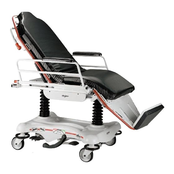
Stryker 5050 Maintenance Manual
Eye / stretcher chair
Hide thumbs
Also See for 5050:
- Maintenance manual (126 pages) ,
- Operation manual (116 pages) ,
- Maintenance manual (108 pages)
Table of Contents

Related Manuals for Stryker 5050


Summary of Contents for Stryker 5050
- Page 1 5050 Stretcher Chair 5051 Eye Stretcher Chair Maintenance Manual For 5050 stretchers with serial numbers of 9711034001 and above For 5051 stretchers with serial numbers of 9901034565 and above For Parts or Technical Assistance 800–327–0770...
-
Page 2: Table Of Contents
Table of Contents Introduction Specifications ................Warning / Caution / Note Definition . - Page 3 ..............Fowler Assembly (5050) .
- Page 4 Table of Contents Assembly Drawings and Parts Lists (Continued) Heel Stirrup Bracket Assembly ............Wrist Rest Assembly .
-
Page 5: Introduction
Introduction INTRODUCTION This manual is designed to assist you with the maintenance of the model 5050 and model 5051 Stretcher Chair. Read it thoroughly before using the equipment or beginning any maintenance on it. SPECIFICATIONS Maximum Weight Capacity 400 pounds Overall Stretcher Length/Width 76”/30”... -
Page 6: Cleaning
If these types of products are used to clean Stryker patient handling equipment, measures must be taken to insure the stretchers are rinsed with clean water and thoroughly dried following cleaning. Failure to properly rinse and dry the stretchers will leave a cor- rosive residue on the surface of the stretcher, possibly causing premature corrosion of critical components. -
Page 7: Checklist
Preventative maintenance should be performed at a minimum of annually. A preventative maintenance pro- gram should be established for all Stryker Medical equipment. Preventative maintenance may need to be performed more frequently based on the usage level of the product. -
Page 8: Replacement Parts List
5050 Replacement Parts PART NAME PART NUMBER Arm Board Support Assembly ......... - Page 9 ......... 5050–26–80 Brake Adjuster Assembly .
- Page 10 ..........5050–26–50 Surgery Accessory Rail Assembly .
-
Page 11: Service Information
6. Using an Allen wrench and a 1/2” wrench, remove the nylon lock nut underneath the pump piston. 7. Using a straight screwdriver and pump spring compression tool (p/n 5050–500–70) compress the pump spring and pry the pump link and socket head fastener out of the pump cylinder. -
Page 12: Jack Pump Piston Replacement
6. Using an Allen wrench, and a 1/2” wrench, remove the nylon lock nut underneath the pump piston. 7. Using a straight screwdriver and pump spring compression tool (p/n 5050–500–70), compress the pump spring and pry the pump link and socket head fastener out of the pump cylinder. - Page 13 Service Information JACK PUMP PISTON REPLACEMENT (CONTINUED) 14. With the pump pedal in the full–up position, insert the pump link into the pump pivot assembly and align the hole in the end of the pump link to the hole in the pump piston on the jack. Pull out or push in on the pump piston as required.
-
Page 14: Hydraulic Check Valve Replacement
ITEM PART NO. PART NAME 45–966 O–Ring 45–967 O–Ring 390–2–134 Conical Comp. Spring 715–1–301 Base Plug 715–1–309 Valve Plug 715–1–341 Poppet 715–100–325 Pump Replacement Ass’y 926–20–153 Check Valve 926–20–154 Seal 926–20–156 Seal 1210–70–9 Valve Assembly 5050–70–50 P.C. Valve... -
Page 15: Checking Hydraulic Fluid Level
4. The hydraulic fluid should be visible at the bottom of the fill hole. If it is not, add Mobil Aero HFA hydraulic fluid (Stryker part number 2020–70–475) until the fluid is visible at the bottom of the fill hole. Replace the fill plug. -
Page 16: Adjustable Pressure Compensated (P.c.) Valve Replacement
Service Information ADJUSTABLE PRESSURE COMPENSATED (P.C.) VALVE REPLACEMENT WARNING To avoid personal injury or damage to the stretcher, always remove the litter and the base hood before begin- ning service on the jacks. Lower the jack rod completely to relieve the pressure on the pump piston side of the jack. -
Page 17: Jack Descent Rate Adjustment
Service Information JACK DESCENT RATE ADJUSTMENT Required Tools: Bungee Cords Adjustment Procedure: 1. Pump the litter up to full height 2. Lift the base hood, separating the Velcro holding it to the base frame. 3. The adjustable descent valve is located on the base of the jack and has a blue knob on the end. To adjust, loosen the silver locking ring by turning it counterclockwise. -
Page 18: Brake/Steer Pedal Replacement
Service Information BRAKE/STEER PEDAL REPLACEMENT Required Tools: Two (2) 7/16” Wrenches 3/16” Drive Pin Loctite 409 or Equivalent Hammer 3/8” Box End Wrench Bungee Cords Replacement Procedure: NOTE It may require two people to safely perform this procedure. 1. Apply the brakes, if possible, with the remaining good brake/steer pedal. If this is not possible, have someone assist you with the following: Using a large wrench or pry tool, push down on the brake bar (compressing the spring) and manually move the molded plastic brake cam over to the brake position at both ends of the base. -
Page 19: Caster Maintenance
Service Information CASTER MAINTENANCE Required Tools: 5/8” Wrench 11/16” Wrench MAINTENANCE PROCEDURE 1. Using the 5/8” wrench and the 11/16” wrench, remove the centerlock nut (item A) from the through bolt (item B) for the caster wheel. 2. Support the corner of the Stretcher Chair where the wheel is being removed and remove the through bolt (item B) and the molded wheel (item C) . -
Page 20: Base Lubrication Points
Service Information BASE LUBRICATION POINTS Grease areas as shown. Grease two places. BRAKE ADJUSTMENT Required Tools: 3/32” Hex Allen Wrench Pry Bar Thread ”Locktite”... -
Page 21: Siderail Replacement
Service Information SIDERAIL REPLACEMENT (TRANSFER/NON–TRANSFER) Required Tools: Hammer 1/4” Drive Pin 3/16” Hex Allen Wrench Loctite 242 Pliers Replacement Procedure: 1. Apply the Stretcher Chair’s brakes. Raise the litter to full height and put the Fowler up. 2. Rotate the siderail to a horizontal position and support it. 3. -
Page 22: Siderail Adjustment
Service Information SIDERAIL ADJUSTMENT Required Tools: 3/16” Hex Allen Wrench Loctite 242 WARNING Proper siderail latching is necessary for patient and user safety. Check the siderails frequently to ensure both sides latch securely in both the upright and down positions. In addition, check for proper lubrication of the release handle and for secure dowel pins through the sides of the siderails. -
Page 23: Adjustable Push Bar Replacement
Service Information ADJUSTABLE PUSH BAR REPLACEMENT Required Tools: (2) 9/16” Wrenches (2) 1/8” Hex Allen Wrenches 3/32” Hex Allen Wrench Replacement Procedure: 1. Apply the brakes, raise the litter to full height and raise the Fowler to 90_. 2. Use the 3/32” hex Allen wrench to remove the button head cap screws from the small plastic covers at the ends of the left side of the push bar. -
Page 24: Stationary Push Bar Replacement
Service Information STATIONARY PUSH BAR REPLACEMENT Required Tools: (2) 9/16” Wrenches 3/16” Hex Allen Wrench 1/2” Wrench 3/32” Hex Allen Wrench Replacement Procedure: 1. Apply the brakes, raise the litter to full height and raise the Fowler to 90_. 2. Using the 3/32” hex Allen wrench, remove the button head cap screws from the small plastic covers at each end of the push bar. -
Page 25: Pneumatic Fowler Adjustment
3/8” Box End Wrench Adjustment Procedure: 1. Refer to drawing 5050–33–1 (page 56 & 57) for part reference. 2. Apply the Stretcher Chair brakes. For easier access, move Fowler to 70_ or higher. 3. Remove the push bar (see page 22 or 23). -
Page 26: Pneumatic Fowler Adjustment
Service Information 5050 PNEUMATIC FOWLER ADJUSTMENT (CONTINUED) 9. When the Fowler is properly adjusted, replace the washers and hex nuts to secure the pivot bolts. 10. Using thread Loctite, reinstall set screws (item Z). 11. Replace the left and right Fowler covers (items AN & AP) and reinstall the cover fasteners (item A), nuts (item S) and spacers (item AF). -
Page 27: 5051 Pneumatic Fowler Release Handle Adjustment
Service Information 5051 PNEUMATIC FOWLER RELEASE HANDLE ADJUSTMENT Required Tools: #2 Phillips Screwdriver Adjustment Procedure: 1. Apply the stretcher brakes. 2. Loosen the two Phillips head screws on the handle linkage. Release the handle tension spring on the patient’s left side. 3. -
Page 28: Articulating Head Piece Adjustment
Service Information ARTICULATING HEAD PIECE ADJUSTMENT Required Tools: #2 Phillips Screwdriver 17/16” Socket and Ratchet Standard Screwdriver Adjustment Procedure: 1. If the neck section is binding, the (patient) left handle needs adjustment. If the head section is binding, the (patient) right handle needs ad- justment. -
Page 29: Dependent Leg Section Rigid Link Replacement
Service Information DEPENDENT LEG SECTION RIGID LINK REPLACEMENT Required Tools: (2) 9/16” Wrenches 1/2” Wrench 3/16” Hex Allen Wrench Replacement Procedure: 1. Pump the litter to full height, lower the Fowler so that stretcher chair is flat and apply brakes. 2. -
Page 30: Dependent Leg Section Frame Replacement
1. Set the brakes, raise litter to full height, put stretcher chair in flat position and put unit in slight Trendelen- burg (head down) for access to the cylinder. 2. Refer to drawing 5050–37–1 on pages 74–77 for part reference. 3. Be sure the independent leg section handles are pointed toward the head end of the stretcher chair. -
Page 31: Independent Leg Locking Linkage Adjustment
1. Raise litter to full height, put it into dependent mode, put the Fowler all the way down, and set the brakes. 2. Refer to drawings 5050–37–1 on pages 74–77 and 5050–30–42 on page 82 for part reference. 3. Use the 1/4” nut driver to remove the self–tapping screws (item AH on page 76) securing the plastic link- age cover (item BH on page 76) and remove the cover. -
Page 32: Independent Leg Section Locking Link Replacement
8. Starting at the head end of the unit, install the replacement locking linkage being sure that the orientation of the linkage is correct (refer to drawing 5050–32–1 page 79). The cable mount side of the locking link- age should be on the inside of the stretcher chair and the extension spring should be toward the bottom of the linkage. -
Page 33: Independent Leg Section Cable Replacement
1/4” Nut Driver Replacement Procedure: 1. Refer to drawings 5050–32–1 on page 78–81, and 5050–30–42 on page 82 for part references. 2. Raise litter to full height, apply brakes, put unit into dependent mode and lower Fowler completely. 3. Put the unit into independent mode. Be sure that the red handles on the leg section are pointing toward the head end of the stretcher chair. -
Page 34: Independent Leg Section Handle Adjustment
1/4” Wrench Adjustment Procedure: 1. Refer to drawing 5050–32–1 on page 78–81 for part reference. 1. Raise the litter to full height, apply the brakes and raise the leg section fully to the horizontal position. 2. Rotate the red independent leg section handles so that they point down toward the floor. - Page 35 Assembly part number 5050–1–200 & 5051–1–200 FOOT END BASE WELDMENT SHOWN UPSIDE DOWN HEAD END...
- Page 36 FOOT END HEAD END...
-
Page 37: Base Assembly
Base Assembly... - Page 38 Base Assembly...
-
Page 39: Base Assembly
Compression Spring 4–300 H. Soc. But. Hd. Cap Scr. 1 715–1–133 Jack Spring Collar 4–85 Soc. Hd. Cap Screw 715–1–140 Vinyl Tube 5050–1–10 Base Weldment (page 39) Brake Adjuster (page 41) Pump Pedal Ass’y 715–1–156 Ground Chain 5050–1–90 Pump Pivot Ass’y 715–1–158... -
Page 40: Brake Adjuster Assembly
715–201–150 Brake Adjuster Assembly Item Part No. Part Name Qty. 715–1–180 Cam Bearing 715–201–62 Threaded Stud Assembly 14–4 Nylon Washer 28–8 External Retaining Ring... -
Page 41: Brake Cam Assembly
Item Part No. Part Name Qty. 715–301–221 Brake Cam 16–59 Hex Nut 5050–1–228 Brake Cam Link 8–21 Socket Hd. Shoulder Bolt 5050–1–233 Brake Drive Link Assembly Item Part No. Part Name Qty. 5050–1–226 Brake Drive Link 5050–1–232 Rod End Bearing... -
Page 42: Pump Pedal Assembly
5050–1–80 Pump Pedal Assembly Item Part No. Part Name Qty. 715–201–126 Slip–On Pedal Pad 5050–1–82 Pump Pedal Weldment 5050–1–93 Spherical Bearing 26–143 Groove Pin... -
Page 43: Release Pedal Assembly
5050–1–244 Release Pedal Assembly, Head End, Right Item Part No. Part Name Qty. 721–40–25 Rubber Pedal 5050–1–220 Release Pedal, Head, Right 5050–1–245 Release Pedal Assembly, Head End, Left Item Part No. Part Name Qty. 721–40–25 Rubber Pedal 5050–1–211 Release Pedal, Head, Left NOTE Apply plastic adhesive to the mating surfaces of item A prior to assembly. -
Page 44: Release Pedal Assembly
5050–1–246 Release Pedal Assembly, Foot End, Right Item Part No. Part Name Qty. 721–40–25 Rubber Pedal 5050–1–208 Release Pedal, Foot, Right 5050–1–247 Release Pedal Assembly, Foot End, Left Item Part No. Part Name Qty. 721–40–25 Rubber Pedal 5050–1–210 Release Pedal, Foot, Left NOTE Apply plastic adhesive to the mating surfaces of item A prior to assembly. -
Page 45: Brake Actuator Assembly
Foot End Brake Actuator Assembly Assembly part number 5050–1–260 (reference only) Item Part No. Part Name Qty. 26–13 Spring Pin 5050–1–13 Brake Pivot Weldment 5050–1–14 Actuator Weldment 5050–1–265 Actuator Arm 5050–1–280 Steerlock Arm Weldment 14–80 Nylon Washer... -
Page 46: Brake Actuator Assembly
Head End Brake Actuator Assembly Assembly part number 5050–1–261 (reference only) Item Part No. Part Name Qty. 26–13 Spring Pin 5050–1–13 Brake Pivot Weldment 5050–1–14 Actuator Weldment 5050–1–265 Actuator Arm 14–80 Nylon Washer... -
Page 47: Caster Wheel Assembly
5050–2–50 Caster Wheel Assembly Item Part No. Part Name Qty. 16–60 Hex Nut 3–205 Hex Cap Screw 715–3–96 Hex Cap Screw (page 48) Molded Wheel Assembly 5050–2–30 Caster Horn Assembly 11–310 Flat Washer... -
Page 48: Steer Caster Wheel Assembly
5050–2–51 Steer Caster Wheel Assembly Item Part Number Part Name Qty. 16–60 Hex Nut 3–205 Hex Cap Screw 715–3–96 Hex Cap Screw (page 48) Molded Wheel Assembly 5050–2–31 Caster Horn Assembly 11–310 Flat Washer... -
Page 49: Molded Wheel Assembly
5050–2–10 Molded Wheel Assembly Item Part No. Part Name Qty. 81–226 Bearing 715–1–255 Wheel Bushing 5050–2–20 Molded Wheel 6060–2–41 Bearing Spacer... -
Page 50: Jack Assembly
5050–400–1 Jack Assembly Assembly part number 5050–270–10 (reference only) Item Part No. Part Name Qty. Item Part No, Part Name Qty. 4–14 Socket Hd. Cap Screw 715–1–333 Rel. Rod Stop Sleeve 45–14 O–Ring 715–1–340 Jack Cap Assembly 45–110 O–Ring 715–1–422 Reservoir 45–904... -
Page 51: Jack Base Assembly
Jack Base Assembly Assembly part number 5050–270–100 (reference only) Item Part No. Part Name Qty. Item Part No, Part Name Qty. 48–147 Base Plug 1210–170–13 Base Plug 390–2–134 Conical Comp. Spring 2025–75–87 Pin Housing 715–1–309 Valve Plug 5050–70–50 Adj. P.C. Valve Cartridge 1 715–1–329... -
Page 52: 715-100-325 Jack Pump Piston Assembly
715–100–325 Jack Pump Piston Assembly Assembly part number 715–201–325 (reference only) Item Part No. Part Name Qty. 715–1–328 Piston Wear Ring 715–1–400 O–Ring Back–Up 715–200–316 Pump Cylinder 715–201–318 Pump Piston 715–201–327 Cylinder Wear Ring 14–50 Washer 45–110 O–Ring... -
Page 53: Hydraulic Jack Tool Assembly
5050–500–70 Hydraulic Jack Tool Item Part No. Part Name Qty. 5050–500–72 Handle 5050–500–75 Guide Block 5050–500–80 Retainer 5050–500–84 Plastic Guide 14–21 Washer 16–36 Hex Nut 26–7 Spring Pin 24–44 T–Handle 8805–951–900 Collar NOTE See page 11 & 12 for instructions for using the jack tool. -
Page 54: Base Hood Label Assembly
5050–90–15 – located on the base hood. p/n 5050–90–7 – located on the foot section. p/n 5050–90–6 – located on both head and foot sections. These three labels are critical to the safe operation of the Stretcher Chair. If they are not present and in... - Page 55 Base Hood Graphics Color & Set Item A Control Label, Item B Control Label, Hd. End Bumper Ft. End Bumper Part Number Right Left 5050–700–11 5050–700–12 5050–700–13 5050–700–14 5050–700–10 Purple 5050–700–21 5050–700–22 5050–700–23 5050–700–24 5050–700–20 Green 5050–700–31 5050–700–32 5050–700–33 5050–700–34 5050–700–30...
-
Page 56: Midsection Assembly
Midsection Assembly Assembly part number 5050–31–1 (reference only) HEAD END Item Part No. Part Name Qty. Item Part No. Part Name Qty. 29–12 Velcro Loop 5050–30–6 Midsection Skin 56–11 Rubber Bumper 5050–30–34 Ft. End I.V. Cover, Rt. 938–1–401 Collar 5050–30–35 Ft. -
Page 57: Fowler Assembly (5050)
Assembly part number 5050–33–1 (reference only) PATIENT RIGHT PATIENT LEFT HEAD END BOTTOM VIEW... - Page 58 5050 Fowler Assembly Item Part No. Part Name Qty. 4–57 Hex Soc. But. Hd. Cap Screw 4–97 Hex Soc. But. Hd. Cap Screw 4–130 Hex Soc. But. Hd. Cap Screw 4–135 But. Hd. Cap Screw 4–303 Hex Soc. Hd. Cap Screw 4–257...
- Page 59 5051 Fowler Assembly Assembly part number 5051–32–10 (reference only) LEFT PIVOT BRACKET ASSEMBLY RIGHT PIVOT BRACKET ASSEMBLY...
- Page 60 5051 Fowler Assembly Left Handle Assembly Right Handle Assembly...
- Page 61 5051 Fowler Assembly...
- Page 62 5051 Fowler Assembly CYLINDER ASSEMBLY – BOTH SIDES...
- Page 63 5051 Fowler Assembly...
- Page 64 Barrel Nut 1069–31–31 Short Handle Adjustment Link (page 64) Head Piece Assembly 1069–33–93 Head Pivot Shaft 1210–31–103 “L” Bracket 5050–531–32 Long Handle Adjustment Link 5050–531–41 Handle Pivot Bracket, Left 5050–531–46 Handle Pivot Bracket, Right 5050–531–60 Handle Weldment, Left 5050–531–65 Handle Weldment, Right 5050–531–200...
-
Page 65: Dual Articulating Head Piece Assembly
Optional Dual Articulating Head Piece Assembly Assembly part number 1069–33–10 (reference only) Neck Toggle/Gear Assembly... - Page 66 Optional Dual Articulating Head Piece Assembly Head Toggle/Gear Assembly...
- Page 67 Optional Dual Articulating Head Piece Assembly...
- Page 68 Optional Dual Articulating Head Piece Assembly BOTTOM VIEW OF ASSEMBLY Item Part No. Part Name Qty. 1068–234–36 Head Piece Handle Grip 1069–33–30 Neck Section Weldment 1069–33–40 Head Section Weldment 1069–33–60 Handle Weldment, Left 1069–33–65 Handle Weldment, Right 1069–33–70 Anti–Rotation Gear 1069–33–75 Neck Cover 1069–33–78...
-
Page 69: Dependent Leg/Stationary Foot Section Assembly
5050–35–1 Dependent Leg/Stationary Ft. Section Ass’y... - Page 70 5050–35–1 Dependent Leg/Stationary Ft. Section Ass’y...
- Page 71 5050–35–1 Dependent Leg/Stationary Ft. Section Ass’y Item Part No. Part Name Qty. 14–19 Nylon Washer 14–3 Nylon Washer 14–55 Nylon Washer 1550–1–14 Magnet 16–11 Hex Nut 16–12 Hex Nut 16–16 Hex Nut 25–38 Blind Rivet 25–79 Blind Rivet 3–25 Hex Hd. Cap Screw 4–257...
-
Page 72: Dependent Leg/Adjustable Foot Section Assembly
5050–36–1 Dependent Leg/Adjustable Ft. Section Ass’y... - Page 73 5050–36–1 Dependent Leg/Adjustable Ft. Section Ass’y...
- Page 74 5050–36–1 Dependent Leg/Adjustable Ft. Section Ass’y Item Part No. Part Name Qty. 14–19 Nylon Washer 14–3 Nylon Washer 14–55 Nylon Washer 1550–1–14 Magnet 16–11 Nylock Hex Nut 16–12 Nylock Hex Nut 16–16 Nylock Hex Nut 25–38 Blind Rivet 25–79 Blind Rivet 3–25...
-
Page 75: Independent Leg/Stationary Foot Assembly
5050–37–1 Independent Leg/Stationary Ft. Sect. Ass’y PATIENT LEFT PATIENT RIGHT FOOT END... - Page 76 5050–37–1 Independent Leg/Stationary Ft. Sect. Ass’y...
- Page 77 5050–37–1 Independent Leg/Stationary Ft. Sect. Ass’y...
- Page 78 5050–37–1 Independent Leg/Stationary Ft. Sect. Ass’y Item Part No. Part Name Qty. Item Part No. Part Name Qty. 81–247 Ball Bearing 4–257 Flat Ctrsnk. Hd. Cap Scr. 938–1–401 Collar 4–82 Soc. Hd. Cap Screw 946–35–25 Liner 42–22 Locking Collar 1010–31–77 Gas Cylinder 5050–30–1...
-
Page 79: Independent Leg/Adjustable Foot Section Assembly
5050–32–1 Independent Leg/Adjustable Ft. Sect. Ass’y... - Page 80 5050–32–1 Independent Leg/Adjustable Ft. Sect. Ass’y...
- Page 81 5050–32–1 Independent Leg/Adjustable Ft. Sect. Ass’y...
- Page 82 5050–32–1 Independent Leg/Adjustable Ft. Sect. Ass’y Item Part No. Part Name Qty. Item Part No. Part Name Qty. 81–247 Ball Bearing 4–82 Soc. Hd. Cap Screw 938–1–401 Collar 42–22 Locking Collar 946–35–25 Liner 5050–30–1 Right Side Enclosure 1010–31–77 Gas Cylinder 5050–30–2...
-
Page 83: Independent Leg Section Locking Link
5050–230–42 Locking Link Assembly Item Part No. Part Name Qty. 11–2 Steel Washer 11–179 Nylon Washer 14–21 Nylon Washer 16–47 Nylock Nut 21–8 Set Screw 27–15 Cotter Pin 28–114 E–Ring 38–330 Extension Spring 1550–33–18 Cable Retainer 5050–230–14 Link Bar 5050–230–40 Latch Housing Weldment 5050–230–41... -
Page 84: Non-Transfer Siderail Assembly
Non–Transfer Siderail Assembly Assembly part number 5050–26–70 (reference only) Item Part No. Part Name Qty. 11–3 Steel Washer 26–243 Dowel Pin 38–338 Compression Spring 4–178 Hex Soc. But. Hd. Cap Screw 4–215 But. Hd. Cap Screw 5050–26–2 Latch Housing Insert 5050–26–3... -
Page 85: Transfer Siderail Assembly
5050–126–60 Optional Transfer Siderail Assembly Item Part No. Part Name Qty. 2–100 Pan Hd. Mach. Screw 4–178 Hex Soc. But. Hd. Cap Screw 11–3 Washer 16–3 Fiberlock Nut 26–233 Roll Pin 26–259 Dowel 38–338 Compression Spring 5050–26–2 Latch Housing Insert 5050–26–3... -
Page 86: Board Support Assembly
5050–26–80 Board Support Assembly Item Part No. Part Name Qty. 8–15 Socket Hd. Shoulder Bolt 33–2 Ball Knob 38–368 Compression Spring 1010–24–14 Warning Label 5050–26–81 Support Block 5050–26–82 Support Arm... -
Page 87: Adjustable Push Bar Assembly
5050–139–10 Adjustable Push Bar Assembly Item Part No. Part Name Qty. 3–25 Hex Hd. Cap Screw 23–71 Self Tapping Screw 4–131 H. Soc. But. Hd. Cap Screw 16–36 Hex Nut 14–20 Nylon Washer 14–21 Nylon Washer 16–89 Hex Nut 26–246 Dowel Pin 38–337... -
Page 88: Stationary Push Bar Assembly
5050–138–10 Stationary Push Bar Assembly Item Part No. Part Name Qty. 3–25 Hex Hd. Cap Screw 23–71 Self Tapping Screw 4–130 H. Soc. But. Hd. Cap Screw 14–21 Nylon Washer 16–36 Nylon Hex Nut 16–89 Hex Nut 8839–793–700 Hex Hd. Cap Screw 5050–30–18... -
Page 89: Removable I.v. Pole Assembly
390–25 Standard, Removable I.V. Pole Assembly Item Part No. Part Name Qty. 24–23 Plastic Knob 390–3–53 Double I.V. Ass’y 393–3–43 Tube Assembly 4–496 Soc. Hd. Cap Screw... -
Page 90: Tethered I.v. Pole Assembly
5050–75 Optional Tethered I.V. Pole Assembly Item Part No. Part Name Qty. (page 90) Trough Assembly (page 91) I.V. Pole Assembly 34–263 Cable Clamp 4–85 Soc. Hd. Cap Screw 16–3 Fiberlock Nut... -
Page 91: Tethered I.v. Pole Trough Assembly
Optional Tethered I.V. Pole Trough Assembly Assembly part number 5050–75–5 (reference only) Item Part No. Part Name Qty. 1001–87–23 Machined Sleeve 5050–75–2 I.V. Bracket, Head End 1001–87–15 Mounting Bracket Ass’y 1–22 Flat Hd. Mach. Screw 37–2 Tube Plug 946–40–110 Lock Clip 16–14... -
Page 92: Tethered I.v. Pole Assembly
1001–87–18 Tethered I.V. Pole Assembly Item Part No. Part Name Qty. 4–495 Soc. Hd. Cap Screw 21–16 Set Screw 741–47–14 Retainer 938–1–305 Pole Socket Assembly 938–1–308 Pole Assembly 1211–117–16 Plastic Knob 1211–117–20 Cable Assembly... -
Page 93: Holder Assembly
721–47–6 Optional Tethered I.V. Pole Item Part No. Part Name Qty. 938–1–305 Pole Socket Assembly 938–1–308 Pole Assembly 24–53 Knob... -
Page 94: Heel Stirrup Assembly
5050–51 Optional Heel Stirrup Assembly Assembly part number 5050–51–10 (reference only) Item Part No. Part Name Qty. 22–8 Drive Screw 24–11 Knob 26–43 Roll Pin 37–207 Round Cap Plug 390–20–13 Stirrup 1010–55–30 Extension Tube Assembly 5050–51–7 Stirrup Holder Weldment CAUTION The unit must have heel stirrup support tubes (page 94) installed when the heel stirrups are used or damage to the stretcher or stirrup brackets could occur. -
Page 95: Heel Stirrup Bracket Assembly
5050–252 Optional Heel Stirrup Bracket Assembly Assembly part number 5050–251–15 (reference only) Item Part No. Part Name Qty. 3–4 Hex Hd. Cap Screw 16–16 Nylon Lock Nut 24–11 Knob 5050–251–3 Tube Support, Right 5050–251–4 Tube Support, Left 5050–251–13 Heel Stirrup Bracket, Rt. -
Page 96: Wrist Rest Assembly
1068–250 Optional Wrist Rest Assembly, Superior Assembly part number 1068–250–10 (reference only) Item Part No. Part Name Qty. 4–163 But. Hd. Cap Screw 14–3 Fiber Washer 15–12 Hex Nut 17–4 Acorn Nut 24–54 Knob, Female 4–494 Low Profile Soc. Hd. Cap Scr. 1068–50–55 Tube Weldment 1068–250–41... -
Page 97: Wrist Rest Assembly, Temporal
1068–251 Optional Wrist Rest Assembly, Temporal Assembly part number 1068–251–10 (reference only) Item Part No. Part Name Qty. 4–163 But. Hd. Cap Screw 14–3 Fiber Washer 15–12 Hex Nut 17–4 Acorn Nut 24–54 Knob, Female 4–494 Soc. Hd. Cap Screw 1068–51–50 Tube Weldment 1068–250–41... - Page 98 5050–50 Optional Wrist Rest Bracket Assembly Item Part No. Part Name Qty. 7–20 Truss Hd. Mach Screw 16–16 Nylon Lock Nut 5050–50–2 Mounting Bracket...
- Page 99 1060–1–165 (One) Optional Leg Support w/13” Rest 960–32 (Two) Optional Leg Supports w/13” Rest Item Part No. Part Name Qty. Item Part No. Part Name Qty. 1060–1–159 Leg Support Bar 1060–1–155 Ball Post 24–44 T–Handle 1060–1–156 Leg Rest 1060–1–152 Disc 1060–1–157 Mounting Plate 1060–1–153...
-
Page 100: Leg Support Bracket Assembly
5050–234 Optional Leg Support Bracket Assembly Assembly part number 5050–234–10 (reference only) Item Part No. Part Name Qty. 3–47 Hex Hd. Cap Screw 16–16 Nylon Lock Nut 24–11 Knob 5050–234–6 Leg Support Bracket, Rt. 5050–234–7 Leg Support Bracket, Lt. 5050–251–3 Tube Support, Right 5050–251–4... -
Page 101: Surgery Accessory Rail Assembly
5051–531–10 Optional Surgery Accessory Rail Assembly Item Part No. Part Name Qty. 1068–66–42 Bar/Rail 5050–531–8 Spacer 3–68 Hex Hd. Cap Screw 4–326 Soc. Hd. Cap Screw... -
Page 102: Arm Board Assembly
1068–55–10 Optional Arm Board Assembly Item Part No. Part Name Qty. 11–3 Flat Washer 4–269 Button Hd. Cap Screw 24–44 T–Handle 28–104 Retaining Ring 390–11–12 Foam Pad 1060–1–152 Disc 1060–1–154 Split Ring 1060–1–155 Ball Post 1060–1–159 Leg Support Bar 1068–56–13 Arm Board Cover 1068–56–15 Arm Board... - Page 103 1068–56–10 Optional Arm Board Ass’y w/Direct Clamp Item Part No. Part Name Qty. 11–3 Flat Washer 4–269 Button Hd. Cap Screw 24–44 T–Handle 28–104 Retaining Ring 390–11–12 Foam Pad 1060–1–152 Disc 1060–1–154 Split Ring 1060–1–155 Ball Post 1060–1–159 Leg Support Bar 1068–56–13 Arm Board Cover 1068–56–15...
-
Page 104: Optional Drape Support Assembly
1068–168 Optional Drape Support Assembly Item Part No. Part Name Qty. 1068–168–50 Drape Support Weldment 1068–68–43 Oxygen Tube Cap 1068–268–42 Oxygen Tube Receptacle 1068–68–41 Oxygen Supply Line 1068–90–68 Specification Label 1066–85–13 Goose Neck 1068–168–15 O@ Latch 26–172 Roll Pin 14–7 Nylon Washer... - Page 105 If requested by Stryker, products or parts for which a warranty claim is made shall be returned prepaid to Stryker’s factory. Any improper use or any alteration or repair by others in such manner as in Stryker’s judgement affects the product materially and adversely shall...
-
Page 106: Return Authorization
Stryker will perform all service during regular business hours (9–5) * Replacement parts and labor for products under PM contract will be discounted. ** Does not include any disposable items, I.V. poles (except for Stryker HD permanent poles), mattresses, or damage re- sulting from abuse. - Page 107 European Representative Stryker France Phone: 33148632290 BP 50040–95946 Roissy Ch. de Gaulle Fax: 33148632175 Cedex–France 6300 Sprinkle Road, Kalamazoo, MI 49001–9799 (800) 327–0770 www.strykermedical.com DH 6/01 5051–90–1 REV C...
Need help?
Do you have a question about the 5050 and is the answer not in the manual?
Questions and answers