
Subscribe to Our Youtube Channel
Related Manuals for BIG ASS FANS Powerfoil X3.0 Plus


Summary of Contents for BIG ASS FANS Powerfoil X3.0 Plus
- Page 1 INSTALLATION GUIDE Powerfoil X3.0 Plus ® Powerfoil X3.0 ® For help, call 1-877-BIG-FANS or visit www.bigassfans.com...
- Page 2 I have the appropriate mount to accommodate the roof pitch and my building structure. Big Ass Fans can only be mounted to I-beams or angle irons. Do not directly mount the fan to single purlins, trusses, or bar joists. Consult a structural engineer for mounting methods not covered in this manual.
- Page 3 READ AND SAVE THESE INSTRUCTIONS WARNING AND CAUTION SYMBOL Indicates a hazard with a medium level of risk that could result in injury or death or damage to property if not avoided ELECTRICAL WARNING SYMBOL Indicates an electrical hazard with a medium level of risk that could result in death or serious injury if not avoided Installation Guide July 2017...
- Page 4 WARNING: Big Ass Fans must be installed with part(s) that are marked (on their cartons) to Indicate the suitability with this model. Other similar part(s) cannot be substituted.
-
Page 5: Table Of Contents
CONTENTS Introduction Important Safety Instructions Technical Specifications Pre-Installation Before Installing Your Fan Parts and Hardware Fan Diagram Controller Diagram Where to Install Your Fan Wall Control Overview Installation Overview 1a. Prepare the I-Beam 1b. Prepare the Angle irons 2. Directly Mount Main Fan Unit to Angle Irons 3a. - Page 6 Daisy Chaining Daisy Chaining (Auxiliary Controller Only) Basic Distributed I/O Interface; LOCAL Control Basic Distributed I/O Interface; EXTERNAL Control Interfacing with Basic Timers, Thermostats, and Other Equipment Wall Controller Starting and Stopping the Fan Modes of Operation Operation Programming the Wall Control Auxiliary Controller Starting, Stopping, and Direction Control Changing Fan Speed...
-
Page 7: Technical Specifications
10 A @ 575–600 V, 3 Φ 2.5 A 24 ft PFX3-24 (7.3 m) Note: All variable frequency drives produce 3-phase output power regardless of input phase. Powerfoil X3.0 Plus Diameter Motor Size Minimum Circuit Size Full Load Amps (Fan) (with Plus Winglets) - Page 8 Wall controller Supply voltage +24 VDC, 100 mA Power consumption ≤1W Output 4–20 mA DC current loop Wiring 18–22 AWG Max wiring distance (ft) ((Vsupply-10 V)/0.02 A) / (Wire Ohms per Foot x 2) Operating temperature 32° to 100° F (0° to 38° C) Humidity 95% Relative humidity.
-
Page 9: Before Installing Your Fan
BEFORE INSTALLING YOUR FAN Review the following pre-installation procedures and checks to ensure you have all necessary items for installation. Tools The largest Big Ass Fan can weigh up to a maximum of 415 lbs (188 kg). A suitable means for lifting the weight of the fan, such as a scissor lift, at least two personnel, and the following tools will be required. - Page 10 Hardware Fan hardware for hanging the fan and airfoils is provided on hardware boards. Verify you have the following hardware before beginning the installation process. Mounting Hardware Board Upper Mount Hardware Extension Tube Hardware Lower Yoke Hardware Motor Unit Hardware •...
-
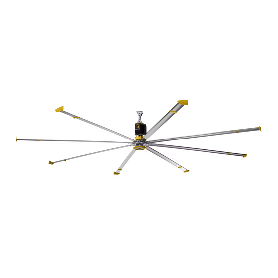
Page 11: Fan Diagram
FAN DIAGRAM Contact Customer Service if you are missing any parts or hardware needed for installation. Powerfoil Powerfoil Plus Winglet Winglet Safety Cable Variable Frequency Drive Lower Cover Beam Clips & Spacers Gearbox Airfoil Upper Mount Motor Extension Tube AirFence™ Lower Yoke Winglet WWW.BIGASSSOLUTIONS.COM... -
Page 12: Controller Diagram
CONTROLLER DIAGRAM CAUTION: The wall controller and upper temperature sensor contain sensitive electronic PCBs. Use extreme care when handling! ESD precautions recommended. Note: The illustration below does not show wiring. Mounting Plate 3.86” (9.8 cm) Wall Controller 2.8” (7 cm) Upper Temperature Sensor... -
Page 13: Where To Install Your Fan
The fans must be installed at the distance listed below according to your fan size. The distance of the fan from the ceiling should be measured from the top of the winglets to the ceiling. Powerfoil X3.0 Powerfoil X3.0 Plus Fan Diameter Distance from Ceiling... - Page 14 Clearance from HVAC equipment and radiant heaters The fan must be installed at the minimum distances shown below in relation to Heating, Ventilation, and Cooling (HVAC) systems. See the manufacturer’s requirements for the minimum clearance to combustibles. Fan located at or above HVAC discharge or intake If the fan is at the same level or above the HVAC diffuser, it must have a clearance of ≥...
- Page 15 The example below shows a situation in which the 90-Degree Offset mount must be used so that the fan hangs plumb to the ground. If you are uncertain of your roof pitch or do not have the correct mount to properly hang your fan, consult a structural engineer or contact Big Ass Fans Customer Service. Standard Upper Mount 90-Degree Offset Mount WWW.BIGASSSOLUTIONS.COM...
- Page 16 Understanding airflow patterns Correct fan placement is crucial for maximizing airflow distribution while adhering to safety standards. Airflow in an open area The airflow moves from the fan toward the floor. When airflow hits the floor, it moves outward in all directions.
- Page 17 General airflow tips Below are some techniques that make a dramatic difference in congested areas of your facility. Treat air like water, and scoop, direct, and channel it to where it is needed most. Note: Powerfoil Plus winglets deliver air from a much higher angle, resolving many of the issues outlined below.
-
Page 18: Wall Control Overview
WALL CONTROL OVERVIEW The wall control relies on air temperature readings at the locations of the wall controller and upper temperature sensor. Proper mounting locations are essential to the successful adjustment of the room temperature. Refer to the diagram and guidelines below. Upper Temperature Sensor mounting location Wall Controller mounting... -
Page 19: Installation
CAUTION: Before beginning installation, confirm that you have the appropriate mount for your roof pitch. WARNING: Ensure there are no persons below the fan during installation! Overview Big Ass Fans should only be hung from an I-beam or bar joists. Consult a structural engineer for installation methods not covered in this manual. I-Beam Angle Irons •... -
Page 20: 1A. Prepare The I-Beam
1a. Prepare I-Beam ATTENTION If you are mounting your fan to angle irons, proceed to the following page. Measure the flange width of the I-beam from which the fan will be hung. Select the mounting holes that match the flange width of the I-beam from the diagrams below. Proceed to step 2. -
Page 21: 1B. Prepare The Angle Irons
1b. Prepare Angle Irons CAUTION: Do not install the fan from a single purlin, truss, or bar joist. CAUTION: Unsupported angle iron spans should not exceed 12 ft (3.7 m). CAUTION: The angle irons must be fastened to the roof structure at each end. If you are mounting your fan to an I-beam, see the previous page. - Page 22 B. Pre-drill angle irons Before drilling the angle irons, confirm that you have the appropriate mount to accommodate your roof pitch. Drill two Ø9/16” (1.4 cm) holes exactly 5-3/8” (13.7 cm) apart in the centers of two angle irons. Measure the distance between the mounting points of the roof structure that the angle irons will span. Measure the same distance on the angle irons and drill a Ø9/16”...
- Page 23 D. Fasten angle irons to roof structure mounting points Single Angle Iron Double Angle Iron Fasten the angle irons to the roof structure mounting Fasten the angle irons to the roof structure mounting points at each end with Grade 8 hardware. Do not points at each end with Grade 8 hardware as shown.
-
Page 24: Directly Mount Main Fan Unit To Angle Irons
2. Directly Mount Main Fan Unit to Angle Irons ATTENTION If you are installing the fan with an extension tube, skip to step 3a (I-beam) or 3b (angle irons). CAUTION: The main fan unit is heavy. Use caution when raising it. A 24-ft (7.3-m) fan can weigh up to 415 lbs (188 kg). -
Page 25: 3A. Attach Upper Mount To I-Beam
3a. Attach Upper Mount to I-Beam ATTENTION If you are mounting the fan to angle irons, skip to step 3b on the following page. Secure the upper mount to the I-beam with the Upper Mount Hardware. Tighten the bolts to 40 ft·lb (54.2 N·m) using a torque wrench and 3/4”... -
Page 26: 3B. Attach Upper Mount To Angle Irons
3b. Attach Upper Mount to Angle Irons Secure the upper mount directly to the angle irons with the Upper Mount Hardware. The angle irons should be aligned with the outermost holes of the upper mount. Consult the diagrams below for distances between the angle irons. -
Page 27: Install The Extension Tube
4. Install the Extension Tube Fasten the extension tube to the upper mount with the Extension Tube Hardware. Ensure the extension tube is hanging plumb to the ground, and then tighten the hardware so that it is snug, but not fully tightened. Note: If the mounting structure requires a non-standard extension tube length, see Cutting the Extension Tube in Troubleshooting. -
Page 28: Install Lower Yoke
6. Install Lower Yoke Secure the lower yoke to the bottom of the extension tube with the Lower Yoke Hardware. Tighten the hardware so that it is snug, but not fully tightened. Lower Yoke Hardware: a. (2) 1/2-13 x 4-1/2’’ GR 8 Bolt b. -
Page 29: Confirm Orientation
8. Confirm Orientation After securing the main fan unit to the lower yoke, allow the fan to hang so that the extension tube is plumb to the ground. When it is properly positioned, fully tighten all mounting hardware to 40 ft·lb (54.2 N·m). 9. - Page 30 B. Attach beam clamps For best results, the guy wires should be installed at 45° in the X-Y, Y-Z, and X-Z planes as shown below. If the angle deviates by more than 15 degrees, contact Customer Service for assistance. Secure each beam clamp to the mounting structure at approximately 45° from the horizontal plane. Fully tighten the set screw to secure the clamp.
- Page 31 C. Route guy wire through Gripple ® Route the guy wire through the Gripple and the carabiner on the fan, and then back through the Gripple as shown. Do not tighten the Gripple until the remaining guy wires have been installed. Note: To back the guy wire out of the Gripple, insert 1/16 (1.5 mm) Allen wrench into the small hole on the Gripple.
-
Page 32: 10A. Mount The Upper Temperature Sensor
10a. Mount the Upper Temperature Sensor (to I-Beam) CAUTION: The wall controller and upper temperature sensor contain sensitive electronic PCBs. Use extreme care when handling! ESD precautions recommended. ATTENTION Do not lose the rubber grommet during installation. A. Select a mounting location Do not mount the upper sensor in the following locations: •... -
Page 33: 10B. Mount The Upper Temperature Sensor (To Wood Beam)
10b. Mount the Upper Temperature Sensor (to Wood Beam) CAUTION: The wall controller and remote temperature sensor contain sensitive electronic PCBs. Use extreme care when handling! ESD precautions recommended. ATTENTION Do not lose the rubber grommet during installation. A. Select a mounting location Do not mount the upper sensor in the following locations: •... -
Page 34: Mount The Wall Controller
11. Mount the Wall Controller CAUTION: The wall controller and upper temperature sensor contain sensitive electronic PCBs. Use extreme care when handling! ESD precautions recommended. The wall control incorporates an internal temperature sensor and should be mounted within the same zone as the upper temperature sensor. -
Page 35: 12A. Wire The Wall Control
12a. Wire the Wall Control The diagram below shows typical wall control wiring on a single Powerfoil X 3.0 or Powerfoil X 3.0 Plus fan. See ® ® the next section for alternative wiring methods. If wiring multiple fans, see “Daisy Chaining” for details and wiring diagrams. -
Page 36: 12B. Alternative Wall Control Wiring Methods
12b. Alternative Wall Control Wiring Methods If there is not a 120 VAC receptacle within six (6) feet of the desired wall controller location, the installer can extend the cord of the provided power supply as needed or use one of the alternate wiring methods shown below utilizing a 3-conductor shielded cable. -
Page 37: Mount The Auxiliary Controller
13. Mount the Auxiliary Controller WARNING: To reduce the risk of electric shock, wiring should be performed by a qualified electrician! Incorrect assembly can cause electric shock or damage the motor and the auxiliary controller! ATTENTION The auxiliary controller is required for fan operation. A. -
Page 38: Wire The Fan
14. Wire the Fan WARNING: To reduce the risk of electric shock, wiring should be performed by a qualified electrician! Incorrect assembly can cause electric shock or damage the motor and the controller! Make sure power wiring is routed to the installation site. See “Wiring Diagrams” for instructions and guidelines on wiring your fan. - Page 39 B. Position airfoils Slide the airfoils onto the tabs of the fan hub. Do not fasten the airfoils to the hub with hardware at this step. The airfoils must be attached to the fan hub with the curved sides facing downward. C.
-
Page 40: Install The Hub Cover
16. Install the Hub Cover If your fan order included accessories (light or camera), install those accessories before securing the hub cover. Secure the hub cover to the hub with the Hub Cover Hardware. Hub Cover Hardware: a. (4) 1/4” Plastic Rivet Hub Cover WWW.BIGASSSOLUTIONS.COM ©... -
Page 41: Electrical Guidelines
ELECTRICAL GUIDELINES WARNING: Installation must comply with specifications from National Electrical Codes and standards (NEC, VDE, BSI, etc.) regarding wire types, conductor sizes, branch circuit protection, and disconnecting devices. WARNING: To avoid a possible shock hazard and/or nuisance tripping caused by induced voltages, unused wires in the conduit must be grounded at both ends. -
Page 42: Grounding
Recommended wire size A minimum of 14 AWG is acceptable for motor leads. Power feeders to controllers must be governed by the fuse size included with the VFD and/or required circuit breaker. Grounding Due to high frequency content on the output side of the VFD, measures must be taken to ensure that all grounding connections conform to the recommendations made in this section. -
Page 43: Delta Secondary
Delta secondary Care must be taken when connecting to a three-phase, 240/120 V secondary as shown below. All VFD models rely on internal references made between each incoming phase and ground. To prevent nuisance tripping such as Overvoltage and Undervoltage faults, 200–240 V, three-phase VFDs should be connected so that the High Leg, or “phase B,”... -
Page 44: Branch Circuit Protection
Branch circuit protection The VFDs include fuses for branch short circuit protection and can be installed with a dedicated fusible disconnect and/or input circuit breaker. National and local industrial safety standards and/or electrical codes may determine additional requirements for these installations. Means for disconnection should be incorporated in the fixed wiring in accordance with all applicable national wiring rules. -
Page 45: Wiring: 200-240 V, 1 Φ
Wiring: 200–240 V, 1 Φ WARNING: Wait three minutes after disconnecting before servicing! WARNING: Improper installation can cause electric shock or damage to the motor and VFD! A qualified electrician should perform the installation. The diagram below shows a standard VFD (200–240 V, 1 Φ) using single-phase input from AC power supply. Actual component layout may differ from illustration. -
Page 46: Wiring: 200-240 V, 1 Φ With Line Reactor
Wiring: 200–240 V, 1 Φ with Line Reactor WARNING: Wait three minutes after disconnecting before servicing! WARNING: Improper installation can cause electric shock or damage to the motor and VFD! A qualified electrician should perform the installation. The diagram below shows a typical line reactor installation on a standard VFD (200–240 V, 1 Φ) using single-phase input from AC power supply. -
Page 47: Wiring: 200-240 V, 1 Φ With Emi Filter
Wiring: 200–240 V, 1 Φ with EMI Filter WARNING: Wait three minutes after disconnecting before servicing! WARNING: Improper installation can cause electric shock or damage to the motor and VFD! A qualified electrician should perform the installation. The diagram below shows a typical EMI filter installation on a standard VFD (200–240 V, 1 Φ) using single-phase input from AC power supply. -
Page 48: Wiring: 200-240 V, 3 Φ
Wiring: 200–240 V, 3 Φ WARNING: Wait three minutes after disconnecting before servicing! WARNING: Improper installation can cause electric shock or damage to the motor and VFD! A qualified electrician should perform the installation. The diagram below shows a standard VFD (200–240 V, 3 Φ) using three-phase input from AC power supply. Actual component layout may differ from illustration. -
Page 49: Wiring: 200-240 V, 3 Φ With Line Reactor
Wiring: 200–240 V, 3 Φ with Line Reactor WARNING: Wait three minutes after disconnecting before servicing! WARNING: Improper installation can cause electric shock or damage to the motor and VFD! A qualified electrician should perform the installation. The diagram below shows a typical line reactor installation on a standard VFD (200–240 V, 3 Φ) using three-phase input from AC power supply. -
Page 50: Wiring: 200-240 V, 3 Φ With Emi Filter
Wiring: 200–240 V, 3 Φ with EMI Filter WARNING: Wait three minutes after disconnecting before servicing! WARNING: Improper installation can cause electric shock or damage to the motor and VFD! A qualified electrician should perform the installation. The diagram below shows a typical EMI filter installation on a standard VFD (200–240 V, 3 Φ) using three-phase input from AC power supply. -
Page 51: Wiring: 400-480 V, 3 Φ
Wiring: 400–480 V, 3 Φ WARNING: Wait three minutes after disconnecting before servicing! WARNING: Improper installation can cause electric shock or damage to the motor and VFD! A qualified electrician should perform the installation. The diagram below shows a standard VFD (400–480 V, 3 Φ) using three-phase input from AC power supply. -
Page 52: Wiring: 400-480 V, 3 Φ With Line Reactor
Wiring: 400–480 V, 3 Φ with Line Reactor WARNING: Wait three minutes after disconnecting before servicing! WARNING: Improper installation can cause electric shock or damage to the motor and VFD! A qualified electrician should perform the installation. The diagram below shows a typical line reactor installation on a standard VFD (400–480 V, 3 Φ) using three-phase input from AC power supply. -
Page 53: Wiring: 400-480 V, 3 Φ With Emi Filter
Wiring: 400–480 V, 3 Φ with EMI Filter WARNING: Wait three minutes after disconnecting before servicing! WARNING: Improper installation can cause electric shock or damage to the motor and VFD! A qualified electrician should perform the installation. The diagram below shows a typical EMI filter installation on a standard VFD (400–480 V, 3 Φ) using three-phase input from AC power supply. -
Page 54: Wiring: 575-600 V, 3 Φ
Wiring: 575–600 V, 3 Φ WARNING: Wait three minutes after disconnecting before servicing! WARNING: Improper installation can cause electric shock or damage to the motor and VFD! A qualified electrician should perform the installation. The diagram below shows a standard VFD (575–600 V, 3 Φ) using three-phase input from AC power supply. Actual component layout may differ from illustration. -
Page 55: Wiring: Fire Relay (E Series)
Wiring: Fire Relay (E Series) WARNING: Wait three minutes after disconnecting before servicing! ATTENTION: If installing the fan in the United States, the fan must be installed per the following National Fire Protection Association (NFPA) guidelines: • The fan must be centered approximately between four adjacent sprinklers. •... -
Page 56: Wiring: Fire Relay (M Series)
Wiring: Fire Relay (M Series) WARNING: Wait three minutes after disconnecting before servicing! ATTENTION: If installing the fan in the United States, the fan must be installed per the following National Fire Protection Association (NFPA) guidelines: • The fan must be centered approximately between four adjacent sprinklers. •... -
Page 57: Daisy Chaining
Daisy chaining The Powerfoil X3.0 fan is preprogrammed to operate in Master/Slave or Daisy Chain mode. The wall controller for the master fan will act as the master controller, and all auxiliary controllers remain active as a display so that the operator can still view any fault messages, toggle between output frequency and fan RPM displays, or operate the fan via the LOCAL/REM button. - Page 58 Changing fan parameters CAUTION: Under no circumstances should an operator attempt to alter the programming of the VFD without the assistance of an authorized Big Ass Fans installer, the Customer Service Department, or the Engineering Department. WARNING: Before making parameter changes, ensure that the fan is stopped.
-
Page 59: Daisy Chaining (Auxiliary Controller Only)
REM mode, will follow command references provided by the master fan VFD. Refer to the following page for detailed wiring diagrams. Limit two-conductor shielded cable runs to 200 ft (61 m) or less. Consult Big Ass Fans Customer Service Department for conversion to 4–20 mA current loop. System redundancy If one of the fans in the chain is disabled, the next fan in the chain can become the master controller for all remaining fans by pressing the LOCAL/REM button on that fan’s wall controller. - Page 60 Auxiliary controller wiring for daisy chaining Reverse fan rotation is disabled when the fan is operated as a slaved unit. Note: To access all buttons on the auxiliary controller, the button cover must be removed (if used). RS-485 1:Reserved 2:EV 3:GND 4:SG- 5:SG+...
-
Page 61: Basic Distributed I/O Interface; Local Control
Basic distributed I/O interface; LOCAL control Note: RA to Digital Input #1 jumper removed. RS-485 1:Reserved 2:EV 3:GND 4:SG- 5:SG+ 6:Reserved 7:Reserved 8:Reserved FWD / STOP Digital Input STOP Digital Input REV / STOP Digital Input LOCAL MODE Digital Input Digital Input Digital Input PROG... -
Page 62: Basic Distributed I/O Interface; External Control
About I/O mode selection Big Ass Fans factory defaults for analog and digital inputs are ACI (4–20 mA) and NPN (inputs pulled down to DC Common). If required, these may be switched to AVI (0–10 VDC as shown above) and PNP (inputs pulled up to 24 VDC) via the dip switches. -
Page 63: Interfacing With Basic Timers, Thermostats, And Other Equipment
Interfacing with basic timers, thermostats, and other equipment RS-485 1:Reserved 2:EV 3:GND 4:SG- 5:SG+ 6:Reserved 7:Reserved 8:Reserved Digital Input STOP Digital Input Digital Input LOCAL MODE Digital Input Digital Input Digital Input PROG Thermostat, timer, DATA or other equipment auxiliary Digital contact STOP... -
Page 64: Starting And Stopping The Fan
WALL CONTROLLER OPERATION The Powerfoil X3.0 and Powerfoil X3.0Plus fans are pre-configured at the factory to Wall Controller accept dual control sources. The auxiliary controller keypad allows you to toggle these sources easily using the LOCAL/REM button. When the LOC indicator is illuminated on the auxiliary controller, the Start, Stop, and Speed functions are controlled solely by the auxiliary controller. -
Page 65: Programming The Wall Control
Summer Mode In Summer Mode, only the temperature at the floor level is monitored. Based on this reading, fan speed adjusts according to the user-defined temperature and speed setting. Below are two examples of how the wall controller can be programmed. In Example 1, the maximum winter fan speed is limited to 30%. - Page 66 AUTOMATIC To program the minimum and maximum speed temperatures for Summer Mode: DESTRATI DESTRATIFICATION SYSTEM 1. To select Summer Mode, repeatedly press the 85% Speed Temp Displayed Mode button on the wall controller until the red MAXIM Summer Mode LED is illuminated. After selecting MAXIMUM FAN SPEED 100% Summer Mode, press and hold the Mode button...
-
Page 67: Starting, Stopping, And Direction Control
AUXILIARY CONTROLLER OPERATION Auxiliary Upon initial power-up of the fan, the auxiliary controller appears as shown on the right. The auxiliary controller is programmed to show the fan’s current running speed Controller in RPM on the LED display. The display also indicates if the fan is stopped (STOP), set to run forward (FWD), or is set to respond to a remote control source (REM) such as an Energy Management System or Building Automation System. -
Page 68: Cycling Through The Led Display Modes
Cycling through the LED display modes To cycle through the possible display options on the auxiliary controller, press the MODE button MODE repeatedly. Below are the possible screens in the order in which they appear on the display. Note: To access the MODE button, the controller's button cover must be removed (if used). -
Page 69: Locking And Unlocking Procedures
Locking and unlocking procedures To lock or unlock the auxiliary controller, follow the chart below. Note: To access the required buttons, the controller's button cover must be removed (if used). Frequency Output Current User Selected Frequency Command “F” Display Value “U” Output “H”... -
Page 70: Understanding And Clearing Fan Faults
Understanding and clearing fan faults External faults EF or “External Fault” is displayed when the fan has stopped due to an alarm condition. EF also displays if the user has interfaced the fan system with other equipment requiring fan STOP shutdown, such as an ESFR system. -
Page 71: Preventive Maintenance
• Observe the motion of the fan during operation. The fan should not wobble or gyrate. If any wobble is noticed, ensure the mounting structure is rigid enough to support the fan and that the guy wires, if used, are sufficiently taut. If guy wires were not used, Big Ass Fans suggests installing them. Contact Customer Service if wobbling persists. -
Page 72: Annual Maintenance Checklist
ANNUAL MAINTENANCE CHECKLIST Fan Model: Fan Model: Fan Model: Serial #: Serial #: Serial #: Location: Location: Location: Date Initials Date Initials Date Initials WWW.BIGASSSOLUTIONS.COM © 2016 DELTA T CORP. ALL RIGHTS RESERVED. -
Page 73: General Troubleshooting
GENERAL TROUBLESHOOTING Some issues can be resolved before requesting service. Review the troubleshooting tips listed below before contacting Customer Service for support. Customers in the United States Customers outside of the United States For questions about your product or customer For questions about your product or customer service inquiries, please call our toll free number service inquiries, please contact your local Big Ass... -
Page 74: Wall Controller Troubleshooting
Wall Controller Troubleshooting During operation, the auxiliary controller keypad display will typically show the command frequency from the wall controller. If the display reports the error code shown below accompanied by fan shutdown or slowdown, one of the following conditions has occurred: •... -
Page 75: Cutting The Extension Tube
Cutting the extension tube CAUTION: Make sure the safety cable is not damaged after cutting and drilling the extension tube! If your mounting structure requires a non-standard extension tube length, use the guidelines below to cut the extension tube. WWW.BIGASSSOLUTIONS.COM ©... - Page 76 E Series fan error codes Review the below error codes and corrective actions before contacting Customer Service for support. Error code Description and corrective action Over Current Abnormal condition exists on the motor side of the fan system. Check motor OL point parameters. Check the motor wiring for shorts. If the condition persists with the disconnected motor, contact Customer Service.
- Page 77 E Series fan error codes (cont.) Error code Description and corrective action Internal Memory Error If the power cycle is not resolved, perform a parameter hard reset. If the condition persists, contact Customer Service. Communications Error—Slave Verify proper data wiring between the drive’s RS485 port and the command source. Base Block Base Block input (M4) has been triggered.
- Page 78 M Series fan error codes Review the below error codes and corrective actions for your auxiliary controller before contacting Customer Service for support. Error code Description and corrective action Over Current Abnormal condition exists on the motor side of the fan system. Check motor OL point parameters.
- Page 79 M Series fan error codes (cont.) Error code Description and corrective action Various Unrecoverable Errors If the power cycle will not clear these faults, contact Customer Service. Internal Memory Error If the power cycle is not resolved, perform a parameter hard reset. If the condition persists, contact Customer Service.
-
Page 81: Contact Us
CONTACT US Talk to a Big Ass Fan Expert. Call us at one of the numbers below or visit www.bigasssolutions.com Customer Service United States Canada 2348 Innovation Drive 6300 Northwest Dr, Unit 3 Lexington, KY 40511 Mississauga, ON L4V 1J7 Canada 877-244-3267 1-844-924-4277... -
Page 83: Check-In Procedure
CHECK-IN PROCEDURE (Big Ass Fans Certified Installers Only) ATTENTION These items must be completed prior to any additional installation crew members entering the job site or any installation material being unloaded. Date: Company: Job Name: Address: Purchase Order No.: City/State/ZIP:... - Page 84 National Fire Protection Association Standard for HVLS — United States and Canada In accordance with sections 12.1.4 and 11.1.7: High Volume Low Speed (HVLS) Fans of NFPA 13, the installation of HVLS fans in buildings equipped with sprinklers, including ESFR sprinklers, shall comply with the following: •...
-
Page 85: Close-Out Procedure
CLOSE-OUT PROCEDURE (Big Ass Fans Certified Installers Only) Date: Company: Job Name: Address: Purchase Order No.: City/State/ZIP: Contact Name: Phone: E-mail: **SEE THE FOLLOWING PAGE FOR NFPA REGULATIONS** The field crew supervisor and facility manager are to walk through the completed installation. - Page 86 ☐ Customer declined install of controller included Scope of Work standard as part of Powerfoil X3.0 fan kit ☐ Big Ass Fans-certified installer installed the 110 V ☐ SmartSense not included on order per salesperson receptacle Additional Comments: Signatures of both parties are required to acknowledge that this installation has been completed to customer satisfaction, activate warranty, and to issue payment to contractor (with required documentation).
- Page 88 PX3-INST-80-MUL-01 Rev. F 2425 Merchant St., Lexington, KY 40511 1 (877) BIG-FANS | WWW.BIGASSFANS.COM...
Need help?
Do you have a question about the Powerfoil X3.0 Plus and is the answer not in the manual?
Questions and answers