
Related Manuals for Armstrong 4382 ivs


Summary of Contents for Armstrong 4382 ivs
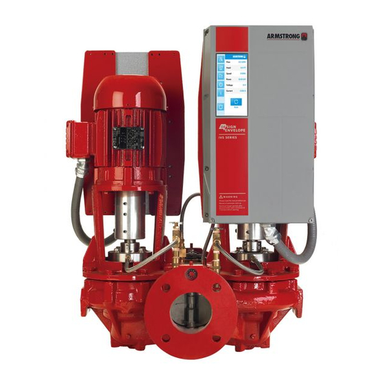
- Page 1 Installation and operating instructions Design Envelope 4302 and 4382 IVS vertical in-line pumping unit with integrated controls File No: 94.82 Date: november 23, 2012 Supersedes: 94.82 Date: january 30, 2012...
-
Page 3: Table Of Contents
Uncrating Remote lcp keypad wiring 4.8.4 Handling 4302 ivs Programming, monitoring & 4382 ivs units and diagnotics Installation glcp functions and operation Mechanical installation Indicator lights (leds) Location Control keys 2.1.1 Storage Programming 2.1.2 Installation Parameter selection 2.1.3 5.4.1 Pump piping –... -
Page 4: Uncrating
2.1.3 installation The most important consideration when installing a Series 4302 ivs and 4382 ivs pumping unit is to make sure the pump is free to ‘fl oat’ with expansion and contraction of the piping. Recommended arrangements are: •... -
Page 5: Pump Piping - General
fl ush line. Ensure the strainer are typical. entrained air is removed from series 4302 ivs and 4382 ivs Test suction line for air leaks before starting; this becomes pumps, prior to starting, through the air vent on the seal fl ush essential with long suction line or static lift. -
Page 6: General Care
Design Envelope 4302 ivs and 4382 ivs vertical i nstal latio n & in-line pumping unit with integrated controls operati ng instr uction s Start the pump with the discharge valve closed and the suc- Check the lubrication instructions supplied with the motor for... - Page 7 Design Envelope 4302 ivs and 4382 ivs vertical in sta l l a t io n & in-line pumping unit with integrated controls o per atin g in stru ct io n s Automatic fl apper operation armstrong dualarm hvac pump flapper valve oper ating instructions In the fl...
- Page 8 Design Envelope 4302 ivs and 4382 ivs vertical i nstal latio n & in-line pumping unit with integrated controls operati ng instr uction s locking arm (4) locates in the recess on the locking handle (3). warning: 4 Loosen set screw (11) and raise locking arm (3) to the vertical...
- Page 9 Design Envelope 4302 ivs and 4382 ivs vertical in sta l l a t io n & in-line pumping unit with integrated controls o per atin g in stru ct io n s fi g. 1.2 Suction valve fi g. 1.3 Discharge valve fi...
-
Page 10: Enclosure Rating
3 .1 enclosure r ating The standard enclosure rating for Series 4302 ivs and 4382 ivs integrated controls is nema/ul type 12. If the pump is to be installed in a wet or dusty environment then a higher enclosure rating may be required (contact Armstrong) 3 . -
Page 11: Electrical Installation
Design Envelope 4302 ivs and 4382 ivs vertical in sta l l a t io n & in-line pumping unit with integrated controls o per atin g in stru ct io n s 4 .0 electrical installation 4 . 2 start / stop of pump... -
Page 12: Grounding And It Mains
The inverter must be protected against short-circuit to avoid 10hp and below) electrical or fi re hazard. Armstrong recommends using the fuses detailed in the separate ivs102 Operating Instructions to pro- tect service personnel or other equipment in case of an internal failure in the unit. -
Page 13: Relay Connections
Design Envelope 4302 ivs and 4382 ivs vertical in sta l l a t io n & in-line pumping unit with integrated controls o per a tin g in str uctio n s fig . 7 Relay connection terminals for c1 and c2 units 4 .7 relay connections... -
Page 14: Electrical Installation
Design Envelope 4302 ivs and 4382 ivs vertical i nstal latio n & in-line pumping unit with integrated controls operati ng instr uction s 4 .8 electrical installation and control connections fig . 8 Diagram showing all electrical connections *Note: terminal 37 is not available on ivs sensorless pumps... -
Page 15: Access To Terminals
Design Envelope 4302 ivs and 4382 ivs vertical in sta l l a t io n & in-line pumping unit with integrated controls o per atin g in stru ct io n s Control terminal functions and factory settings are as follows: 4 .8.1 access to terminals... -
Page 16: Connection Examples
Design Envelope 4302 ivs and 4382 ivs vertical i nstal latio n & in-line pumping unit with integrated controls operati ng instr uction s 4 .8.3 connection examples ii closed loop – with sensor feedback ivs Sensorless pumps can be confi gured in four main ways: To control the pump based on a 4-20mA feedback signal from a sensor use the following connection. -
Page 17: Remote Lcp Keypad Wiring
Design Envelope 4302 ivs and 4382 ivs vertical in sta l l a t io n & in-line pumping unit with integrated controls o per atin g in stru ct io n s iii constant curve mode – potentiometer iv.i constant curve mode - bms signal... -
Page 18: Programming, Monitoring
Design Envelope 4302 ivs and 4382 ivs vertical i n sta l la t io n & in-line pumping unit with integrated controls o p er a t i n g i nstr uct ion s The number of the Active Set-up (Sensorless mode being setup 5 progr amming, monitoring 1) is shown. -
Page 19: Indicator Lights (Leds)
Design Envelope 4302 ivs and 4382 ivs vertical in sta l l a t io n & in-line pumping unit with integrated controls operat ing instruct io ns Alarm Log 5 . 2 indicator lights (leds) Displays an Alarm list of the fi ve latest alarms (numbered a1- If certain threshold values are exceeded, the alarm and/or a5). -
Page 20: Programming
Design Envelope 4302 ivs and 4382 ivs vertical i nstal latio n & in-line pumping unit with integrated controls operati ng instr uction s The following parameter groups are accessible: The low water device input must be made for the pump to start in either hand mode or auto mode. -
Page 21: Changing Data
Design Envelope 4302 ivs and 4382 ivs vertical in sta l l a t io n & in-line pumping unit with integrated controls o per atin g in stru ct io n s Readout and Programming of Indexed Parameters 5 . 4 . 2 changing data Parameters are indexed when placed in a rolling stack. -
Page 22: Settings For Quadratic
Design Envelope 4302 ivs and 4382 ivs vertical i nstal latio n & in-line pumping unit with integrated controls operati ng instr uction s To change the control curve from the factory settings, the h (head) following parameters can be adjusted: Par. -
Page 23: Constant Pressure Control
Design Envelope 4302 ivs and 4382 ivs vertical in sta l l a t io n & in-line pumping unit with integrated controls o per atin g in stru ct io n s 4 Adjust the shape of the control curve if required using Par. -
Page 24: Fault Messages
Design Envelope 4302 ivs and 4382 ivs vertical i n stal l a t io n & in-line pumping unit with integrated controls o p era t ing i nstru ctio n s In the event of an alarm, the inverter will have tripped. Alarms and supply currents to the inverter. - Page 25 Design Envelope 4302 ivs and 4382 ivs vertical in sta l l a t io n & in-line pumping unit with integrated controls o per atin g in stru ct io n s wa r n i n g /a l a r m 1 3 , Over Current: a l a r m / wa r n i n g 2 6 , Brake resistor power limit: The inverter peak current limit (approx.
- Page 26 Design Envelope 4302 ivs and 4382 ivs vertical i nstal latio n & in-line pumping unit with integrated controls operati ng instr uction s wa r n i n g /a l a r m 3 4 , Fieldbus a l a r m 5 0 , ama calibration failed: Contact your Armstrong supplier.
-
Page 27: Acoustic Noise And Vibration
Design Envelope 4302 ivs and 4382 ivs vertical in sta l l a t io n & in-line pumping unit with integrated controls o per atin g in stru ct io n s wa r n i n g /a l a r m / t r i p 6 5 ,... - Page 28 Design Envelope 4302 ivs and 4382 ivs vertical i nstal latio n & in-line pumping unit with integrated controls operati ng instr uction s table 1 Alarm/warning code list description warning al arm al arm par ameter reference / trip...
- Page 29 Design Envelope 4302 ivs and 4382 ivs vertical in sta l l a t io n & in-line pumping unit with integrated controls o per atin g in stru ct io n s description warning al arm/ trip al arm/ trip...
- Page 30 Design Envelope 4302 ivs and 4382 ivs vertical i nstal latio n & in-line pumping unit with integrated controls operati ng instr uction s table 2 ivs 102 parameter settings par. name setup 1 setup 2 setup 3 (sensorless) (external sensor) (external bms) Display line 1.1 small...
- Page 31 Design Envelope 4302 ivs and 4382 ivs vertical in sta l l a t io n & in-line pumping unit with integrated controls o per atin g in stru ct io n s par. name setup 1 setup 2 setup 3...
- Page 32 t o r o n t o 23 bertrand avenue toronto, ontario canada m1l 2p3 +1 416 755 2291 b u f f a l o 93 east avenue north tonawanda new york u.s.a. 14120 -6594 +1 716 693 8813 b i r m i n g h a m heywood wharf, mucklow hill, halesowen...
Need help?
Do you have a question about the 4382 ivs and is the answer not in the manual?
Questions and answers