Satel INT-CR Manual
Proximity card arm/disarm device
Hide thumbs
Also See for INT-CR:
- Quick installation manual (2 pages) ,
- Quick installation manual (24 pages)
Table of Contents
Advertisement
Quick Links
The INT-CR proximity card arm/disarm device enables arming /
disarming and alarm clearing in many partitions by means of
proximity cards, key fobs and other 125 kHz passive transponders
(wherever used in this manual, the word "card" means a 125 kHz
passive transponder, which can have many forms and shapes).
The device can work together with SATEL made control panels:
INTEGRA (with firmware version 1.07 or newer) and VERSA. The
manual applies to the device with firmware version 2.00.
1. Installation and connection
All electric connections may only be made with power
supply disconnected.
The device is designed for indoor installation. When selecting the
installation place, remember that the distance between two
appliances fitted with the proximity card reader should be greater
than 50 cm.
Note: If the INT-CR device is mounted on metal surface, the
reading range of proximity card will be decreased.
The device is connected directly to the control panel expander bus.
The respective device wires should be connected to the control
panel terminals, as indicated in Table 1. The distance to the
control panel must not exceed 1000 meters, when the device is
Used with the INTEGRA control panel, and 600 meters, when used
with the VERSA control panel. Wherever the distance between
control panel and device does not exceed 300 m, the device can
be power supplied directly from the control panel. Where distances
to the control panel are greater, the device should be provided with
an independent source of power supply.
Wire color
brown
white
gray
green
1.1 Setting the device address
Each device which is to be connected to the expander bus must have its own individual address.
Depending on the control panel type:
for INTEGRA: you can either set any unused address from 0 to 31 range;
for VERSA: you should set an address from 16 (10h) to 21 (15h) range.
To set the address, use the DIP-switch set on the device electronics board. A numerical value is
assigned to each DIP-switch. For OFF position, the value is always 0. The numerical values assigned
to individual DIP-switches in ON position are presented in Table 2. Using a screwdriver, set the
selected DIP-switches to ON position. Sum up the numerical values assigned to them to get the
address set in the device.
PROXIMITY CARD ARM/DISARM DEVICE
®
Function
power supply
common ground
clock
data
Table 1. Way of connecting wires to control panel terminals.
INT-CR
Control panel terminal
INTEGRA
+EX / +EX1 / +EX2
COM
CK / CK1 / CK2
DT / DT1 / DT2
int-cr_en 12/11
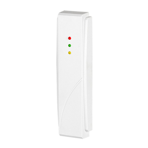
Fig. 1. INT-CR device.
VERSA
KPD
COM
CLK
DTA
Advertisement
Table of Contents

Related Manuals for Satel INT-CR


Summary of Contents for Satel INT-CR
- Page 1 50 cm. Note: If the INT-CR device is mounted on metal surface, the reading range of proximity card will be decreased. The device is connected directly to the control panel expander bus.
- Page 2 LEDs that it is waiting for the second card. This is a global option (i.e. it is available in D LOAD program for each INT-CR device, but if enabled in any device, it will be enabled in all of them). 3. Use Using the proximity card you can: ...
- Page 3 SATEL INT-CR The installer will determine the partitions to be controlled by the device. The user can only control the partitions which he is authorized to access. Note: The INTEGRA control panel does not allow to toggle between the armed mode in partitions.
- Page 4 Environmental class according to EN50130-5..................II Working temperature range....................-10...+55 °C Maximum humidity........................93±3% Housing dimensions ....................127 x 35 x 21 mm Weight .............................140 g The declaration of conformity may be consulted at www.satel.eu/ce SATEL sp. z o.o. ul. Schuberta 79 80-172 Gdańsk POLAND tel.
Need help?
Do you have a question about the INT-CR and is the answer not in the manual?
Questions and answers