
Related Manuals for Satel Abax ACU-100


Summary of Contents for Satel Abax ACU-100
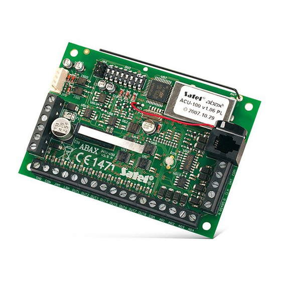
- Page 1 two-way wireless system WIRELESS SYSTEM CONTROLLER ACU-100 Program version 1.05 User Manual acu100_e 11/06...
- Page 2 Gdańsk, Poland 2005-07-15 Michał Konarski The list of countries where the ACU-100 has been approved for use - please see the website www.satel.pl The SATEL Company sets itself an objective to continually enhance quality of its products, which can entail changes to their technical specifications and software.
-
Page 3: Table Of Contents
ACU-100 SATEL CONTENTS 1. General..........................3 2. Description of ACU-100 wireless system controller ............3 2.1 Electronics board........................3 2.2 Functions of DIP-switches......................5 2.3 Control inputs ..........................5 2.4 Outputs............................7 2.5 Functional outputs ........................7 3. Wireless devices interfacing with the controller ..............8 3.1 ACX-100 Input &... - Page 4 Two-way wireless system ABAX ACU-100 6.1 LCD keypad of INTEGRA security system................32 6.2 DloadX program........................32 6.3 LCD keypad connected to controller..................34 6.3.1 Service mode of keypad connected to the controller ............... 34 6.4 Dload10 program ........................35 6.5 Description of functions, options and commands ..............
-
Page 5: General
1. G ENERAL The ACU-100 controller allows communication between any alarm control panel and the ABAX system wireless devices. It enables wire-operated security systems to be expanded by addition of wireless devices. The ABAX system is based on two-way communication. All messages sent by the devices are acknowledged, which ensures that the equipment status information will reach the controller and allows online check of the devices for their presence in the system. - Page 6 Two-way wireless system ABAX ACU-100 - information output - no radio communication with wireless device - information output - radio jamming - information output - problems with wireless device power supply OUT1…OUT8 - information output - wireless equipment status AR1…AR4 - control inputs A RS485 B - RS-485 port terminals (not used)
-
Page 7: Functions Of Dip-Switches
ACU-100 SATEL DIP- UNCTIONS OF SWITCHES DIP-switch number Controller function Wireless device module for all control panels Expander for CA-10 with 1 keypad (6 zones) Expander for CA-10 with 2 keypads (4 zones) Expander for CA-10 with 3 keypads– (2 zones) - Page 8 In order to control the ACU-100 controller inputs you can use any alarm control panel outputs (OC, high-current, low-current, relay type). Where the control is effected by means of the high-current output of a SATEL-made control panel, it is necessary to connect a 1.1kΩ resistor to the controller input (see Fig. 2).
-
Page 9: Outputs
ACU-100 SATEL In order to control the operation of sirens, you should connect the control panel alarm signaling output to the controller input. Activating the control panel output will trigger the siren. You can increase the number of inputs by adding the ACX-100 expansion modules to the controller. -
Page 10: Wireless Devices Interfacing With The Controller
Two-way wireless system ABAX ACU-100 The functional outputs may be connected to suitably programmed zones of the control panel (zone type, way of reaction, etc.). Thus the control panel will inform of any problem indicated by the controller functional output. Having obtained information on the occurrence of a problem, it can be thoroughly diagnosed by means of an LCD keypad or a computer connected to the controller. -
Page 11: Amd-101 Wireless Magnetic Detector With Additional Independent Input
ACU-100 SATEL AMD-101 W IRELESS MAGNETIC DETECTOR WITH ADDITIONAL INDEPENDENT INPUT • two reed switches • individually identifiable input to connect any outdoor detector of NC type • remote configuration of parameters • tamper contact • power supply: lithium battery, CR123A 3V... -
Page 12: Installation
Two-way wireless system ABAX ACU-100 • simulating radio communication of devices to be supplied from battery or external sources • LED indicator showing the radio signal level • buzzer • power supply: alkaline battery 9V 6LR61 4. I NSTALLATION The ABAX two-way wireless system should be installed so as to ensure a suitable level of radio signal from devices working together with the controller. -
Page 13: Connecting Computer To The Controller
ACU-100 SATEL If properly connected, the keypad will display a message, the upper line of which will include the device name and program version info. If the TROUBLE LED goes on in the keypad, one of the functional outputs is active. In order to start the service mode, the service code must be entered. -
Page 14: Connecting The Acx-100 Input & Output Expansion Modules
Two-way wireless system ABAX ACU-100 • Prior to connecting the cable, remove preliminarily the electrostatic charge, e.g. by touching a grounded piece of equipment (faucet, heater, etc.) with top of your palm. • It is recommended that the cable be first connected to the controller port. DB-25 TO CONTROLLER TO COMPUTER... -
Page 15: Adding New Wireless Devices
ACU-100 SATEL Consecutive module number Module address Control input numbers Output numbers 9-16 9-12 17-24 13-16 25-32 17-20 33-40 21-24 41-48 Table 4. Wireless system controller ACU-100 First expansion module Second expansion module ACX-100 ACX-100 address 0 address 1 module power supply Fig. -
Page 16: Lcd Keypad Connected To The Controller
Two-way wireless system ABAX ACU-100 − turn on the ARF-100 tester – immediately after start-up, the tester will send a single signal to enable registration, − plug the ASW-100 E / ASW-100 F wireless controller into the 230V socket – immediately after being plugged into the socket, the controller will send a single signal to enable registration, −... -
Page 17: Removal Of Wireless Devices
ACU-100 SATEL 3. After the „Open device tamper” is displayed: − turn on power supply of the ACX-200 expander – immediately after start-up (power-up), the expander will send a single signal to enable registration, − turn on the ARF-100 tester – immediately after start-up, the tester will send a single signal to enable registration, −... -
Page 18: Hardwired Zone / Output Expander In Abax System
Two-way wireless system ABAX ACU-100 ABAX ARDWIRED ZONE OUTPUT EXPANDER IN SYSTEM The ACX-200 expander takes up 4 positions on the list of devices supported by the controller. Up to 12 ACX-200 expanders can work together with the ACU-100 controller. The expander sends to the controller information on the status of zones and receives commands to change the status of relay outputs. -
Page 19: Configuration Of Acx-200 Expander Zones/Outputs For Acu-100 Controller Operation With Ca-64 Control Panel
ACU-100 SATEL 4.7.2 Configuration of ACX-200 expander zones/outputs for ACU-100 controller operation with CA-64 control panel The ACX-200 expander occupies 4 zones in the alarm system. Parameters of the ACX-200 zones are to be programmed in the same way as those of the other hardwired zones of the control panel. -
Page 20: Wireless Detectors In Abax System
Two-way wireless system ABAX ACU-100 ABAX IRELESS DETECTORS IN SYSTEM The wireless detectors send information on violations, tampers, and battery status to the ACU-100 controller. The detectors may be in either passive state (the system is disarmed) or in active state (the system is armed). When in the passive state (battery-saving mode), the detectors mainly communicate with the controller in time intervals determined by the option. -
Page 21: Installation Of Amd-100, Amd-101 Detectors
ACU-100 SATEL 6. Enter the test mode and set the required detector range. If necessary, modify the position of electronics board (pyroelement) in the housing, or the position of installed detector. Sensitivity of the APD-100 detectors is set by using the C functions. -
Page 22: Installation Of Asp-205 Sirens
Two-way wireless system ABAX ACU-100 The ASP-105 outdoor siren occupies two positions on the list of devices supported by the controller (separately acoustic and optical signaling). In the security system, the ASP-105 outdoor siren uses two zones through which it transmits information on the power supply status (battery and external power supply). - Page 23 ACU-100 SATEL the 7-digit serial number which is to be entered when registering the expander in the system. 2. Select the place where the ASP-205 siren is to be installed and attach it there temporarily. 3. Check the level of signal received by the controller from the siren. Select another place of installation, if necessary.
-
Page 24: Asw-100 230V Ac Wireless Controllers In Abax System
Two-way wireless system ABAX ACU-100 1st digit 2nd digit 3rd digit digit signaling duration digit acoustic signaling digit optical signaling 1 minute none disabled 3 minutes sound type 1 enabled 6 minutes sound type 2 9 minutes sound type 3 Table 8. -
Page 25: Radio Signal Level Tester In Abax System
ACU-100 SATEL The ASW-100 E and ASW-100 F controllers can work in three modes (given in square brackets is mode description in the LCD keypad of INTEGRA system): − mode 0 [button: inactive] – the electric circuit is only remotely controlled;... -
Page 26: Interaction With Alarm Control Panels
Two-way wireless system ABAX ACU-100 control panels, it is recommended that the ARF-100 tester be added as the last wireless device (after the other devices to be installed in the ABAX system). This will prevent creating an unnecessary gap due to unused zone after the tester is removed from the system. - Page 27 ACU-100 SATEL ACU-100 controller terminals +12V INTEGRA 24 / INTEGRA 32 Panel terminals +EX1 INTEGRA 64 / INTEGRA 128 +EX2 Table 9. Alarm control panel INTEGRA 64 INTEGRA 128 Wireless system controller ACU-100 Fig. 8. Example of connecting the ACU-100 controller to the INTEGRA 64 / INTEGRA 128 control panel.
- Page 28 Two-way wireless system ABAX ACU-100 gaps is difficult or even impossible when, due to the size of the premises, a number of ACU-100 controllers are operating in the system. INTEGRA 64 / 128 ACU-100 zones wyjścia List of devices Device Device detector APD-100 APD-100 detector...
-
Page 29: Addressable Zone Expander For Ca-64 Control Panel
ACU-100 SATEL Changing the wireless detectors from passive to active state takes place simultaneously with arming the partition to which the zone with wireless detector belongs. After disarming, the detectors will re-enter the passive state. It does not refer to the 24hr zones. The wireless detectors assigned to those zones remain always in the active state. -
Page 30: Zone Expander For Ca-10 Control Panel
Two-way wireless system ABAX ACU-100 devices. Control of the detectors (changeover to active / passive state), sirens (triggering alarm signal), 230V AC controller (closing / opening the electric circuit) etc. is performed through the control inputs of the ACU-100 controller. Suitably programmed outputs of the alarm control panel should be connected to the control inputs. - Page 31 ACU-100 SATEL zones and, additionally, the controller makes zones available by means of the communication bus - see Table 12). Numbers of additional system zones (zones 9 and 10 are reserved in the system for the 1 keypad zones) output 11...
-
Page 32: Wireless Device Module Interfacing With Any Alarm Control Panel
Suitably programmed outputs of the alarm control panel should be connected to the control inputs. Shown in the example, Fig. 14, is the CA-6 alarm control panel of SATEL make, however it can be any other panel as well. The controller outputs OUT1 to OUT5 are connected, respectively, to the control panel zones Z1 to Z5 (preprogrammed as type NO). -
Page 33: Programming And Diagnostics
ACU-100 SATEL Alarm control panel CA-6 Wireless system controller ACU-100 Fig. 14. Example of connecting the ACU-100 controller to the CA-6 control panel. 6. P ROGRAMMING AND DIAGNOSTICS The way of programming and the access to diagnostic functions depend on the working configuration of the controller: •... -
Page 34: Lcd Keypad Of Integra Security System
Two-way wireless system ABAX ACU-100 − computer with D 10 program connected to controller RS-232 port for the time of LOAD programming. INTEGRA KEYPAD OF SECURITY SYSTEM In order to configure the controller using the LCD keypad follow the instructions below: 1. - Page 35 ACU-100 SATEL Fig. 15. Configuration of the ACU-100 controller in D X program. Given under information LOAD on the module type and address is the version of its firmware. The wireless devices have been registered in the controller as recommended earlier in this manual: the devices which occupy both zones and outputs in the system were added first, while the devices taking up zones only were added after them.
-
Page 36: Lcd Keypad Connected To Controller
Two-way wireless system ABAX ACU-100 Fig. 16. D X program window showing signal level and quality of controller LOAD communication with wireless devices. Troubles of wireless devices (no communication, low battery level, jamming) can be read out in the D X program in the T window. -
Page 37: Dload10 Program
ACU-100 SATEL The menu of service mode in LCD keypad connected to the controller: Service end New device Remove device Device names Serial number Inputs Outputs Settings Response period Filter Configuration Trouble indication Input types Output type Set defaults Tests... - Page 38 Two-way wireless system ABAX ACU-100 Fig. 17. Activation of the ACU-100 controller support in the D 10 program. LOAD 6. Having established communication, the program will compare identifiers in computer and controller, and if they coincide, it will read data from the controller. 7.
- Page 39 ACU-100 SATEL Fig. 18. ACU-100 controller operating window in the D 10 program. LOAD Fig. 19. D 10 program window with a diagram of the level of radio signal received by the LOAD controller.
-
Page 40: Description Of Functions, Options And Commands
Two-way wireless system ABAX ACU-100 ESCRIPTION OF FUNCTIONS OPTIONS AND COMMANDS Identifier – the identifier in the D 10 program is intended to protect the controller against LOAD an attempt of unauthorized reprogramming. The identifier consists of 16 characters. By default, these are 0 only. - Page 41 ACU-100 SATEL Filter – it is possible to define the number of unanswered polls, after which "no communication" will be reported. You may enter the values from the range of 0 to 50. Entering the digit 0 will disable control of the device for presence in the system.
-
Page 42: Restoring Controller Default Settings
Two-way wireless system ABAX ACU-100 possible jamming is given in the user menu, T submenu, and in the D ROUBLES LOAD program, in the "Troubles" window . Test mode – activation of the test mode makes all the wireless devices indicate communication with the controller by blinking LEDs. -
Page 43: Technical Data
ACU-100 SATEL • D 10 identifier: 0000000000000000; LOAD • response period: 24s; • problem signaling: LED indicator; • no registered wireless devices. The default (factory) settings can be restored by means of the S function in the ET DEFAULT keypad connected to the controller, or by way of hardware restart. In order to restore the defaults by means of the hardware restart, follow the instructions below: 1. -
Page 44: History Of The Manual Updates
INTEGRA series control panels, by means of D 10 program (p. 31 and 36). LOAD • Supplemented information on „Test mode” (p. 40). SATEL sp. z o.o. ul. Schuberta 79 80-172 Gdańsk POLAND tel. + 48 58 320 94 00 info@satel.pl...
Need help?
Do you have a question about the Abax ACU-100 and is the answer not in the manual?
Questions and answers