Graf one2clean plus Installation Instructions Manual
Hide thumbs
Also See for one2clean plus:
- Instruction for operation and maintenance (40 pages) ,
- Installation instructions manual (40 pages)
Table of Contents
Advertisement
Quick Links
one2clean / one2clean plus installation
one2clean
Item no.
106850 Set-up kit 3 inhabitants
106851 Set-up kit 5 inhabitants
106852 Set-up kit 7 inhabitants
106853 Set-up kit 9 inhabitants
one2clean plus
Item no.
106417 / 106413 Set-up kit 3 inhabitants
106418 / 106414 Set-up kit 5 inhabitants
106419 / 106415 Set-up kit 7 inhabitants
106420 / 106416 Set-up kit 9 inhabitants
It is essential that you observe the
points described in these instruc-
tions. Failure to do so will invali-
date all warranty claims. For all
additional items ordered from
GRAF, separate installation in-
structions will be provided in the
transport packaging.
It is essential that you check the
components for possible damage
before installation.
You will receive separate instruc-
tions for assembling the system.
mail@graf.info
www.graf.info
instructions
Contents
1.
2.
2.1
2.2
3.
4.
5.
6.
7.
13
14
14
14
15
16
20
21
22
Advertisement
Table of Contents

Related Manuals for Graf one2clean plus


Summary of Contents for Graf one2clean plus
-
Page 1: Table Of Contents
/ one2clean plus installation instructions one2clean Item no. 106850 Set-up kit 3 inhabitants 106851 Set-up kit 5 inhabitants 106852 Set-up kit 7 inhabitants 106853 Set-up kit 9 inhabitants one2clean plus Item no. 106417 / 106413 Set-up kit 3 inhabitants... -
Page 2: Scope Of Delivery
934017 PVC hose, 20 meters, blue, 19 x 3 mm 934020 Core drill with a diameter of 124 mm. This can be purchased from Otto Graf GmbH using item • number 202003. The Carat S septic tank and covers are to be ordered separately. -
Page 3: Notes
Only genuine GRAF covers or covers that GRAF has approved in writing must be used. GRAF offers an extensive range of accessories, which are all coordinated to one another and can be expanded to form complete systems. The use of accessories that have not been approved by GRAF re- sults in the exclusion of the warranty/guarantee. -
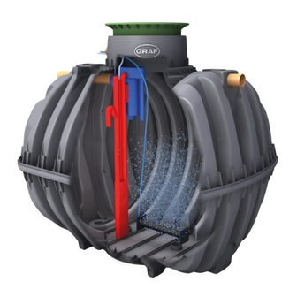
Page 4: Construction And Functional Principle
3. Construction and functional principle 3. Construction and functional principle The small wastewater treatment system is fully biological and works according to the retention process with long-term aeration. The system is made up of an aerobic stage. A scum board is used to split this stage into a coarse substance chamber and an activation chamber. -
Page 5: Assembling The Set-Up Kit
4. Assembling the set-up kit 4. Assembling the set-up kit Unfold the scum board. Place the clamps on ei- Insert the scum board into the upper shell. A ther side of the folding edges. groove offsets in an off-centre position. >... - Page 6 4. Assembling the set-up kit Place the upper shell with the scum wall on top of Assemble the clamps for connecting the upper and the lower shell. Assemble the clamps for con- lower shells. necting the upper and lower shells. 2700 L 3750 L 4800 L...
- Page 7 4. Assembling the set-up kit 2700 4800 6500 Depending on the tank size, the length of the jack Assemble the jack and sampler. To do this, push must be adjusted by moving the jack base. The the jack outflow into the sampler hole. rough position is specified on the jack.
- Page 8 4. Assembling the set-up kit 6 mm hole The cord must be secured to the pipe aerator (6 Position the pipe aerator(s) on the bottom of the mm hole). The air hose (19 mm) must be con- tank. It must be slid under the scum board such that nected on the opposite side.
-
Page 9: Assembling Control Unit In The Interior
90 Deg hose piece and hose clamps provided. Plug the compressor plug into the control sock- For further information please refer to the Con- trol Unit operating manual. Note for one2clean plus control: Assembly of one2clean plus control similar to one2clean control. 20 / 33... -
Page 10: Assembling Control Unit In The External Cabinet
6. Assembling control unit in the external cabinet 6. Assembling control unit in the external cabinet Please refer to the installation instructions for Before installing the control unit, a strip of foam rubber the External Cabinet for electrical connection must be glued to the back of the control unit. details. -
Page 11: Technical Data
1855 mm Outflow A1 470 / 800* mm 470 / 800* mm 470 / 800* mm 470 / 800* mm Outflow A2 1255 mm 1445 mm 1590 mm 1850 mm * with Maxi tank dome 22 / 33 www.graf.info 06-2018...
Need help?
Do you have a question about the one2clean plus and is the answer not in the manual?
Questions and answers