Graf one2clean User Manual
Hide thumbs
Also See for one2clean:
- Installation instructions manual (80 pages) ,
- Instruction for use & installation instructions (48 pages) ,
- Manual (28 pages)
Advertisement
Table of Contents
- 1 Table of Contents
- 2 General Notes
- 3 Function of the Wastewater Treatment System
- 4 Start-Up of the Control System
- 5 Operation of the Control System
- 6 Inspection and Maintenance
- 7 Fault Messages and Troubleshooting
- 8 Operating Notes
- 9 EC Declaration of Conformity
- 10 Declaration of Performance
- 11 Technical Data of the Control System
- Download this manual
It is essential that you observe the
points described in these instruc-
tions. Failure to do so will invali-
date all warranty claims. For all
additional items ordered from
GRAF, separate installation in-
structions will be provided in the
transport packaging.
It is essential that you check the
components for possible damage
before installation.
You will receive separate instruc-
tions for assembling the system.
Log Book
one2clean
Contents
1.
2.
3.
4.
5.
6.
7.
8.
9.
2
3
4
5
11
13
15
17
18
19
Advertisement
Table of Contents

Related Manuals for Graf one2clean


Summary of Contents for Graf one2clean
-
Page 1: Table Of Contents
For all Function of the Wastewater Treatment System additional items ordered from Start-up of the Control System GRAF, separate installation in- structions will be provided in the Operation of the Control System transport packaging. Inspection and Maintenance... -
Page 2: General Notes
• There must be a permanent power supply to the one2clean. Ensure that the control cabinet is ade- quately fused (16 A) and the power supply is fitted with isolator switch for repair & maintenance. Ad- ditional electrical components & consumers should not be using the same fuse as they can could power failure and interfere with one2clean operation. -
Page 3: Function Of The Wastewater Treatment System
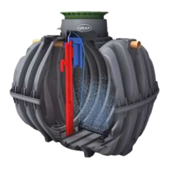
2. Function of the Wastewater Treatment System 2. Function of the Wastewater Treatment System The one2clean small wastewater treatment system is fully biological and works according to the retention process with long-term aeration (sequencing batch reactor). The system is essentially made up of an aer- obic stage. -
Page 4: Start-Up Of The Control System
3. Start-up of the Control System 3. Start-up of the Control System After the system is connected to the power supply, a short system test is run, during which time the LED light is red. The LED then becomes green when the start-up phase is completed. During the system test, the notification “SYSTEM TEST ... -
Page 5: Operation Of The Control System
4. Operation of the Control System 4. Operation of the Control System The operation of the system is carried out via a microprocessor in the control unit. The microprocessor allows for the set-up of operating parameters, the display of operating conditions and the query of system parameters as well as the programming of working times through a specialist company. - Page 6 4. Operation of the Control System 4.1.1 Display of Operating Status The operating status is indicated by the LEDs (green = operational / = fault) and as text on the screen. In normal operating mode (aeration mode), the display appears as follows: Aeration Rest: 120:10min In automatic mode, the liquid crystal display shows the current work phase and the remaining time left in...
- Page 7 4. Operation of the Control System Operating the Control System You can start different queries from the automatic mode. You can access the first operating level by pressing . You can now call up the individual queries using the arrow keys and then pressing Display Meaning...
- Page 8 4. Operation of the Control System Manual Control of the Valve using “Manual Operation” 4.2.2 During checks, each valve should run for at least 5 seconds, as the monitoring the current consumption of the valves takes some time before any faults are detected. In automatic mode, first press then the arrow key until the following is displayed on the screen:...
- Page 9 4. Operation of the Control System 4.2.4 Setting-up Holiday Mode NOTE: Holiday mode results in the reduced operation of the wastewater treatment system. It should only be applied when no wastewater is introduced into the wastewater treatment system during the selected time period.
- Page 10 4. Operation of the Control System 4.2.5 Old Faults The control system stores all past fault messages and the operation of the control system via the “manual mode” function. Past fault messages with date and time can be read under the menu item “Old faults”. The individual messages can be accessed using the arrow keys.
-
Page 11: Inspection And Maintenance
5. Inspection and Maintenance 5. Inspection and Maintenance Obligations of the Operator The system must always be turned on. The operator is obliged to ensure the fault-free operation of the system. Almost all operational faults lead to a deterioration of the system’s cleaning performance. These should therefore be detected at an early stage and eliminated immediately by you or a qualified service technician. - Page 12 5. Inspection and Maintenance Determination of Sludge Removal In order to determine the need for sludge removal in the wastewater treatment system, a settling test should be carried out at maintenance intervals. For this settling test, the SV30 is measured. The SV30 is the sludge volume occupied by 1000 ml of activated sludge after a settling period of 30 minutes.
-
Page 13: Fault Messages And Troubleshooting
6. Fault Messages and Troubleshooting 6. Fault Messages and Troubleshooting Technical problems of system operation (failure of a unit) are visually displayed. System Behaviour after switching off the Power Supply If the system is disconnected from the mains (e.g. power failure), the control program and the counted operating hours are retained due to the memory of the control system. - Page 14 6. Fault Messages and Troubleshooting Unusual Water Levels - Fixing a Fault Observation Possible cause Remedy The water level in the System is running in holiday mode End holiday mode activation tank is System runs continually in cycle ...
-
Page 15: Operating Notes
7. Operating Notes 7. Operating Notes Essentially, the system should only be supplied with materials that correspond to domestic wastewater in their characteristics. Biocides, materials with a toxic effect or materials that are not biologically compatible or degradable must not enter the system, as these lead to biological process problems. The following, in particular, should not be introduced into the system: ... - Page 16 7. Operating Notes The following is a list of individual substances which must not be disposed of via the wastewater treat- ment system: Solid or liquid substances What it does: Where it should go: that do not belong in the sink or in the toilet: Does not decompose Dustbin...
-
Page 17: Ec Declaration Of Conformity
8. EC Declaration of Conformity Manufacturer: Otto Graf GmbH Carl-Zeiss-Straße 2-6 D-79331 Teningen hereby declares that the product one2clean small sewage treatment system complies with the following Directives: 2006/42/EC Directive of the European Parliament and of the Council, dated 17 May 2006, on machinery, and amending Directive 95/16/EC. -
Page 18: Declaration Of Performance
9. Declaration of Performance 9. Declaration of Performance 18 / 19... -
Page 19: Technical Data Of The Control System
GRAF SARL – 45, Route d´Ernolsheim – F-67120 Dachstein Gare – Tel.: 0033/388497310 – Fax: 0033/388493280 GRAF Iberica – C/Marquès Caldes de Montbui, 114 baixos – ES-17003 Girona – Tel.: +34/972 913 767 – Fax: +34/972 913 766 GRAF UK Ltd – Thorpe Way Industrial Estate, Banbury – Oxfordshire OX16 4TA – Phone: +44 (0) 16 22 68 65 50...
Need help?
Do you have a question about the one2clean and is the answer not in the manual?
Questions and answers