Keysight Technologies 34921A User Manual
Low frequency multiplexer modules
Hide thumbs
Also See for 34921A:
- User manual (19 pages) ,
- User manual (62 pages) ,
- User manual (62 pages)
Table of Contents
Advertisement
Advertisement
Table of Contents

Related Manuals for Keysight Technologies 34921A


Summary of Contents for Keysight Technologies 34921A
- Page 1 Keysight 34921A-34925A Low Frequency Multiplexer Modules User’s Guide...
- Page 2 EXPRESS OR IMPLIED, WITH REGARD agreement and written consent from customarily provided to the public. TO THIS MANUAL AND ANY Keysight Technologies as governed by Accordingly, Keysight provides the INFORMATION CONTAINED HEREIN, United States and international Software to U.S. government INCLUDING BUT NOT LIMITED TO THE copyright laws.
-
Page 3: Safety Symbols
Caution, risk of electric shock Caution, risk of danger (refer to this Frame or chassis (ground) terminal manual for specific Warning or Caution information) Standby supply. Unit is not completely disconnected from ac mains when switch is off Keysight 34921A-34925A User’s Guide... -
Page 4: Additional Safety Notices
(grounding) conductor or disconnection of the protective earth terminal will cause a potential shock hazard that could result in personal injury. Do Not Operate in an Explosive Atmosphere Do not operate the instrument in the presence of flammable gases or fumes. Keysight 34921A-34925A User’s Guide... -
Page 5: Do Not Remove The Instrument Cover
In Case of Damage Instruments that appear damaged or defective should be made inoperative and secured against unintended operation until they can be repaired by qualified service personnel. Keysight 34921A-34925A User’s Guide... -
Page 6: Waste Electrical And Electronic Equipment (Weee) Directive 2002/96/ Ec
To contact Keysight for sales and technical support, refer to the support links on the following Keysight websites: – www.keysight.com/find/34980a (product-specific information and support, software and documentation updates) – www.keysight.com/find/assist (worldwide contact information for repair and service) Keysight 34921A-34925A User’s Guide... -
Page 7: Table Of Contents
....... . .11 SCPI Programming Examples for the Multiplexer Modules ..13 34921A 40-Channel Armature Multiplexer with Low Thermal Offset . .17 34921A Simplified Schematic . - Page 8 ....60 34925T-002 Terminal Block for One-Wire Mode ....62 Keysight 34921A-34925A User’s Guide...
-
Page 9: Low Frequency Multiplexer Modules
– You can connect a MUX to an external instrument, and/or switch multiple analog signals to the internal DMM. – With the 34921A, 34922A, 34923A, and the 34924A modules, you can close more than one channel in each bank simultaneously (N:1 configuration). -
Page 10: Measurement Functions For The Multiplexer Modules
[d] Impact of higher offset voltage specification (< 50 μV) must be taken into consideration. [e] 1 kΩ or higher range used unless 100Ω series resistors are bypassed on module. 10 kΩ or higher range used for loads over approximately 300Ω due to series resistance of FET channels. Keysight 34921A-34925A User’s Guide... -
Page 11: Operating Considerations
The Safety Interlock feature is implemented in hardware on the modules and CAUTION cannot be circumvented. Regardless of whether the simulation mode is enabled or disabled, all Analog Bus connections are prohibited as long as no terminal block or properly-wired cable is connected to the module. Keysight 34921A-34925A User’s Guide... - Page 12 Analog Bus relays will be closed. – The simulation setting is stored in volatile memory and will be lost when power is turned off. To re-enable the simulation mode after power has been off, you must send the command again. Keysight 34921A-34925A User’s Guide...
-
Page 13: Scpi Programming Examples For The Multiplexer Modules
“break-before-make” series. ROUTe:CLOSe (@3001:3040) The following command opens the closed channel on Bank 1 of a FET MUX module in slot 3, and closes channel 15 on that bank. ROUTe:CLOSe (@3015) Keysight 34921A-34925A User’s Guide... - Page 14 3 and 8 (of a module in slot 1) into the scan list (and redefines the scan list). The INITiate command scans the specified channels, and then sends the readings to memory. The FETCh? command transfers the readings from memory to the user. Keysight 34921A-34925A User’s Guide...
- Page 15 Example: Making current measurements The following command configures channel 43 for a 34921A modules in slot 7 for dc current measurements, triggers the internal DMM to scan the channel, and then sends the reading to the output buffer of the 34980A. The default settings for range (autorange) and resolution (1 PLC) are used for the measurement.
- Page 16 7 and 16 for a MUX module in slot 1. DIAGnostic:RELay:CYCLes:CLEar (@1007,1016) Example: Resetting mod ule(s) to power-on state The following command resets a module in slot 4 to its power-on state. SYSTem:CPON 4 Keysight 34921A-34925A User’s Guide...
-
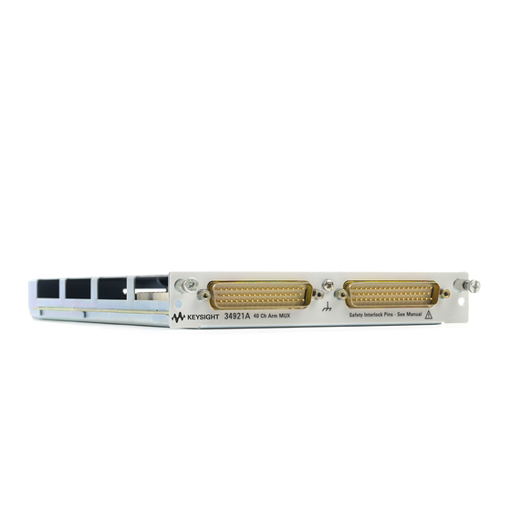
Page 17: 34921A 40-Channel Armature Multiplexer With Low Thermal Offset
(L) signal path. You cannot measure current and voltage on ABus1 simultaneously. Using program commands or the mainframe front panel, you can control each of the channel switches individually, and thus configure the 34921A module in these modes: – two independent 20-channel 2-wire MUXes. This configuration requires neither using external wiring nor connecting through the internal Analog Buses. - Page 18 ABus3. Or, externally you can connect COM1 to COM2 to create this configuration. Low thermal offset voltage makes the 34921A ideal for low-level signal switching. The 34921T optional terminal block provides a built-in thermocouple reference junction that helps minimize errors due to thermal offset when you measure thermocouples.
-
Page 19: 34921A Simplified Schematic
NOTE: The three-digit number assigned to each switch represents the channel number. NOTE: Bank Relays: Armature latching Bank 1 Analog Bus Relays: Armature non-latching COM 1 Analog Buses ABus1 ABus2 Current ABus3 ABus4 (MEAS) Current (SENS) Fuse Fuse Fuse Fuse COM 2 Bank 2 Keysight 34921A-34925A User’s Guide... -
Page 20: 34921A D-Sub Connectors
Bank 1 Analog Bus relays to close. The optional 34921T terminal block shorts these pins for you. This feature protects inadvertent routing of high voltages from the Analog Bus to the D-sub connector of the module. Keysight 34921A-34925A User’s Guide... - Page 21 Bank 2 Analog Bus relays to close. The optional 34921T terminal block shorts these pins for you. This feature protects inad vertent routing of high voltages from the Analog Bus to the D-sub connector of the module. Keysight 34921A-34925A User’s Guide...
-
Page 22: 34921T Terminal Block
PC board as shown below. Also shown are two holes that you can use for connecting an external temperature reference to the terminal block. Temperature Sensor External Reference 34921T (viewed from bottom side) Keysight 34921A-34925A User’s Guide... - Page 23 The cables provide communication and power to the temperature sensor on the 34921T terminal block. If cabling is not correct, an error may occur indicating that the 34921A module is not fully operational. Keysight 34921A-34925A User’s Guide...
-
Page 24: 34922A 70-Channel Armature Multiplexer
Analog Bus. For more information, see “Safety Interlock” page 11 and “34922A D-Sub Connectors” on page 26. When the power is off, all channel relays maintain state, and the Analog Bus relays open. Keysight 34921A-34925A User’s Guide... -
Page 25: 34922A Simplified Schematic
NOTE: The three-digit number assigned to each switch represents the channel number. NOTE: Bank Relays: Armature latching Bank 1 Analog Bus Relays: Armature non-latching COM 1 Analog Buses ABus1 ABus2 ABus3 ABus4 (MEAS) (SENS) COM 2 Bank 2 Keysight 34921A-34925A User’s Guide... -
Page 26: 34922A D-Sub Connectors
Bank 1 78-Pin D-Sub Male Connector Interlock1 15L Interlock 1 Description Description Description Description Description Description COM1 H COM1 L Interlock 1 Interlock 1 No Connect 77 No Connect 78 Keysight 34921A-34925A User’s Guide... - Page 27 78-Pin D-Sub Male Connector 55L Interlock 2 GND 61H 50L Interlock 2 GND 67H Description Description Description Description Description Description COM2 H COM2 L Interlock 2 Interlock 2 No Connect 77 No Connect 78 Keysight 34921A-34925A User’s Guide...
-
Page 28: 34922T Terminal Blocks
(no terminal block or cable is connected), the Analog Bus relays are open and disconnected from the Analog Buses. See “Safety Interlock” on page 11 for further information. Keysight 34921A-34925A User’s Guide... - Page 29 34922T-001 Terminal Block This terminal block with solder-type connections is labeled with the model number and the abbreviated module name. In addition, space is available on the label for you to write the slot number. Keysight 34921A-34925A User’s Guide...
- Page 30 34922T-002 Terminal Block This terminal block with screw-type connections is labeled with the model number and the abbreviated module name. In addition, space is available on the label for you to write the slot number. COM2 36 COM1 Keysight 34921A-34925A User’s Guide...
-
Page 31: 34923A 40/80-Channel Reed Multiplexer
This module is interlock protected, which means whenever the D-sub connector end of the modules is exposed, the Analog Bus relays immediately open and disconnect from the Analog Bus. For more information, see “Safety Interlock” page 11 and the D-Sub connector drawings on page 35 page Keysight 34921A-34925A User’s Guide... -
Page 32: Two-Wire Mode
Bank 1 (source) with channel n+20 on Bank 2 (sense) to provide these connections. Four-wire controls occur only when doing 4-wire measurement operations through the internal DMM, such as MEASure:FRESistance? or scanning a channel previously configured as 4-wire. Keysight 34921A-34925A User’s Guide... -
Page 33: One-Wire Mode
These channels are split 20 to a bank. For example, with one Analog Bus relay closed you can close up to a maximum of 39 channel relays. If you try to close more than the allowed number of channels, you will receive an error message. Keysight 34921A-34925A User’s Guide... -
Page 34: 34923A Simplified Schematic For Two- Or Four-Wire Mode
NOTE: Bank Relays: Reed non-latching Analog Bus Relays: Armature non-latching COM 1 100Ω 100Ω 100Ω 100Ω 100Ω 100Ω Analog Buses ABus1 ABus2 ABus3 ABus4 (MEAS) (SENS) 100Ω 100Ω 100Ω 100Ω 100Ω 100Ω COM 2 Bank 2 Keysight 34921A-34925A User’s Guide... -
Page 35: 34923A D-Sub Connectors For Two- Or Four-Wire Mode
20H 20L Interlock1 50-Pin D-Sub Male Connector Reserved 11H 19H 19L 15H 15L Interlock 1 Reserved 16L 12H Description Description Description Description Description COM1 H COM1 L Interlock 1 Interlock 1 Reserved Reserved Reserved Reserved Reserved Keysight 34921A-34925A User’s Guide... - Page 36 Bank 2 Analog Bus relays to close. The optional 34923T-001 (for 2-wire) shorts these pins for you. This feature protects inadvertent routing of high voltages from the Analog Buses to the D-sub connector of the module. Keysight 34921A-34925A User’s Guide...
-
Page 37: 34923T-001 Terminal Block For Two-Wire Or Four-Wire Mode
34923T-001 terminal block that corresponds to the 2- or 4-wire configuration mode. An error will not be generated if you have installed a terminal block that doesn't match the present module configuration. Keysight 34921A-34925A User’s Guide... -
Page 38: 34923A Simplified Schematic For One-Wire Mode
NOTE: Bank relays: Reed non-latching Analog Bus relays: Armature non-latching COM 1 100Ω 100Ω 100Ω 100Ω 100Ω 100Ω Analog Buses ABus1 ABus2 ABus3 ABus4 (MEAS) (SENS) 100Ω 100Ω 100Ω 100Ω 100Ω 100Ω COM 2 Bank 2 Keysight 34921A-34925A User’s Guide... -
Page 39: 34923A D-Sub Connectors For One-Wire Mode
Bank 1 Interlock1 50-Pin D-Sub Male Connector Reserved 30 Interlock 1 Reserved Description Description Description Description Description COM1 H COM1 L Interlock 1 Interlock 1 Reserved Reserved Reserved Reserved Reserved Keysight 34921A-34925A User’s Guide... - Page 40 Bank 2 Analog Bus relays to close. The optional 34923T-002 (for 1-wire) shorts these pins for you. This feature protects inadvertent routing of high voltages from the Analog Buses to the D-sub connector of the module. Keysight 34921A-34925A User’s Guide...
-
Page 41: 34923T-002 Terminal Block For One-Wire Mode
NOTE be sure to use the 34923T-002 terminal block that corresponds to the 1-wire configuration mode. An error will not be generated if you have installed a terminal block that doesn't match the present module configuration. Keysight 34921A-34925A User’s Guide... -
Page 42: 34924A 70-Channel Reed Multiplexer
In all modes, this module has capability to scan as many as 500 channels/second using the internal DMM. With the automatic “break-before-make” connection operation, you are assured that no two signals are connected to each other during a scan. Keysight 34921A-34925A User’s Guide... -
Page 43: 34924A Simplified Schematic
Lifetime of relays is severely degraded as current or voltage goes up. If higher voltage is being switched, limits on source current are recommended. When the power is off, all channel and Analog Bus relays open. 34924A Simplified Schematic Keysight 34921A-34925A User’s Guide... - Page 44 Bank relays: Reed non-latching Bank 1 Analog Bus relays: Armature non-latching COM 1 100Ω 100Ω 100Ω 100Ω 100Ω 100Ω Analog Buses ABus1 ABus2 ABus3 ABus4 (MEAS) (SENS) 100Ω 100Ω 100Ω 100Ω 100Ω 100Ω COM 2 Bank 2 Keysight 34921A-34925A User’s Guide...
-
Page 45: 34924A D-Sub Connectors
Bank 1 78-Pin D-Sub Interlock1 Male Connector GND 26H 15L Interlock 1 GND 32H Description Description Description Description Description Description COM1 H COM1 L Interlock 1 Interlock 1 No Connect 77 No Connect 78 Keysight 34921A-34925A User’s Guide... - Page 46 44L 39H 78-Pin D-Sub 55L Interlock 2 Male Connector GND 61H 50L Interlock 2 GND 67H Description Description Description Description Description Description COM2 H COM2 L Interlock 2 Interlock 2 No Connect 77 No Connect 78 Keysight 34921A-34925A User’s Guide...
-
Page 47: 34924T Terminal Blocks
(no terminal block or cable is connected), the Analog Bus relays are open and disconnected from the Analog Buses. See “Safety Interlock” on page 11 for further information. Keysight 34921A-34925A User’s Guide... - Page 48 34924T-001 Terminal Block This terminal block with solder-type connections is labeled with the model number and the abbreviated module name. In addition, space is available on the label for you to write the slot number. Keysight 34921A-34925A User’s Guide...
- Page 49 34924T-002 Terminal Block This terminal block with screw-type connections is labeled with the model number and the abbreviated module name. In addition, space is available on the label for you to write the slot number. COM2 36 COM1 Keysight 34921A-34925A User’s Guide...
-
Page 50: 34925A 40/80-Channel Optically-Isolated Fet Multiplexer
34980A for the configuration to take effect. Two-Wire Mode – two independent 20-channel 2-wire MUXes. This configuration requires neither using external wiring nor connecting through the internal Analog Bus relays. Keysight 34921A-34925A User’s Guide... -
Page 51: Four-Wire Mode
This module is interlock protected, which means whenever the D-sub connector end of the modules is exposed, the Analog Bus relays immediately open and disconnect from the Analog Buses. For more information, see “Safety Interlock” page 11. Keysight 34921A-34925A User’s Guide... -
Page 52: Overvoltage Protection
Further FET protection is assured only as one channel in each bank is closed at any time. Thus this module will operate as only a 1:N MUX module. For more information about FET channel closures, refer to page Keysight 34921A-34925A User’s Guide... -
Page 53: 34925A Simplified Schematic For Two- Or Four-Wire Mode
34925A Simplified Schematic for Two- or Four-Wire Mode Keysight 34921A-34925A User’s Guide... -
Page 54: 34925A D-Sub Connectors For Two- Or Four-Wire Mode
Analog Bus relays: Armature non-latching Bank 1 Overvoltage Protection (each channel) COM 1 Analog Buses ABus1 ABus2 ABus3 ABus4 (MEAS) (SENS) COM 2 100Ω 51.1Ω Bank 2 11Ω 11Ω Current-Limiting Circuitry 34925A D-Sub Connectors for Two- or Four-Wire Mode Keysight 34921A-34925A User’s Guide... - Page 55 Bank 1 Analog Bus relays to close. The optional 34925T-001 (for 2-wire) terminal block shorts these pins for you. This feature protects inadvertent routing of high voltages from the Analog Bus to the D-sub connector of the module. Keysight 34921A-34925A User’s Guide...
- Page 56 Bank 2 Analog Bus relays to close. The optional 34925T-001 (for 2-wire) terminal block shorts these pins for you. This feature protects inadvertent routing of high voltages from the Analog Buses to the D-sub connector of the module. Keysight 34921A-34925A User’s Guide...
-
Page 57: 34925T-001 Terminal Block For Two-Wire Or Four-Wire Mode
34925T-001 terminal block that corresponds to the 2- or 4-wire configuration mode. An error will not be generated if you have installed a terminal block that doesn't match the present module configuration. Keysight 34921A-34925A User’s Guide... -
Page 58: 34925A Simplified Schematic For One-Wire Mode
34925A Simplified Schematic for One-Wire Mode Keysight 34921A-34925A User’s Guide... - Page 59 Bank relays: FET non-latching 100Ω Analog Bus relays: Armature non-latching Overvoltage Protection Bank 1 (each channel) COM 1 Analog Buses ABus1 ABus2 ABus3 ABus4 (MEAS) (SENS) COM 2 100Ω 51.1Ω 11Ω 11Ω Current-Limiting Circuitry Bank 2 Keysight 34921A-34925A User’s Guide...
-
Page 60: 34925A D-Sub Connectors For One-Wired Mode
Bank 1 Analog Bus relays to close. The optional 34925T-002 (for 1-wire) terminal block shorts these pins for you. This feature protects inadvertent routing of high voltages from the Analog Bus to the D-sub connector of the module. Keysight 34921A-34925A User’s Guide... - Page 61 Bank 2 Analog Bus relays to close. The optional 34925T-002 (for 1-wire) terminal block shorts these pins for you. This feature protects inadvertent routing of high voltages from the Analog Buses to the D-sub connector of the module. Keysight 34921A-34925A User’s Guide...
-
Page 62: 34925T-002 Terminal Block For One-Wire Mode
NOTE be sure to use the 34925T-002 terminal block that corresponds to the 1-wire configuration mode. An error will not be generated if you have installed a terminal block that doesn't match the present module configuration. Keysight 34921A-34925A User’s Guide... - Page 63 Keysight 34921A-34925A User’s Guide...
- Page 64 THIS PAGE HAS BEEN INTENTIONALLY LEFT BLANK. Keysight 34921A-34925A User’s Guide...
- Page 65 FET protection 34924A connector pinouts description programming examples isothermal block simplified schematic terminal blocks valid measurement operating considerations functions overload protection wiring log overvoltage protection 34925A connector pinouts description overload protection pinouts Keysight 34921A-34925A User’s Guide...
- Page 66 THIS PAGE HAS BEEN INTENTIONALLY LEFT BLANK. Keysight 34921A-34925A User’s Guide...
- Page 67 This information is subject to change without notice. Always refer to the Keysight website for the latest revision. © Keysight Technologies 2008-2019 Edition 3, July 1, 2019 Printed in Malaysia *34980-90021* 34980-90021 www.keysight.com...
Need help?
Do you have a question about the 34921A and is the answer not in the manual?
Questions and answers