Table of Contents
Advertisement
Quick Links
Download this manual
See also:
Instruction Manual
OLEO STRUTS LANDING GEAR.
ALL BALSA - PLY WOOD CONSTRUCTION.
COVERED WITH ORACOVER
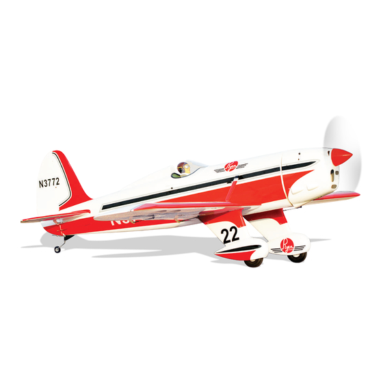
95% ALMOST READY TO FLY
SPECIFICATION:
- Wingspan: 2,350 mm (92.52 in).
- Length: 1,730 mm (68.11 in).
- Weight: 6 - 6.4 kg (13.2 - 14.1 lbs).
- Wing area: 80.7 dm .
- Wing loading: 74.35g/dm .
- Wing type: Naca Airfoil.
- Servo mount: 42mm x 21mm.
- Gear type: Oleo struts for main gear
and spring wire for tail gear (included).
- Spinner: 80mm.
Instruction Manual Book
®
Parts listing required (not included):
- Radio: 06 channels.
- Servo: 08 standard high torque servos.
- Engine: 120 - 2 stroke, 20 - 30cc Gas.
- Motor: Brushless outrunner 1800-2300W, 450KV.
- Propeller: Suit with your engine.
Recommended motor and battery set up (not included):
- Motor: Admiral GP20 6320-295kV
- Lipo cell: 6-8 cell (1 x 6 or 2 x 4 cells), 4000-5000mah
- ESC: 90-120A
- Receiver battery: 6V/ 800 - 1200mAh (2 packs).
Item code: BH72
Made in Vietnam.
Advertisement
Table of Contents

Related Manuals for Black Horse Model BH72


Summary of Contents for Black Horse Model BH72
- Page 1 Instruction Manual Book Item code: BH72 OLEO STRUTS LANDING GEAR. ALL BALSA - PLY WOOD CONSTRUCTION. ® COVERED WITH ORACOVER 95% ALMOST READY TO FLY SPECIFICATION: Parts listing required (not included): - Wingspan: 2,350 mm (92.52 in). - Radio: 06 channels.
-
Page 2: Table Of Contents
Thank you for purchasing Black Horse Model products. With over 18 years experience in production and fly testing, Black Horse Model is committed to bring the best quality products and good service to customers. Along with a team of creative engineers and skilled workers, we will always accompany with customers by our great experiences, fully enthusiasm... -
Page 3: Warranty
Please strictly follow the instruction manual to assemble work area thoroughly after working with berglass parts. and use this. In that Black Horse Model has no control over the nal SUGGESTION assembly or material used for nal assembly, Black Horse Model is not responsible for loss of use , or other incidental or consequential damages. -
Page 4: Covering Tools
Instruction manual RYAN Item code: BH72 ADHESIVES AND REQUIRED TOOLS FLIGHT WARNINGS When ready to y, rst extend the transmitter aerial. Thin CA Switch on the transmitter. 30-minute epoxy Switch on the receiver. 6-minute epoxy Check that the wings are correctly tted to the fuselage. - Page 5 Instruction manual RYAN Item code: BH72 • Officially designated AMA Air Show Teams (AST) are authorized to use devices and practices as defined within the Team AMA Program Document. (AMA Document #718.) (j) Not operate a turbine-powered aircraft, unless in compliance with the AMA turbine regulations. (AMA Document #510-A.)
-
Page 6: Parts Listing (Not Included)
Instruction manual RYAN Item code: BH72 PARTS LISTING (NOT INCLUDED) MOTOR Motor: Admiral GP20. Engine: NGH GT-25cc 2 stroke or NGH GF-30cc 4 stroke reccomended Servos Size: (39.9 x 20.1 x 38.1)mm. Torque: 4.8V (7.92kg/cm), 6V ( 9.43 kg/cm)..... 8 pcs. - Page 7 Instruction manual RYAN Item code: BH72 : Fuselage. : Wing panel (2a, 2b). : Horizontal stabilizer. : Rudder. : Aluminium wing dihedral brace. Canopy, 6b : Cockpit fuselage (6a: : Pilot). : Fuel tank (7a: Clunk, 7b: Stopper (three line).
-
Page 8: Preparation
Instruction manual RYAN Item code: BH72 PREPARATION ●Use a covering iron with a covering sock on high heat to tighten the covering if necessary. Apply pressure over sheeted areas to thoroughly bond the covering to the wood. INSTALLING THE AILERONS AND FLAPS... -
Page 9: Installing The Ailerons And Flaps Servos
Instruction manual RYAN Item code: BH72 <Bottom side> <Bottom side> INSTALLING THE AILERONS AND FLAPS SERVOS For Aileron servo. For Flap servo. <Bottom side> 4) Using the thread as a guide and using masking tape, tape the servo lead to the end of the thread: carefully pull the thread out. - Page 10 Instruction manual RYAN Item code: BH72 3mm Flat Screw Horn Ball link 3x15mm Tp Screw 2x10mm Tp Screw - - - - 4 - - - - - - - 6 - - - - 8 - - - - 2...
- Page 11 Instruction manual RYAN Item code: BH72 Aileron Aileron servos. 2 mm approx.16mm 3mm Flat Washer Aileron Aileron 3mm Hex Nut 3x12mm Cap Screw Aileron Aileron 1.5mm Screw 2x10mm Tp Screw Aileron 1.5mm Cut off shaded portion Drill holes using the stated.
- Page 12 Instruction manual RYAN Item code: BH72 For Flaps For Aileron Aileron Aileron Aileron 3x15mm Tp Screw Horn 3x12mm Cap Screw Aileron Aileron C . A Bottom View Flap Flap Flap 3x12mm 3x15mm Tp Screw Cap Screw Cut off shaded portion Horn carefully.
-
Page 13: Installing The Main Landing Gear
Instruction manual RYAN Item code: BH72 INSTALLING THE MAIN LANDING GEAR 3x10mm TP Screw 5x50mm Socket Head Cap Screw - - - 8 - - - 2 3x15mm TP Screw - - - 6 5mm Flat Washer - - - 2... - Page 14 Instruction manual RYAN Item code: BH72 3x15mm 3x15mm 2.5mm Bottom view 2.5mm 5mm Flat Washer 5x50mm Socket Head Cap Screw 3x10mm 3x10mm 2.5mm Bottom view Drill holes using the stated. 2.5mm (in this case 2.5mm Apply threadlocker Assemble left and right (screw cement).
- Page 15 Instruction manual RYAN Item code: BH72 Bottom view Bottom view...
-
Page 16: Installing The Fuselage Servos
Instruction manual RYAN Item code: BH72 INSTALLING THE FUSELAGE SERVOS 1) Install the rubber grommets and brass collets into the elevator, rudder and throottle servor. Test fit the servos into the servo tray. Trim the tray if necessary to fit your servos. -
Page 17: Horizontal Stabilizer Installation
Instruction manual RYAN Item code: BH72 HORIZONTAL STABILIZER INSTALLATION 1. Using a modeling knife, cut away the covering When you are sure that everything is aligned correctly, mix up a generous amount of 30 minute from the fuselage for the stabilizer and remove it. - Page 18 Instruction manual RYAN Item code: BH72 <Top side> Cut off shaded portion Apply instant glue Apply epoxy glue. carefully. (C.A glue, super glue).
-
Page 19: Rudder Installation
Instruction manual RYAN Item code: BH72 RUDDER INSTALLATION 67mm Pinned Hinge - - - - 5 Pinned Hinge <Top side> Cut off shaded portion Apply epoxy glue... -
Page 20: Installing The Rudder Linkages
Instruction manual RYAN Item code: BH72 INSTALLING THE RUDDER LINKAGES 3x12mm Cap Screw 3mm Flat Washer Horn - - - - - 1 Horn - - - - - - - - - - - - 1 3x12mm Cap Screw... -
Page 21: Installing The Elevator Linkage
Instruction manual RYAN Item code: BH72 <Top side> Rudder Servo Rudder Pushrod 3x12mm Screw Servo arm 3mm Flat washer Ball link Push rod 3mm Hex Nut Rudder Rudder Pushrod Rudder Servo INSTALLING THE ELEVATOR LINKAGES Repeat these step as installing the aileron linkages. - Page 22 Instruction manual RYAN Item code: BH72 Aluminium ball BOTTOM VIEW 3x15mm Tp Screw Horn 3x12mm Cap Screw Apply epoxy glue. The number of times Assemble left and right Cut off shaded portion the same way Assembly sides the same way carefully.
-
Page 23: Installing The Tail Gear
Instruction manual RYAN Item code: BH72 <Top side> Elevator Pushrod Elevator Servo Elevator Servo Elevator Pushrod 3x12mm Screw Servo arm 3mm Flat washer Ball link Push rod 3mm Hex Nut Elevator Pushrod Elevator Servo INSTALLING THE TAIL GEAR 3mm Collar... - Page 24 Instruction manual RYAN Item code: BH72 Drill holes using the stated. 2.5mm (in this case 2.5mm Cut off shaded portion carefully. Apply epoxy glue.
-
Page 25: Installing The Engine
Instruction manual RYAN Item code: BH72 INSTALLING THE ENGINE May be you also need to trim some wood from the tri-angle Using plate of plywood (supplied with the kit) mark the holes wood for the installation is easy. onto the fire wall for installing the engine mount for SIZE - 120 or DLE - 20CC , O.S - 22CC. - Page 26 Instruction manual RYAN Item code: BH72 4mm Hex Nut 500mm Pushrod wire - - - 1 - - - - - - - 4 Size: 120 M4 Blind Nut 4x25mm Cap Screw - - 4 - - - - - 8...
- Page 27 Instruction manual RYAN Item code: BH72 4mm Hex Nut <Top side> 4mm Flat Washer 4x25mm Cap Screw <Top side> Apply threadlocker (screw cement).
-
Page 28: Installing The Stopper
Instruction manual RYAN Item code: BH72 INSTALLING THE STOPPER Cut off shaded portion... -
Page 29: Installing The Fuel Tank
Instruction manual RYAN Item code: BH72 INSTALLING THE FUEL TANK 5. When satisfied with the alignment of the stopper assembly tighten the 3mm x 20mm machine screw until the rubber stopper expands and 1. Using a modeling knife, cut one length of silicon seals the tank opening. -
Page 30: Installing The Throttle
Instruction manual RYAN Item code: BH72 INSTALLING THE THROTTLE direction. When the throttle stick is moved forward from idle to full throttle, the throttle barrel should Connector - - - - - - - - - 1 also open and close using this motion. If not, reverse the direction of the servo, using the transmitter. -
Page 31: Mounting The Cowl
Instruction manual RYAN Item code: BH72 INSTALLING THE COWLING four 1,6mm pilot holes through both the cowl and the 1) Remove the mu er and needle valve assembly from side edges of the rewall. the engine. Slide the berglass cowl over the engine. - Page 32 Instruction manual RYAN Item code: BH72 <Top side> C . A 2 m m 3x12mm Tp Screw <Top side> C . A 2 m m 3x12mm Tp Screw...
-
Page 33: Installing The Electric Motor (Ep Version)
Instruction manual RYAN Item code: BH72 INSTALLING THE ELECTRIC MOTOR (EP VERSION) 4x70mm Socket Head M4 Blind Nut Cap Screw - - - - - 4 - - 4 4mm Flat Washer 4x30mm Socket Head - - - - - - - - 4... -
Page 34: Installing The Receiver And Battery
Instruction manual RYAN Item code: BH72 145mm <Top side> INSTALLING THE RECEIVER & BATTERY INSTALLING THE SWITCH Plug the servo leads and the switch lead into the 1) The switch should be mounted on the fuselage side, receiver. You may want to plug an aileron extension into... -
Page 35: Installing The Wing Fuselage
Instruction manual RYAN Item code: BH72 INSTALLING THE WING FUSELAGE Aluminium tube. 25mm 797mm Test t the aluminium tube dihedral brace into each wing haft. The brace should slide in easily. If not, use 220 grit sand around the edges and ends of the brace until it ts properly. -
Page 36: Installing The Wing Struts Set
Instruction manual RYAN Item code: BH72 -The wings must be inserted and attached completely before xing with crew. 4x12mm <Top side> INSTALLING THE WING STRUTS SET Ball Link 3x6mm Button Head Cap Screw - - - - - - - 4... - Page 37 Instruction manual RYAN Item code: BH72 2.6mm 2.6mm 3x6mm Button Head 3x6mm Button Head Cap Screw Cap Screw Drill holes using the stated. Apply epoxy glue. 2.6mm (in this case 2.6mm...
-
Page 38: Installing Cockpit Fuselage
Instruction manual RYAN Item code: BH72 3x12mm Cap Screw 3mm Spring Washer 3x12mm Cap Screw 3mm Spring Washer <Top side> 3x12mm Cap Screw 3mm Spring Washer Assemble left and right sides the same way. INSTALLING COCKPIT FUSELAGE Canopy Pilot - - - - - - - 1 - - - - - - - 1 <Top side>... - Page 39 Instruction manual RYAN Item code: BH72 <Top side> Adhesive tape <Top side> <Top side> Adhesive tape Apply epoxy glue.
-
Page 40: Installing The Propeler & Spinner
Instruction manual RYAN Item code: BH72 INSTALLING THE PROPELER & SPINNER 3x12mm TP Screw - - - - - 4 Use the spacer suitable 3x12mm TP Screw Must be purchased Fully tighten separately! -
Page 41: Balancing
Instruction manual RYAN Item code: BH72 BALANCING CONTROL THROWS 1) It is critical that your airplane be balanced correctly. We highly recommend setting up a plane using the Improper balance will cause your plane to lose control control throws listed. -
Page 42: For Your Radio Installation Basic Connection For Airplane And Adjustment Of Servos
Instruction manual RYAN Item code: BH72 FOR YOUR RADIO INSTALLATION BASIC CONNECTION FOR AIRPLANE AND ADJUSTMENT OF SERVOS Example of connection ●For more information, refer to radio system instruction manual. ●Follow instruction manual of Engine and Battery. Aileron Servo Aileron... -
Page 43: Main Gear Dimensional Detail
Instruction manual RYAN Item code: BH72 MAIN GEAR DIMENSIONAL DETAIL 60mm 60mm 46mm TAIL GEAR DIMENSIONAL DETAIL 53mm 28mm ø1.5mm ø1.5mm ø2.5mm... -
Page 44: Decoration
Instruction manual RYAN Item code: BH72 DECORATION < Top view > RYAN- N 3 7 7 2 < Bottom view > N3772 < Side view > Left N3772 < Side view > Right RYAN- N 3 7 7 2 N3772... -
Page 45: Exploded View
Instruction manual RYAN Item code: BH72 EXPLODED VIEW... -
Page 46: I/C Flying Warning
I/C FLYING WARNING Always operate in open areas, away from NEVER fly near power lines,aerials or ALWAYS adjust the engine from behind factories, hospitals, schools, buildings other dangerous areas including airports, the propeller, and do not allow any part and houses etc. NEVER fly your aircraft motorways etc. -
Page 47: I/C Flying Guide
I/C FLYING GUIDE Operate the control sticks on the ALWAYS land the model INTO When ready to fly, first extend transmitter and check that the th e wind , this en su res tha t th e the transmitter aerial. control surfaces move freely and in model lands at the slowest possible the CORRECT directions.
Need help?
Do you have a question about the BH72 and is the answer not in the manual?
Questions and answers