Table of Contents
Advertisement
Available languages
Available languages
Advertisement
Chapters
Table of Contents

Subscribe to Our Youtube Channel
Related Manuals for HBM T40FH


Summary of Contents for HBM T40FH
- Page 1 Mounting Instructions | Montageanleitung English Deutsch T40FH...
- Page 2 Tel. +49 6151 803-0 Fax +49 6151 803-9100 info@hbm.com www.hbm.com Mat.: 7-2002.4429 DVS: A4429-3.0 HBM: public 09.2017 E Hottinger Baldwin Messtechnik GmbH. Subject to modifications. All product descriptions are for general information only. They are not to be understood as a guarantee of quality or durability.
- Page 3 Mounting Instructions | Montageanleitung English Deutsch T40FH...
-
Page 4: Table Of Contents
....... . Contents of the TEDS memory as defined in IEEE 1451.4 ..T40FH A4429-3.0 HBM: public... - Page 5 ..........13.1 T40FH torque transducer with rotational speed measuring system, Option 4, Code SU2, DU2, HU2 .
-
Page 6: Safety Instructions
The FCC ID, that is to say, the unique identifier, must be visible on the device. Model Measuring ranges FCC ID 100 kNm, 130 kNm, T40S10 150 kNm 2ADAT−T40S10TOS11 12438A−T40S10TOS11 200 kNm, 250 kNm, T40S11 300 kNm T40FH A4429-3.0 HBM: public... - Page 7 (1) This device may not cause harmful interference, and (2) this device must accept any interference received, including interference that may cause un desired operation. Fig. 1.2 Example of a label This device complies with Industry Canada standard RSS210. T40FH A4429-3.0 HBM: public...
- Page 8 Appropriate use The T40FH torque flange is used exclusively for torque, angle of rotation and power measurement tasks within the load limits stipulated in the specifications. Any other use is not appropriate.
- Page 9 This requires additional components and constructive measures, for which the installer and operator of the plant is responsible. The electronics conditioning the measurement signal should be designed so that measurement signal failure does not subsequently cause damage. T40FH A4429-3.0 HBM: public...
- Page 10 Any modification shall exclude all liability on our part for any damage resulting therefrom. Selling on If the torque flange is sold on, these mounting instructions must be included with the torque flange. T40FH A4429-3.0 HBM: public...
- Page 11 3. As commissioning engineers or service engineers, you have successfully completed the training to repair the automation systems. You are also authorized to operate, ground and label circuits and equipment in accor dance with safety engineering standards. T40FH A4429-3.0 HBM: public...
-
Page 12: Markings Used
CE mark The CE mark enables the manufacturer to guarantee that the product complies with the requirements of the rele vant EC directives (the Declaration of Conformity can be found on the HBM website www.hbm.com under HBMdoc). Example of a label Example of a label with FCC ID and IC number. -
Page 13: The Markings Used In This Document
This marking draws your attention to information about the product or about handling the product. Information Emphasis Italics are used to emphasize and highlight text and See … identify references to sections, diagrams, or external documents and files. T40FH A4429-3.0 HBM: public... -
Page 14: Application
Application Application The T40FH torque flange measures static and dynamic torques on stationary and rotating shafts. Test beds can be extremely compact because of the com pact design of the transducer. This offers a very wide range of applications. The T40FH torque flange is reliably protected against electromagnetic interfer... -
Page 15: Structure And Mode Of Operation
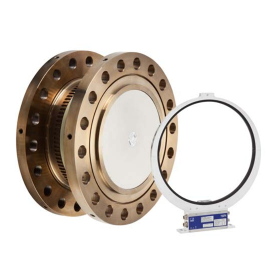
The antenna segments (ring) should be mounted concentrically around the rotor (see Chapter 5). Rotor Antenna segments Connector Connector plugs plugs Stator housing Type plate Fig. 4.1 Mechanical construction T40FH A4429-3.0 HBM: public... - Page 16 The rotational speed sensor is mounted on the stator in Option 5 with a rota tional speed measuring system. Rotational speed is measured magnetically by a magnetic field dependent resistor and a ring gear attached to the rotor. T40FH A4429-3.0 HBM: public...
-
Page 17: Mechanical Installation
S Comply with the mounting dimensions to enable correct operation. An appropriate shaft flange enables the T40FH torque flange to be mounted directly. It is also possible to mount a joint shaft or relevant compensating ele... -
Page 18: Conditions On Site
Mechanical installation no circumstances should the permissible limits specified for bending moments, lateral and longitudinal forces be exceeded. Due to the T40FH torque flange's high torsional stiffness, dynamic shaft train changes are kept to a minimum. Important Even if the unit is installed correctly, the zero point adjustment made at the fac... -
Page 19: Installation Options
If access to the rotor in its installed state is difficult, we recommend mounting the antenna ring beforehand. It is essential in this case to comply with the notes on assembling the antenna segments (see Section 5.7). T40FH A4429-3.0 HBM: public... -
Page 20: Installation With Antenna Ring Removed
2 Fit the stator mounting 3 Remove one antenna segment 4 Fit the antenna segment around the shaft train Support supplied by customer Clamp fixture 5 Align and fully assemble the stator 6 Fit the clamp fixture T40FH A4429-3.0 HBM: public... -
Page 21: Preparing For The Rotor Mounting
1. Remove the top layer of foam packaging. Fig. 5.1 T40FH packaging 2. Fasten two equal-length ropes with sufficient load-carrying capacity to the eyebolts (each of the two ropes must be able to bear the full weight of the rotor) and hoist the rotor out of its packaging with the crane (see Fig. - Page 22 6. Carefully tilt the rotor by lowering it over the flange edge until it rests hori zontally on both outer flange surfaces (see Fig. 5.3). CAUTION Crush hazard. Keep your hands and feet a safe distance away from the rotor. T40FH A4429-3.0 HBM: public...
- Page 23 8. Screw the second eyebolt back into the tapped holes in the outer flange sur face. 9. Fasten the rotor to the hook of the crane with two equal-length ropes. The rotor is now prepared for horizontal installation (see Fig. 5.4). T40FH A4429-3.0 HBM: public...
-
Page 24: Mounting The Rotor
You can then refer to them whenever there is anything you wish to know, such as the shunt signal. To explicitly assign the data, the identification number and the size are engraved on the rotor flange, where they can be seen from outside. T40FH A4429-3.0 HBM: public... - Page 25 2. For connection of the flange, (see Fig. 5.5) use hexagon screws DIN 933 of a suitable length (dependent on the connection geometry, see Tab. 5.1 on Page 24). 3. Fasten all screws with the specified torque (Tab. 5.1 on Page 24). T40FH A4429-3.0 HBM: public...
- Page 26 Measure Fastening screws Number of Prescribed ment tightening moment screws per range flange kNVm Property class 2450 12.9 4250 DIN 933; black/oiled/m =0.125 Tab. 5.1 Fastening screws T40FH A4429-3.0 HBM: public...
-
Page 27: Installing The Stator
(M4+M5) screws with washers (M4+M5) upper Antenna segments lower Stator housing Fig. 5.6 Bolted connection of the antenna segments on the stator 1. Undo and remove both the bolted connections (M4+M5) on the upper antenna segment. T40FH A4429-3.0 HBM: public... - Page 28 Depending on the operating conditions, stator oscillation may be induced. This effect is dependent on: S the rotational speed, S the antenna diameter (depends in turn on the measuring range), S the construction of the machine base. T40FH A4429-3.0 HBM: public...
- Page 29 7. Fasten the clamp fixture with the enclosed bolted connection, as shown in Fig. 5.8. Clamp a suitable support element (we recommend a Ø 3-6 mm threaded rod) between the upper and lower parts of the clamp fixture and tighten the clamping screws. T40FH A4429-3.0 HBM: public...
- Page 30 Mechanical installation Support supplied by customer Clamp fixture Antenna ring Fig. 5.8 Supporting the antenna ring Fig. 5.9 Construction example for plug clamps (for two plugs) T40FH A4429-3.0 HBM: public...
-
Page 31: Rotational Speed Measuring System
Page 60). Stator alignment (rotational speed measuring system) For measuring mode to operate perfectly, the speed sensor must be placed at a defined position to the rotor ring gear. When the radial and axial alignment of T40FH A4429-3.0 HBM: public... - Page 32 The nominal radial distance is crucial for radial alignment (see Fig. 5.11). The optimum distance is 2.5 mm and is achieved when the rotor and the stator are in precise radial alignment. T40FH A4429-3.0 HBM: public...
-
Page 33: Electrical Connection
S All plug connections or swivel nuts must be fully tightened. Important Transducer connection cables from HBM with attached connectors are marked in accordance with their intended purpose (Md or n). When cables are short ened, inserted into cable ducts or installed in control cabinets, this marking can be lost or hidden. -
Page 34: Connector Pin Assignment Option 4, Code Su2, Du2, Hu2
Electrical connection Electrical and magnetic fields often induce interference voltages in the measur ing circuit. Therefore: S Use shielded, low-capacitance measurement cables only (HBM cables fulfill both conditions). S Only use plugs that meet EMC guidelines. S Do not route the measurement cables parallel to power lines and control circuits. - Page 35 RS-422 complementary signals; with cable lengths exceeding 10 m, we recommend using a termination resistor R = 120 ohms between the (wh) and (rd) wires. RS‐422: Pin 1 corresponds to A, Pin 4 corresponds to B. T40FH A4429-3.0 HBM: public...
- Page 36 Electrical connection Notice Torque flanges are only intended for operation with a DC supply voltage. They must not be connected to older HBM amplifiers with square-wave excitation. This could destroy the connection board resistors or cause other faults in the amplifiers.
- Page 37 R = 120 ohms. For KAB163 / KAB164 color code brown (bn) Pin 1 Pin 6 Pin 3 Pin 7 Fig. 6.1 Speed signals at connector 2 (rotational speed in the direction of the arrow) T40FH A4429-3.0 HBM: public...
- Page 38 Supply voltage 18 V … 30 V Torque measurement signal (voltage output; ±10 V) Not in use Shunt signal trigger 5 V … 30 V Top view Shunt signal 0 V; Shield connected to housing ground T40FH A4429-3.0 HBM: public...
-
Page 39: Connector Pin Assignment Option 3, Code Pnj
Connect a safety extra-low voltage of 18 V … 30 V to pin 3 (+) and pin 2 ( ) of connectors 1 or 3. We recommend that you use HBM cable KAB Distribution system for electrical energy with greater physical expansion (over several test benches, for example) that may possibly also supply consumers with high nominal (rated) currents. -
Page 40: Supply Voltage (Option 3, Code Pnj)
Supply voltage (Option 3, Code PNJ) A pre-wired 6-wire transducer connection cable with free ends is available as an accessory. Extension cables should be shielded and low capacitance. HBM provides spe cific cables for this purpose, the 1-KAB0304A-10 (pre-wired) and the KAB8/00-2/2/2 (by the meter). -
Page 41: Teds Transducer Identification (Option 3, Code Pnj)
The digital identification system is available at plug connection PIN 7 to PIN 2. The HBM TEDS Editor is used to store the data. This is a component of the HBM "MGCplus Setup Assistant" software. You can use the Editor to manage different user rights, thus protecting the essential transducer data from being overwritten by mistake. -
Page 42: Contents Of The Teds Memory As Defined In Ieee 1451.4
The base area (basic TEDS), to the configuration defined in standard IEEE 1451.4. The transducer type, the manufacturer and the transducer serial num ber are contained here. Example: TEDS content with the identity number for the T40FH/150 kN@m sensor with serial no. 123456, made in November 2005 TEDS transducer identification Manufacturer... - Page 43 Bridge type Full The bridge type. "Full" for a full bridge. Impedance of 1550+-100 Input resistance accord each bridge ele ing to the HBM data ment sheet Response time 1.0000000u Of no significance to HBM transducers Excitation Level Nominal (rated) excita...
- Page 44 Excitation Level Lower limit for the oper ating range of the excita (Minimum) tion voltage according to the HBM data sheet. Excitation Level 12.0 Upper limit for the oper ating range of the excita (Maximum) tion voltage according to the HBM data sheet.
- Page 45 HBM Channel Comment tem plate can also be used for this purpose. Typical values for an HBM T40FH/150 kN@m torque flange Template: HBM Channel Name Channel name T40FH/150 kNm When creating the Bridge Sensor template, the manufacturer defines the physi...
-
Page 46: Shunt Signal
Shunt signal Shunt signal The T40FH torque flange delivers an electrical shunt signal that can be acti vated from the amplifier for measuring chains with HBM components. The transducer generates a shunt signal of about 50% of the nominal (rated) torque;... -
Page 47: Functionality Testing
Rotor status, LED A (upper LED) Color Significance Green (pulsating) Internal rotor voltage values o.k. Flashing orange Rotor and stator mismatched (an increasing flashing fre quency indicates the degree of misalignment) => Correct the rotor/stator alignment. T40FH A4429-3.0 HBM: public... -
Page 48: Stator Status, Led B (Lower Led)
(f = 0 Hz, U = defect level). => Correct the rotor/stator alignment. Internal stator defect, the measurement signals reflect the (permanently lit) level of the fault (f = 0 Hz, U = defect level). T40FH A4429-3.0 HBM: public... -
Page 49: Load-Carrying Capacity
The torque flange can be used to measure static and dynamic torques. The following apply to the measurement of dynamic torque: S The T40FH calibration performed for static measurements is also valid for dynamic torque measurements. S The natural frequency f... -
Page 50: Maintenance
Maintenance Nominal (rated) torque M as a % Oscillation bandwidth Oscillation bandwidth 200% oscillation bandwidth Time t Oscillation bandwidth Fig. 10.1 Permissible dynamic loading Maintenance T40FH torque flanges are maintenance free. T40FH A4429-3.0 HBM: public... -
Page 51: Waste Disposal And Environmental Protection
Packaging The original packaging of HBM devices is made from recyclable material and can be sent for recycling. Store the packaging for at least the duration of the warranty. In the case of complaints, the torque flange must be returned in the original packaging. -
Page 52: Dimensions
Dimensions Dimensions 13.1 T40FH torque transducer with rotational speed measuring system, Option 4, Code SU2, DU2, HU2 13.1.1 T40FH 100 kNm - 150 kNm Dimensions in mm (1 mm = 0.03937) Dimensions without tolerances, per DIN ISO 2768-mk For axial Ø... - Page 53 Dimensions Dimensions in mm (1 mm = 0.03937) Dimensions without tolerances, per (120) DIN ISO 2768-mk 89.5 Partial sections cut A-A T40FH A4429-3.0 HBM: public...
-
Page 54: 13.1.2 T40Fh 200 Knm - 300 Knm
Dimensions 13.1.2 T40FH 200 kNm - 300 kNm Dimensions in mm (1 mm = 0.03937) Dimensions without tolerances, per DIN ISO 2768-mk For axial 22° Ø 6.5 locking 18x20°=360° approx. For connecting cable incl. plug T40FH A4429-3.0 HBM: public... - Page 55 Dimensions Dimensions in mm (1 mm = 0.03937) Dimensions without tolerances, per (150) DIN ISO 2768-mk Partial sections cut A-A T40FH A4429-3.0 HBM: public...
-
Page 56: T40Fh Torque Transducer (Non-Rotating)
Dimensions 13.2 T40FH torque transducer (non-rotating), Option 4, Code PNJ 13.2.1 T40FH 100 kNm - 150 kNm Dimensions in mm (1 mm = 0.03937) Dimensions without tolerances, per DIN ISO 2768-mk 22.5° 16x22.5°=360° (120) Ø395 Partial sections cut A-A T40FH... - Page 57 Dimensions Dimensions in mm (1 mm = 0.03937) Dimensions without tolerances, per DIN ISO 2768-mk 22.5° 16x22.5°=360° 10.5° Min. bending Ø30.5 radius R=20 75.5° Ø18 Ø395 Partial sections cut B-B T40FH A4429-3.0 HBM: public...
-
Page 58: 13.2.2 T40Fh 200 Knm - 300 Knm
Dimensions 13.2.2 T40FH 200 kNm - 300 kNm Dimensions in mm (1 mm = 0.03937) Dimensions without tolerances, per DIN ISO 2768-mk 20° (150) 18x20°=360° 99.4 Ø470 Partial sections cut A-A T40FH A4429-3.0 HBM: public... - Page 59 Dimensions Dimensions in mm (1 mm = 0.03937) 20° Dimensions without tolerances, per DIN ISO 2768-mk 18x20°=360° 0.5° Min. bending Ø37 radius R=20 Ø18 Ø470 Partial sections cut B-B T40FH A4429-3.0 HBM: public...
-
Page 60: Ordering Numbers, Accessories
Without rotational speed measuring system Magnetic rotational speed measuring system Code Option 6: Customized modification No customer modification = PREFERRED TYPES K-T40FH - 1 0 0 R - M F - S - D U 2 - 0 - S T40FH A4429-3.0 HBM: public... - Page 61 TIM40/TMC connection cable, 6 m 1-KAB174-6 Cable sockets 423G-7S, 7-pin (straight) 3-3101.0247 423W-7S, 7-pin (angle) 3-3312.0281 423G-8S, 8-pin (straight) 3-3312.0120 423W-8S, 8-pin (angle) 3-3312.0282 Connection cable, by the meter (min. order quantity: 10 m, price per meter) Kab8/00-2/2/2 4-3301.0071 T40FH A4429-3.0 HBM: public...
-
Page 62: Specifications
Frequency output ≤±0.02 Voltage output ≤±0.02 Temperature effect per 10 K in the nominal (rated) temperature range on the output signal, related to the actual value of the signal span Frequency output ≤±0.1 Voltage output ≤±0.1 T40FH A4429-3.0 HBM: public... - Page 63 (5 V balanced at negative nominal (rated) torque / 30 / 120 (5 V balanced Voltage output at positive nominal (rated) torque at negative nominal (rated) torque Load resistance Frequency output kΩ ≥2 Voltage output kΩ ≥10 T40FH A4429-3.0 HBM: public...
- Page 64 50 % of M Tolerance of the shunt signal, <±0.05 related to M Nominal (rated) trigger voltage Trigger voltage limit min. >2.5 Shunt signal ON max. <0.7 Shunt signal OFF Torque measuring system (non-rotating) Accuracy class T40FH A4429-3.0 HBM: public...
- Page 65 TEDS as per IEEE 1451.4 Rotational speed measuring system Rotational speed measuring system Magnetic scanning and ring gear Output signals 2 square wave signals 90° phase shifted, 5V TTL/RS-422 Number of pulses per revolution (number of teeth) T40FH A4429-3.0 HBM: public...
- Page 66 Air discharge Fast transients (burst) Impulse voltages (surge) Conducted interference (AM) Degree of protection per EN 60 529 IP 54 ° Reference temperature ° +10 … +70 Nominal temperature range ° -20 … +85 Operating temperature range T40FH A4429-3.0 HBM: public...
- Page 67 0.072 0.075 Stiffness in the axial direction c kN/mm 1855 3900 Stiffness in the radial direction c kN/mm 3340 4910 Stiffness during the bending kN⋅m/rad 25495 65900 moment round a radial axis c kN⋅m/ 1150 degrees T40FH A4429-3.0 HBM: public...
- Page 68 (side of the flange with external centering) Max. permissible static eccentricity of the rotor (radially) to the center point of the stator without the speed module ±2 with rotational speed module ±1 T40FH A4429-3.0 HBM: public...
- Page 69 The influence of radial run-out deviations, eccentricity, defects of form, notches, marks, local residual magnetism, structural inhomogeneity or material anomalies needs to be taken into account and isolated from the actual undulation. Above the nominal (rated) temperature range: ±1.5 mm. T40FH A4429-3.0 HBM: public...
-
Page 70: Supplementary Technical Information
Surface quality of the axial and radial run-out tolerances (A, B and AB) To ensure that the torque flange retains its characteristics once it is installed, we recommend that the customer also chooses the specified form and position tolerances, surface quality and hardness for the connections provided. T40FH A4429-3.0 HBM: public... - Page 71 Mounting Instructions | Montageanleitung English Deutsch T40FH...
- Page 72 ....... Inhalt des TEDS‐Speicher nach IEEE 1451.4 ....T40FH A4429-3.0 HBM: public...
- Page 73 ......13.1.1 T40FH 100 kNm - 150 kNm ....... . .
-
Page 74: Sicherheitshinweise
Betriebsverhalten zur Folge haben können. Die FCC-Kennung bzw. die eindeutige Kennung muss am Gerät sichtbar sein. Modell Messbereiche FCC ID 100 kNm, 130 kNm, T40S10 150 kNm 2ADAT−T40S10TOS11 12438A−T40S10TOS11 200 kNm, 250 kNm, T40S11 300 kNm T40FH A4429-3.0 HBM: public... - Page 75 (1) This device may not cause harmful interference, and (2) this device must accept any interference received, including interference that may cause undesired operation. Abb. 1.2 Beispiel eines Labels Dieses Gerät entspricht der Industry-Canada-Norm RSS210. T40FH A4429-3.0 HBM: public...
- Page 76 (2) cet appareil doit accepter toute interférence, notamment les interférences qui peuvent affecter son fonction nement. Bestimmungsgemäße Verwendung Der Drehmoment‐Messflansch T40FH ist für Drehmoment‐, Drehwinkel‐ und Leistungs‐Messaufgaben im Rahmen der durch die technischen Daten spezifi zierten Belastungsgrenzen konzipiert. Jeder andere Gebrauch ist nicht bestim mungsgemäß.
- Page 77 S Abdeckung oder Verkleidung sollen sowohl Quetsch‐ und Scherstellen vermeiden als auch vor evtl. sich lösenden Teilen schützen. S Abdeckungen und Verkleidungen müssen weit genug von den bewegten Teilen entfernt oder so beschaffen sein, dass man nicht hindurchgreifen kann. T40FH A4429-3.0 HBM: public...
- Page 78 (Unfallverhütungsvorschriften der BG) beim Umgang mit dem Aufnehmer, kann der Aufnehmer beschädigt oder zerstört werden. Insbesondere bei Überlas tungen kann es zum Bruch des Aufnehmers kommen. Durch den Bruch können darüber hinaus Sachen oder Personen in der Umgebung des Aufnehmers zu Schaden kommen. T40FH A4429-3.0 HBM: public...
- Page 79 3. Sie sind Inbetriebnehmer oder für den Service eingesetzt und haben eine Ausbildung absolviert, die Sie zur Reparatur der Automatisierungsanlagen befähigt. Außerdem haben Sie eine Berechtigung, Stromkreise und Geräte gemäß den Normen der Sicherheitstechnik in Betrieb zu nehmen, zu erden und zu kennzeichnen. T40FH A4429-3.0 HBM: public...
-
Page 80: Verwendete Kennzeichnungen
Angaben in dieser Anleitung nachlesen und berücksichtigen CE‐Kennzeichnung Mit der CE‐Kennzeichnung garantiert der Hersteller, dass sein Produkt den Anforderungen der relevanten EG‐ Richtlinien entspricht (die Konformitätserklärung finden Sie auf der Website von HBM www.hbm.com unter HBM doc). Beispiel eines Labels Beispiel eines Labels mit FCC-ID und IC-Nummer. -
Page 81: In Dieser Anleitung Verwendete Kennzeichnungen
Sie nützliche Informationen hin. Tipp Diese Kennzeichnung weist auf Informationen zum Produkt oder zur Handhabung des Produktes hin. Information Hervorhebung Kursive Schrift kennzeichnet Hervorhebungen im Siehe … Text und kennzeichnet Verweise auf Kapitel, Bilder oder externe Dokumente und Dateien. T40FH A4429-3.0 HBM: public... -
Page 82: Anwendung
Wellen. Der Aufnehmer ermöglicht durch seine kurze Bauweise äußerst kompakte Prüfaufbauten. Dadurch ergeben sich vielfältige Anwendungen. Der Drehmomentflansch T40FH verfügt über einen zuverlässigen Schutz vor elektromagnetischen Störungen. Er wurde gemäß harmonisierten euro päischen Normen getestet und/oder entspricht US-amerikanischen und kanadischen Normen. -
Page 83: Aufbau Und Wirkungsweise
Am Stator befinden sich Anschlussstecker für das Drehmoment‐ und das Dreh zahlsignal, die Spannungsversorgung und den digitalen Ausgang. Die Anten nensegmente (der Antennenring) müssen konzentrisch um den Rotor montiert werden (siehe Kapitel 5). Antennen Rotor segmente Anschluss Anschlussstecker stecker Statorgehäuse Typenschild Abb. 4.1 Mechanischer Aufbau T40FH A4429-3.0 HBM: public... - Page 84 Aufbau und Wirkungsweise Bei der Option 5 mit Drehzahlmesssystem ist auf dem Stator der Drehzahlsen sor montiert. Die Drehzahlmessung erfolgt magnetisch mittels Feldplatten sensor und einem am Rotor angebrachten Zahnkranz. T40FH A4429-3.0 HBM: public...
-
Page 85: Mechanischer Einbau
S Kleben Sie die Verbindungsschrauben mit einer Schraubensicherung (mit telfest, z. B. von LOCTITE) in das Gegengewinde ein, um einen Vorspann verlust durch Lockern auszuschließen, falls Wechsellasten zu erwarten sind. S Halten Sie die Montagemaße unbedingt ein, um einen einwandfreien Betrieb zu ermöglichen. T40FH A4429-3.0 HBM: public... -
Page 86: Bedingungen Am Einbauort
Bei Rechtsdrehmoment (im Uhrzeigersinn) beträgt die Ausgangsfrequenz bei Option 5, Code DU2 60 … 90 kHz (Option 5, Code SU2: 10 … 15 kHz; Option HU2: 240 … 360 kHz). In Verbindung mit Messverstärkern von HBM oder bei T40FH A4429-3.0 HBM: public... -
Page 87: Einbaumöglichkeiten
Nutzung des Spannungsausgangs steht ein positives Ausgangssignal (0 V … +10 V) an. Beim Drehzahl‐Messsystem ist zum eindeutigen Bestimmen der Drehrichtung auf dem Statorgehäuse ein Pfeil angebracht: Dreht der Mess flansch in Pfeilrichtung, liefern angeschlossene HBM‐Messverstärker ein posi tives Ausgangssignal. Bei der nichtdrehenden Ausführung ist bei Rechtsdrehmoment das Ausgangs... -
Page 88: Einbau Mit Demontiertem Antennenring
Mechanischer Einbau 5.4.1 Einbau mit demontiertem Antennenring Kundenseitige Befestigung 1. Rotor installieren 2. Statorbefestigung montieren 3. Ein Antennensegment demontieren 4. Antennensegment um den Wellenstrang montieren Kundenseitige Abstützung Klemmstück 5. Stator ausrichten und fertig montieren 6. Klemmstück montieren T40FH A4429-3.0 HBM: public... -
Page 89: Rotormontage Vorbereiten
Sie Sicherheitsschuhe. 1. Entfernen Sie die obere Schaumstofflage der Verpackung. Abb. 5.1 Verpackung des T40FH 2. Befestigen Sie an den Hebeösen zwei gleich lange Seile mit ausreichender Tragfähigkeit (jedes der zwei Seile muss das volle Rotorgewicht tragen kön... - Page 90 4. Entfernen Sie eine Hebeöse. 5. Heben Sie den Rotor vorsichtig an, bis er frei hängt. 6. Kippen Sie den Rotor vorsichtig beim Ablassen über die Flanschkante, bis er auf beiden Flanschaußenflächen waagerecht steht (siehe Abb. 5.3). T40FH A4429-3.0 HBM: public...
- Page 91 8. Schrauben Sie die zweite Hebeöse wieder in die Gewindebohrungen in der Flanschaußenfläche ein. 9. Befestigen Sie den Rotor mit zwei gleich langen Seilen am Kranhaken. Der Rotor ist nun für einen horizontalen Einbau vorbereitet (siehe Abb. 5.4). T40FH A4429-3.0 HBM: public...
-
Page 92: Montage Des Rotors
Sie auf den Stator oder andere relevante Prüfstandskomponenten auf kleben können. Sie können dann jederzeit die für Sie interessanten Daten ablesen, z. B. das Shuntsignal. Für die eindeutige Zuordnung der Daten ist am Rotorflansch von außen sichtbar eine Identifikationsnummer und die Baugröße eingraviert. T40FH A4429-3.0 HBM: public... - Page 93 Messzone Sechskantschraube DIN 933 Abb. 5.5 Verschraubung des Rotors 2. Verwenden Sie für die Verschraubung des Flanschs (siehe Abb. 5.5) Sechskantschraube DIN 933 in geeigneter Länge (abhängig von der Anschlussgeometrie, siehe Tab. 5.1 auf Seite 24). T40FH A4429-3.0 HBM: public...
- Page 94 Andernfalls kann es zu erheblichen Messfehlern durch Drehmomentneben schluss oder zur Beschädigung des Aufnehmers kommen. Mess Befestigungsschrauben Vorgeschriebenes Anzahl der bereich Schrauben Anzugsmoment pro Flansch kNVm Festigkeitsklasse 2450 12.9 4250 DIN 933; schwarz/geölt/m =0,125 Tab. 5.1 Befestigungsschrauben T40FH A4429-3.0 HBM: public...
-
Page 95: Montage Des Stators
Montage des Stators zu ermöglichen. Bohrung Ø 6,5 mm zur Fixierung des Antennensegments Antennensegment‐ Schrauben mit Antennensegment‐ Unterlegscheiben Schrauben mit (M4+M5) Unterlegscheiben (M4+M5) oben Antennensegmente unten Statorgehäuse Abb. 5.6 Verschraubung der Antennensegmente am Stator T40FH A4429-3.0 HBM: public... - Page 96 Um die Ausrichtung zu erleichtern, sollten die Außenkante des Sta tor‐Antennensegments und die Außenkante des Stator‐Wicklungsträgers auf einer Linie liegen (fluchten). Beachten Sie die in den technischen Daten angegebenen zulässigen Ausrichtungstoleranzen. 6. Ziehen Sie jetzt die Verschraubung des Statorgehäuses fest an. T40FH A4429-3.0 HBM: public...
- Page 97 Hierzu befindet sich am oberen Antennensegment Bohrung mit einem Durch messer von 6,5 mm, die zur Aufnahme der Klemmeinrichtung dient (siehe Abb. 5.7). Gleichzeitig ist in diesem Fall eine Abstützung der Kabelstecker (nicht im Liefe rumfang enthalten) erforderlich, ein Konstruktionsbeispiel zeigt Abb. 5.9. T40FH A4429-3.0 HBM: public...
- Page 98 7. Befestigen Sie das klemmstück mit der beigelegten Verschraubung nach Abb. 5.8. Klemmen Sie ein geeignetes Abstützelement (z.B. einen Gewindestab Ø 3 - 6 mm) zwischen Ober- und Unterteil des Klemmstücks und ziehen Sie die Klemmschrauben an. T40FH A4429-3.0 HBM: public...
- Page 99 Mechanischer Einbau Kundenseitige Abstützung Klemmstück Antennenring Abb. 5.8 Abstützen des Antennenrings Abb. 5.9 Konstruktionsbeispiel für Steckerklemmen (für zwei Stecker) T40FH A4429-3.0 HBM: public...
-
Page 100: Drehzahlmesssystem
Feldstärke nicht überschritten wird (siehe Kapitel 15 „Technische Daten“, Seite 61). Ausrichtung Stator (Drehzahlmesssystem) Für den einwandfreien Messbetrieb muss der Drehzahlsensor an einer definierten Stelle zum Zahnkranz des Rotors positioniert werden. Bei exakter T40FH A4429-3.0 HBM: public... - Page 101 Rotorachse und Achse des Drehzahlsensors müssen in einer Linie rechtwinklig zur Statorplattform stehen. Für die radiale Ausrichtung ist der radiale Nenn abstand maßgebend (siehe Abb. 5.11). Der optimale Abstand beträgt 2,5 mm und wird erreicht, wenn Rotor und Stator exakt radial zueinander ausgerichtet sind. T40FH A4429-3.0 HBM: public...
-
Page 102: Elektrischer Anschluss
S Alle Kabel‐Steckverbindungen oder Überwurfmuttern müssen fest angezo gen werden. Wichtig Aufnehmer‐Anschlusskabel von HBM mit montierten Steckern sind ihrem Verwendungszweck entsprechend gekennzeichnet (Md oder n). Beim Kürzen der Kabel, Einziehen in Kabelkanälen oder Verlegen in Schaltschränken kann diese Kennzeichnung verloren gehen oder verdeckt sein. Kennzeichnen Sie daher die Kabel in diesen Fällen vor der Verlegung. -
Page 103: Steckerbelegung Option 4, Code Su2, Du2, Hu2
Schirmung flächig aufgelegt ist (siehe auch HBMGreenlineInformation, Druckschrift i1577). Elektrische und magnetische Felder verursachen oft eine Einkopplung von Störspannungen in den Messkreis. Deshalb: S Verwenden Sie nur abgeschirmte, kapazitätsarme Messkabel (HBM‐Kabel erfüllen diese Bedingungen). S Verwenden Sie ausschließlich Stecker, die den EMVRichtlinien entspre chen. - Page 104 Schirm an Gehäusemasse Brücke zwischen 4 +9 Komplementäre Signale RS‐422; ab 10 m Kabellänge empfehlen wir einen Abschlusswiderstand mit R = 120 Ohm zwischen den Adern (ws) und (rt). RS‐422: Pin 1 entspricht A, Pin 4 entspricht B. T40FH A4429-3.0 HBM: public...
- Page 105 Elektrischer Anschluss Hinweis Die Drehmoment‐Messflansche sind nur für den Betrieb mit DC‐Versorgungs spannung vorgesehen. Sie dürfen nicht an ältere HBM‐Messverstärker mit Rechteck‐Speisung angeschlossen werden. Hier könnte es zur Zerstörung von Widerständen der Anschlussplatte bzw. anderen Fehlern in den Messverstär kern kommen.
- Page 106 Komplementäre Signale RS‐422; ab 10 m Kabellänge empfehlen wir einen Abschlusswiderstand mit R = 120 Ohm. Bei KAB163 / KAB164 Aderfarbe braun (bn) Pin 1 Pin 6 Pin 3 Pin 7 Abb. 6.1 Drehzahlsignale an Stecker 2 (Drehzahl in Pfeilrichtung) T40FH A4429-3.0 HBM: public...
- Page 107 Versorgungsspannung 18 V … 30 V Messsignal Drehmoment (Spannungsausgang ±10 V) Nicht belegt Shuntsignal‐Auslösung 5 V … 30 V Shuntsignal 0 V; Draufsicht Schirm an Gehäusemasse Belegung Stecker 4 TMC - nur für HBM‐interne Verbindung zu den Torque-Interface-Modulen der TIM-Familie. T40FH A4429-3.0 HBM: public...
-
Page 108: Steckerbelegung Option 3, Code Pnj
18 V … 30 V an Pin 3 (+) und Pin 2 ( ) der Stecker 1 oder 3 an. Wir emp fehlen, das HBM‐Kabel KAB 8/00‐2/2/2 und entsprechende Buchsen zu verwenden (siehe Zubehör, Seite 59). Das Kabel darf bei Spannungen ≥24 V bis zu 50 m, ansonsten bis zu 20 m lang sein. -
Page 109: Versorgungsspannung (Option 3, Code Pnj)
Versorgungsspannung (Option 3, Code PNJ) Als Zubehör ist ein konfektioniertes 6‐adriges Aufnehmer‐Anschlusskabel mit freien Enden erhältlich. Verlängerungskabel sollten geschirmt und kapazitätsarm sein. HBM bietet hier für speziell die Kabel 1-KAB0304A-10 (konfektioniert) und KAB8/00‐2/2/2 (Meterware) an. Die Anschlussbelegung entnehmen Sie bitte der Tabelle im Kapitel 6.4. -
Page 110: Aufnehmer-Identifikation Teds (Option 3, Code Pnj)
Am Steckeranschluss PIN 7 gegen PIN 2 steht das digitales Identifikationssy stem zur Verfügung. Zum Einspeichern der Daten dient der TEDS‐Editor von HBM. Dieser ist Bestandteil der HBM‐Software “MGCplus‐Setup‐Assistent”. Mit dem Editor können Sie verschiedene Benutzerrechte verwalten und so die grundlegenden Aufnehmerdaten gegen versehentliches Überschreiben schüt... -
Page 111: Inhalt Des Teds-Speicher Nach Ieee 1451.4
Der Basisbereich (Basic TEDS) dessen Aufbau durch die Norm IEEE 1451.4 definiert ist. Hier stehen Aufnehmertyp, Hersteller und Seriennummer des Auf nehmers. Beispiel: Inhalt TEDS mit der Identitätsnummer für den Sensor T40FH/150 kN@m mit der Serien‐Nr. 123456, hergestellt im November 2005 TEDS Manufacturer... - Page 112 Templates definiert und sind dann nicht mehr än derbar. Maximum Torque 150000 Minimum 0.0000m Differenz dieser Werte ist Electrical der Kennwert laut HBM Prüfprotokoll oder aus Value Kalibrierung Maximum Electri 1.8245m cal Value Mapping Method Linear Dieser Eintrag kann nicht geändert werden...
- Page 113 TEDS‐ Daten (wenn lediglich Datenblatt‐Nennwerte verwendet wurden). Format: Tag-Monat-Jahr. Kürzel für die Monate: Jan, Feb, Mrz, Apr, Mai, Jun, Jul, Aug, Sep, Okt, Nov, Dez. Calibration Initials Initialen des Kalibrierers bzw. der durchführenden Stelle der Kalibrierung. T40FH A4429-3.0 HBM: public...
- Page 114 Zweck auch das HBM‐ Template Channel Comment ein gesetzt werden. Beispielhafte Werte für einen HBM‐Drehmoment‐Messflansch T40FH/150 kN@m Template: HBM Channel Name Channel name T40FH/150 kNm Beim Anlegen des Templates Bridge Sensor durch den Hersteller werden phy...
-
Page 115: Shuntsignal
Shuntsignal Shuntsignal Der Drehmoment‐Messflansch T40FH liefert ein elektrisches Shuntsignal, das bei Messketten mit HBM‐Komponenten vom Verstärker aus aktiviert werden kann. Der Aufnehmer erzeugt ein Shuntsignal von ca. 50 % des Nenndreh moments, der genaue Wert ist auf dem Typenschild vermerkt. Stellen Sie nach der Aktivierung das Verstärkerausgangssignal auf das Shuntsignal des ange... -
Page 116: Funktionsprüfung
4 Sekunden, bevor er betriebsbereit ist. Rotorstatus, LED A (obere LED) Farbe Bedeutung Grün (pulsierend) Interne Rotor‐Spannungswerte o.k. Orange blinkend Fehljustierung von Rotor und Stator (zunehmende Blinkfre quenz zeigt den Grad der Dejustierung an) => Ausrichtung Rotor-Stator korrigieren T40FH A4429-3.0 HBM: public... -
Page 117: Statorstatus, Led B (Untere Led)
(dauerhaft leuchtend) Pegel des Fehlerzustands an. (f = 0 Hz, U = Fehler level). => Ausrichtung Rotor-Stator korrigieren. Interner Statorfehler, die Messsignale nehmen den Pegel des (dauerhaft leuchtend) Fehlerzustands an (f = 0 Hz, U = Fehlerlevel). T40FH A4429-3.0 HBM: public... -
Page 118: Belastbarkeit
Der Drehmoment‐Messflansch eignet sich zum Messen statischer und dyna mischer Drehmomente. Beim Messen dynamischer Drehmomente ist zu be achten: S Die für statische Messungen durchgeführte Kalibrierung des T40FH gilt auch für dynamische Drehmomentmessungen. S Die Eigenfrequenz f der mechanischen Messanordnung hängt von den Trägheitsmomenten J... -
Page 119: Wartung
Wartung Nenndrehmoment M in % Schwingbreite Schwingbreite 200 % Schwing breite Zeit t Schwingbreite Abb. 10.1 Zulässige dynamische Belastung Wartung Die Drehmoment‐Messflansche T40FH sind wartungsfrei. T40FH A4429-3.0 HBM: public... -
Page 120: Entsorgung Und Umweltschutz
Sie, im Bedarfsfall Ihren Lieferanten anzusprechen, welche Art von Entsor gung oder Recycling in Ihrem Land vorgeschrieben ist. Verpackungen Die Originalverpackung der HBM‐Geräte besteht aus recyclebarem Material und kann der Wiederverwertung zugeführt werden. Bewahren Sie die Verpa ckung jedoch mindestens für den Zeitraum der Gewährleistung auf. Bei Re... -
Page 121: Abmessungen
Abmessungen Abmessungen 13.1 T40FH Drehmomentaufnehmer mit Drehzahlmesssystem, Option 4, Code SU2, DU2, HU2 13.1.1 T40FH 100 kNm - 150 kNm Abmessungen in mm Maße ohne Toleranzangaben nach DIN ISO 2768-mk Zur Axial Ø 6,5 sicherung 22.5° 16x22,5°=360° ca. 100 Für Anschlusskabel inkl. Stecker T40FH A4429-3.0 HBM: public... - Page 122 Abmessungen Abmessungen in mm Maße ohne Toleranzangaben nach DIN ISO 2768-mk (120) 89,5 Ausbrüche im Schnitt A-A T40FH A4429-3.0 HBM: public...
-
Page 123: 13.1.2 T40Fh 200 Knm - 300 Knm
Abmessungen 13.1.2 T40FH 200 kNm - 300 kNm Abmessungen in mm Maße ohne Toleranzangaben nach DIN ISO 2768-mk 22° Ø 6.5 18x20°=360° Zur Axialsicherung ca. 100 Für Anschlusskabel inkl. Stecker T40FH A4429-3.0 HBM: public... - Page 124 Abmessungen Abmessungen in mm Maße ohne Toleranzangaben (150) nach DIN ISO 2768-mk Ausbrüche im Schnitt A-A T40FH A4429-3.0 HBM: public...
-
Page 125: T40Fh Drehmomentaufnehmer (Nicht Drehend)
Abmessungen 13.2 T40FH Drehmomentaufnehmer (nicht drehend), Option 4, Code PNJ 13.2.1 T40FH 100 kNm - 150 kNm Abmessungen in mm Maße ohne Toleranzangaben nach DIN ISO 2768-mk 22,5° 16x22,5°=360° (120) Ø395 Ausbruch im Schnitt A-A T40FH A4429-3.0 HBM: public... - Page 126 Abmessungen Abmessungen in mm 22,5° Maße ohne Toleranzangaben 16x22,5°=360° nach DIN ISO 2768-mk 10,5° Min. Biegeradius Ø30,5 R=20 75.5° Ø18 Ø395 Ausbruch im Schnitt B-B T40FH A4429-3.0 HBM: public...
-
Page 127: 13.2.2 T40Fh 200 Knm - 300 Knm
Abmessungen 13.2.2 T40FH 200 kNm - 300 kNm Abmessungen in mm Maße ohne Toleranzangaben nach DIN ISO 2768-mk 20° (150) 18x20°=360° 99,4 Ø470 Ausbruch im Schnitt A-A T40FH A4429-3.0 HBM: public... - Page 128 Abmessungen 20° Abmessungen in mm 18x20°=360° Maße ohne Toleranzangaben nach DIN ISO 2768-mk 0,5° Min. Biegeradius Ø37 R=20 Ø18 Ø470 Ausbruch im Schnitt B-B T40FH A4429-3.0 HBM: public...
-
Page 129: Bestellnummern, Zubehör
Option 5: Drehzahlmesssystem Ohne Drehzahlmesssystem Magnetisches Drehzahlmesssystem Code Option 6: Kundenspezifische Modifikation Keine kundenspezifische Modifikation = VORZUGSTYPEN K-T40FH - 1 0 0 R - M F - S - D U 2 - 0 - S T40FH A4429-3.0 HBM: public... - Page 130 Enden, 6 m Anschlusskabel TMC Anschlusskabel TIM40/TMC, 6 m 1-KAB174-6 Kabelbuchsen 423G-7S, 7‐polig (gerade) 3-3101.0247 423W-7S, 7‐polig (Winkel) 3-3312.0281 423G-8S, 8‐polig (gerade) 3-3312.0120 423W-8S, 8‐polig (Winkel) 3-3312.0282 Anschlusskabel, Meterware (Mindestbestellmenge: 10 m, Preis pro Meter) Kab8/00-2/2/2 4-3301.0071 T40FH A4429-3.0 HBM: public...
- Page 131 DIN 1319, bezogen auf die Ausgangssignaländerung Frequenzausgang ≤±0,02 Spannungsausgang ≤±0,02 Temperatureinfluss pro 10 K im Nenntemperaturbereich auf das Ausgangssignal, bezogen auf den Istwert der Signalspanne Frequenzausgang ≤±0,1 Spannungsausgang ≤±0,1 auf das Nullsignal, bezogen auf den Nennkennwert T40FH A4429-3.0 HBM: public...
-
Page 132: Technische Daten
(5 V symmetrisch bei negativem Nenndrehmoment / 30 / 120 (5 V symmetrisch Spannungsausgang bei positivem Nenndrehmoment bei negativem Nenndrehmoment Lastwiderstand Frequenzausgang kΩ ≥2 Spannungsausgang kΩ ≥10 Langzeitdrift über 48 h bei Refe renztemperatur Frequenzausgang ≤±0,03 T40FH A4429-3.0 HBM: public... - Page 133 Drehmoment-Messsystem (nicht drehend) Genauigkeitsklasse Nennkennwert (Nennsignalspanne mV/V 0,63…..1,1 (Der Kennwert ist auf zwischen Drehmoment = Null und dem Typenschild angegeben) Nenndrehmoment) Linearitätsabweichung einschl. Hysterese, bezogen auf den Nenn kennwert (Spannungsausgang) Für ein max. Drehmoment im Bereich: T40FH A4429-3.0 HBM: public...
- Page 134 Magnetische Abtastung und Zahnkranz Ausgangssignale 2 Rechtecksignale um 90° pha senverschoben, 5V TTL/RS-422 Anzahl der Impulse pro Umdrehung (Zähnezahl) Ausgangssignalpegel High ≥3,5 Ausgangssignalpegel Low ≤0,8 Maximal zulässige Ausgangs frequenz Radialer Nennabstand zwischen Sensorkopf und den Zähnen T40FH A4429-3.0 HBM: public...
- Page 135 Leitungsgebundene Störungen (AM) Schutzart nach EN 60 529 IP 54 ° Referenztemperatur ° +10 … +70 Nenntemperaturbereich ° -20 … +85 Gebrauchstemperaturbereich ° -40 … +85 Lagerungstemperaturbereich Mechanischer Schock nach EN 60068‐2‐27 Anzahl 1000 Dauer Beschleunigung (Halbsinus) T40FH A4429-3.0 HBM: public...
- Page 136 Steifigkeit in radialer Richtung c kN/mm 3340 4910 Steifigkeit bei Biegemoment um kN⋅m/rad 25495 65900 eine radiale Achse c kN⋅m/ 1150 Grad Maximale Auslenkung bei Grenzlängskraft Zusätzlicher maximaler Rundlauffehler bei Grenzquerkraft Zusätzliche maximale Plan parallelitätsabweichung bei Grenzbiegemoment T40FH A4429-3.0 HBM: public...
- Page 137 Rotors I (um Drehachse ohne Berücksichti gung der Flanschschrauben) Anteiliges Massenträgheitsmoment % v. I für Übertragerseite (Seite des Flanschs mit Außenzentrierung) Zulässige max. statische Exzentrizität des Rotors (radial) zum Statormittelpunkt ohne Drehzahlmodul ±2 mit Drehzahlmodul ±1 T40FH A4429-3.0 HBM: public...
- Page 138 Statisch und dynamisch. Das Nenndrehmoment darf nicht überschritten werden. Beeinflussung der Schwingungsmessungen durch Rundlauffehler, Schlag, Formfehler, Kerben, Riefen, örtlichen Restmagnetismus, Gefügeunterschiede oder Werkstoffanomalien sind zu berücksichtigen und von der eigentlichen Wellenschwingung zu trennen. Oberhalb des Nenntemperaturbereiches: ±1,5 mm. T40FH A4429-3.0 HBM: public...
-
Page 139: Ergänzende Technische Informationen
Oberflächengüte der Plan‐ und Rundlaufflächen (A, B und AB) Um die Eigenschaften des Drehmoment‐Messflanschs im eingebauten Zustand zu erhalten, empfehlen wir, die angegebenen Form‐ und Lagetoleranzen, die Oberflächengüte und Härte auch für die kundenseitigen Anschlüsse zu wählen. T40FH A4429-3.0 HBM: public... - Page 140 HBM Test and Measurement Tel. +49 6151 803-0 Fax +49 6151 803-9100 info@hbm.com measure and predict with confidence...
Need help?
Do you have a question about the T40FH and is the answer not in the manual?
Questions and answers