
Subscribe to Our Youtube Channel
Related Manuals for HBM WTX120


Summary of Contents for HBM WTX120
- Page 1 Operating Manual | Bedienungsanleitung | Manuel d'emploi English Deutsch Français WTX120...
- Page 2 D-64239 Darmstadt Tel. +49 6151 803-0 Fax +49 6151 803-9100 info@hbm.com www.hbm.com Mat.: 7-2001.4500 DVS: A4500-1.1 HBM: public 04.2017 Programmversion: ab Firmware Update_20160412.1.IT468E E Hottinger Baldwin Messtechnik GmbH. Subject to modifications. All product descriptions are for general information only. They are not to be understood as a guarantee of quality or durability.
- Page 3 Operating Manual | Bedienungsanleitung | Manuel d'emploi English Deutsch Français WTX120...
-
Page 4: Table Of Contents
..........5.13 Connection of an external display ......WTX120 A4500-1.1 HBM: public... - Page 5 ....... Example of entries via WTX120 display keys ....
- Page 6 ..........Continuous output/HBM protocol (Cont.out) .
- Page 7 ..........WTX120 A4500-1.1 HBM: public...
-
Page 8: Safety Instructions
S Protect the device from moisture and weather such as rain or snow. The protection class of the device is IP20 (DIN EN 60529). S The device is designed for use in industrial environments and meets Class A in accordance with DIN EN 55011. WTX120 A4500-1.1 HBM: public... - Page 9 In particular, any repair or soldering work on motherboards (replacement of components) is prohibited. When exchanging complete modules, use only original parts from HBM. S The device is supplied ex works with a fixed hardware and software configuration. Changes can only be made within the range of possibilities described in the corresponding documentation.
- Page 10 S Maintenance and repair work on an open device with the power on may only be performed by trained personnel who are aware of the dangers involved. WTX120 A4500-1.1 HBM: public...
- Page 11 This particularly concerns personal and machine protection. In the event of a fault, the relevant precautions must establish safe operating conditions. WTX120 A4500-1.1 HBM: public...
- Page 12 Notes: S All switching devices (e.g. relays and contactors) that are connected or in the immediate vicinity must be wired to effective noise filters (RC filters, free-wheeling diodes). WTX120 A4500-1.1 HBM: public...
- Page 13 S In order to avoid static charge buildup, all metallic parts of a system must be thoroughly grounded. Moving parts, such as portable scales on plastic wheels, must be grounded with ground clamps or ground leads of appropriate diameter. WTX120 A4500-1.1 HBM: public...
-
Page 14: Markings Used On The Device
With the CE mark, the manufacturer guarantees that the product complies with the requirements of the relevant EC Directives (the Declaration of Conformity can be found on the HBM website (www.hbm.com) under HBMdoc). Statutory waste disposal mark In accordance with national and local environmental... -
Page 15: Markings Used
Information Emphasis Italics are used to emphasize and highlight text and See … identify references to sections, diagrams, or external documents and files. Menu names and entries are in the Consolas font Service Mode WTX120 A4500-1.1 HBM: public... -
Page 16: Symbols On The Device
With the CE mark, the manufacturer guarantees that the product complies with the requirements of the relevant EC Directives (the Declaration of Conformity can be found on the HBM website (www.hbm.com) under HBMdoc). Statutory waste disposal mark In accordance with national and local environmental... -
Page 17: System Description
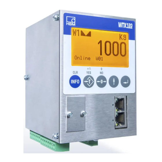
System description Fig. 4.1 WTX120 with integrated display and as black-box version with external display The WTX120 weighing terminal is a universal industrial weighing terminal for use in weighing or dispensing applications for example. The industrial weighing terminal features: S Standard Ethernet and USB ports... - Page 18 System description S EtherNet/IP S Profibus DP S Modbus TCP Additional options: S Analog output (mA; V/DC) S Up to 4 digital outputs and inputs WTX120 A4500-1.1 HBM: public...
-
Page 19: Installation
Installation Installation Overview of connections Fig. 5.1 WTX120 underside KL1: Load cell, 6-wire –EXC –Excitation –SEN –Sense –SIG –Signal +SIG +Signal +SEN +Sense +EXC +Excitation SHLD SHIELD WTX120 A4500-1.1 HBM: public... - Page 20 Supply voltage 12 V (–15%) to 30 V (+10%) DO 0 Dig.output 0 (Coarse/Fine active low) DO 1 Dig.output 1 (Fine/0-range) Feed to outputs 0-1 L1– Reference potential of outputs 0-1 Serial RS232 RS485 Not used WTX120 A4500-1.1 HBM: public...
-
Page 21: Installing The Device
S –10°C and +40°C, in applications subject to weights and measures legislation, S –10°C and +50°C, in applications not subject to weights and measures legislation. At 95% relative humidity (no condensation). Direct sunlight must be avoided. WTX120 A4500-1.1 HBM: public... -
Page 22: Connecting The Supply Voltage
The optional external display (1-WTX120-D) is suitable for panel-frame mounting. It may only be combined with WTX120 black-box variants. CAUTION On all WTX120 variants with integrated displays the DKU port is blocked with an additional notice label. The label must not be removed. Notice The shielding measures for connecting cables stipulated throughout this document must be followed. - Page 23 S The supply voltage is 12 V (–15%) to 30 V (+10%) at a maximum current consumption of 1.3 A. Only SELV voltages may be connected. S The supply voltage connection is protected against polarity reversal. Fig. 5.2 Underside of the WTX120 WTX120 A4500-1.1 HBM: public...
-
Page 24: Connection Of Analog Strain Gage Sensors
12 V (–15%) to 30 V (+10%) Connection of analog strain gage sensors The WTX120 permits the connection of analog strain gage sensors with the following specifications: S Maximum 8 strain gage load cells with 350 Ω each S Load cell impedance range 43 Ω ... 3321 Ω... - Page 25 Connection of a 6-wire analog load cell to the WTX120 Use a suitable terminal box, such as type VKK1-4 or VKK2-8 from HBM, to wire multiple load cells. To operate load cells without sense wires (4-wire mode), jumpers must be fitted on terminal KL1 between pins 1 and 2 and 5 and 6.
-
Page 26: Connecting Cables For Analog Load Receptors
The shield must in any case be installed in the immediate vicinity of the WTX120 (a maximum of 7 cm from the bottom edge of the WTX120's housing). S The load cells and load receptors, terminal boxes and weighing terminal must be integrated into the equipotential bonding system. -
Page 27: Connection Of Digital Inputs/Outputs (Di/Do)
+ and – signal connections must be swapped. Connection of digital inputs/outputs (DI/DO) The WTX120 has a maximum of 4 digital inputs/outputs. The following configuration levels are available independently of the primary PROFINET, EtherNet/IP, PROFIBUS DP and Modbus TCP interfaces:... - Page 28 Comments DI 0 Digital input 0 DI 1 Digital input 1 DI 2 Digital input 2 DI 3 Digital input 3 AO, I+ Analog output, mA AO, I- Analog output; mA DO 2 Digital output 2 WTX120 A4500-1.1 HBM: public...
- Page 29 S Shielded; shield on both sides S Flexible wires with wire end ferrules S Line impedance ≤125Ω/km Wire cross-section 0.2mm to max. 0.5mm ≤ 130 nF/km Line capacitance ≥ 250V Rated voltage Cable length max. 15m WTX120 A4500-1.1 HBM: public...
-
Page 30: Connection Of Analog Output (15-Bit)
The resolution of the analog output signal is 15 bits (32768 increments). The output signal of the analog output is active and potential-free. The analog output can be optionally balanced to 0/2-10V or 0/4-20mA in Service Mode group 'DAU15'. WTX120 A4500-1.1 HBM: public... -
Page 31: Connection Of Serial Ports
Interference on data transfer might result in delays or in the program stopping. To ensure optimal interference suppression of all injected frequencies, the shield should be applied on both sides. WTX120 A4500-1.1 HBM: public... -
Page 32: Connection Of The Profinet Device Variant
PROFINET network. This enables a star or linear topology to be constructed. The internal switch required for a linear topology is included in the WTX120. Information Cable length of a PROFINET segment without repeater (switch) max. 80 m WTX120 A4500-1.1 HBM: public... -
Page 33: Status Leds
Connection of the PROFINET device variant 5.8.1 Status LEDs Status Significance System error Green System started Tab. 5.5 D600 System failure (red/green) Status Significance No bus communication Green Successful bus communication Tab. 5.6 D601 Bus failure (red/green) WTX120 A4500-1.1 HBM: public... -
Page 34: Configuration Of Profinet Variants
The IP address of the PROFINET module is set on the PLC (e.g. S7, TIA) and not on the weighing terminal. To set the WTX120 parameters in the PROFINET variants, a GSDML file is required which you can download from www.hbm.com/de/6304/wtx120-indus... -
Page 35: Connection Of The Profibus Dp Device Variant
Installation Connection of the Profibus DP device variant Profibus DP Fig. 5.4 Connection of the Profibus DP device variant Connection Assignment Profibus-DP meaning B signal RTS signal Ground A signal Tab. 5.7 Terminal assignment U601 WTX120 A4500-1.1 HBM: public... -
Page 36: Configuration Of Profibus Dp
D601 System failure (red/green) 5.9.1 Configuration of Profibus DP In the Profibus device variants, the WTX120 works as a Profibus-DP slave, forming an I/O interface with up to 64 inputs and outputs, or as a data interface with up to 64 input words and 64 output words, and at a speed of 12 MBit/s. -
Page 37: Status Leds
Fig. 5.5 Connection to Ethernet/IP 5.10.1 Status LEDs Status Significance System error Green System started Tab. 5.9 D600 System failure (red/green) Status Significance No bus communication Green Successful bus communication Tab. 5.10 D601 Bus failure (red/green) WTX120 A4500-1.1 HBM: public... -
Page 38: Configuration Of Ethernet/Ip Variants
The IP address of the Ethernet/IP module is set on the PLC and not on the weighing terminal. In the EtherNet/IP variant, the WTX120 works as an Ethernet/IP adapter, forming an I/O interface with up to 64 input words and 64 output words. This device variant is suitable for transfer speeds up to 100 MBit/s. -
Page 39: Usb Port
5.12 USB port The USB port can be used to connect a storage device or an external keyboard. When using a USB keyboard, the following assignments apply: USB keyboard Weighing terminal Call Shift + F12 Service Mode WTX120 A4500-1.1 HBM: public... -
Page 40: Connection Of An External Display
All passwords can also be entered using the USB key board. 5.13 Connection of an external display Notice The optional external display (1-WTX120-D) is suitable for panel-frame mounting. It may only be combined with WTX120 black-box variants. The external display is connected on the underside, at the DKU port. -
Page 41: Operator Control/Settings
Operator control/settings Operator control/settings Display and control elements Fig. 6.1 WTX120 Display Display line Scale no. and weighing range Display: Scale is stopped in gross zero range (±0.2d) Display: Scale is moving Net weight with tared scale Unit Display of gross/net weight or guidance text and... - Page 42 Suffix a zero to a numeric entry. Suffix a blank to an alphanumeric entry. Back to previous program step Enter key Confirm entry, move on to next program step/menu Direct local input is possible using the display keys or a USB keyboard. WTX120 A4500-1.1 HBM: public...
-
Page 43: Example Of Entries Via Wtx120 Display Keys
Operator control/settings Example of entries via WTX120 display keys The following sections explain the operator control se quence based on the displayed user guidance texts and the corresponding entries. The displays are shown on the left-hand side. The following sections present examples of the input of alphanumeric characters and numbers. -
Page 44: Entering Whole Numbers
The CLR key is used to clear individual characters. 6.2.2 Entering whole numbers The following explains how to enter a sequence of digits. Here for example the sequence 123. Display Description of key function Terminal No.: Terminal No.: Clear all characters WTX120 A4500-1.1 HBM: public... - Page 45 2 Press to create a new digit position Terminal No.: Keep pressing until the desired digit appears, Terminal No.: e.g. 3 Apply value Terminal No.: Information The CLR key is used to clear individual characters. WTX120 A4500-1.1 HBM: public...
-
Page 46: Entering Numbers With Decimal Places
Keep pressing until the desired digit appears, e.g. 3 Press to move the digit one position to the left. Interval 1.230 Interval 1.234 Keep pressing until the desired digit appears, e.g. 4 Apply value Interval 1.234 WTX120 A4500-1.1 HBM: public... -
Page 47: Navigation Pilot
WTX120 V1.0 (Master = W1) hold + push to skip Switch from Master WTX120 to slaves WTX120 Remote Control (slaves = WA, WB, ...) hex / dez binär only available if WTX slaves are in the same < 3 seconds <... -
Page 48: Service Mode
Service Mode To access the Service Mode group select the following keys: Menu Function Switch to version notice Standard WTX120 V#.# Display the current firmware version number Call password entry within 3 seconds Enter the password Password Call Service Mode 1 Service Mode Service Mode is used to configure the weighing terminal. -
Page 49: Interface
NoAck acknowledgment →Protocol TTY selected Output character set: Com0: Codepage None None ISO8869 as per selected language DOS Codepage 'Western Europe' for older printers DOS Codepage 'Central Europe' DOS Codepage 'Russian' Star DOS Codepage Star printer WTX120 A4500-1.1 HBM: public... - Page 50 End character is included in checksum formation Com0: With end 7.1.2 Interface: Com1 (SIM) Menu Function/Secondary selection Interface Com1 (SIM1) Com1: Baud: 9600 Select the Baud rate of the Com1 interface: 300, 600, 1200, 2400, 4800, 9600, 19200, 38400, 57600, 115200 WTX120 A4500-1.1 HBM: public...
- Page 51 NoAck edgment →Protocol TTY selected Output character set: Com0: Codepage None None ISO8869 as per selected language DOS Codepage 'Western Europe' for older printers DOS Codepage 'Central Europe' DOS Codepage 'Russian' Star DOS Codepage Star printer WTX120 A4500-1.1 HBM: public...
- Page 52 →If start or end character entered and a checksum selected: Start character is included in checksum formation Com1: With start End character is included in checksum formation Com1: With end 7.1.3 Interface: Com2 (SIM) Menu Function/Secondary selection Interface Com2 (SIM2) WTX120 A4500-1.1 HBM: public...
-
Page 53: General
GMT can be selected. Automatic summer/winter time switching is imple mented according to the set zone. Notice: After changing the Time Zone the current Time must be set in the Supervisor Mode/ General group! WTX120 A4500-1.1 HBM: public... - Page 54 Required to comply with national approval re quirements. 2-character code according to ISO-3166-2, e.g.: Germany Great Britain Canada Netherlands Notice: Parameter protected by calibration switch S1. Select the decimal separator: Decimal char.: Dot (e.g. 1.00) Comma (e.g. 1,00) Comma WTX120 A4500-1.1 HBM: public...
- Page 55 For details on the continuous output Cont. Out: see chapter 12, page 146 Setting for continuous output: No continuous output HBM Remote HBM protocol Submenus see chapter 7.2.1 , page 54 Customized Freely defined output Submenus see chapter 7.2.1, page 54 WTX120 A4500-1.1 HBM: public...
- Page 56 (power-save function for battery operation). Serial No 1610410 7.2.1 Continuous Out → HBM Remote selected Protocol via Ethernet port (on underside of Cont. Out: device) SIM1 Protocol via serial interface Cont. Out port: 1900 TCP/IP port via which the external connection is made.
- Page 57 Service Mode Enter the number of updates of the continuous Cont: Out rate: output per second :G8 <See manual> Character string see also chapter 12.2 WTX120 A4500-1.1 HBM: public...
-
Page 58: Calibration
Calibration group. You will find the complete description of the calibration process in chapter 11, page 117. Menu Function Switch from Standard to version notice Standard WTX120 V#.# Display the current firmware version number Call password entry within 3 seconds Enter the password Password Call Service Mode... -
Page 59: Configuration
7.4.2 Config. Digital IO Menu Function/Secondary selection Config. Digital IO Digital inputs/outputs Modbus TCP To control external I/O modules via Ethernet, WTX120 works as the Modbus TCP master Not relevant REL/TRIO Not relevant Not relevant Not used None Notice: If the device variant has additional IOs, PIM must always be selected! →... - Page 60 0-10 V, 2-10 V, 0-20 mA, 4-20 mA → Gross or Net selected AOut 1: Scale Select the scale for gross/net weight output AOut 1:Calibration Fine adjustment of the minimum and maximum output signal: No fine adjustment Fine adjustment using a multimeter WTX120 A4500-1.1 HBM: public...
- Page 61 Calibrate full load value, e.g. =10V, adjust analog AOut 1: 10V = 4095 signal in increments Information The changed values are overwritten when the mode is changed! Information After resetting to factory defaults, the configuration for the Analog outputs menu must be performed. WTX120 A4500-1.1 HBM: public...
- Page 62 Service Mode 7.4.4 Configuration Fieldbus Information Modbus TCP is always provided via the Ethernet LAN port on the underside of the WTX120. Menu Function/Secondary selection Config. Fieldbus Select the connection for the fieldbus For variant with PROFINET: PROFINET, Modbus TCP, None...
- Page 63 The number of bits is vari Set multiple digital outputs able. Write multiple holding regis Multiple data words are written as from ters a data word address. The number of data words is variable. Write multiple output words WTX120 A4500-1.1 HBM: public...
- Page 64 The switch between the master WTX120 (W1) and the configured WTX120 slaves is made on the master by the (simultaneous) key combination Info and Enter. The display of the WTX120 W1 (master) indicates the active slave at the top left by WA=Slave1, WB=Slave2, WC=Slave3….
- Page 65 Service Mode Menu Function/Secondary selection End of list To first entry To previous entry Edit entry WTX120 A4500-1.1 HBM: public...
-
Page 66: Test
The digit keys can be used to set and reset the corresponding outputs (e.g. key 1 for output 1). The display above indicates the status: Input 0, 2, 3 = off Output 0 = on Input 1 = on Outputs 1-3 = off WTX120 A4500-1.1 HBM: public... - Page 67 RS485.4: Jumper from terminal 1 to 3 and from terminal 2 to 4 (Connect TxD+ to RxD+ and TxD– to RxD–). Notice: 2-wire RS485 and 20mA interfaces can not be tested in this way. Continue with next interface Com2: not ok WTX120 A4500-1.1 HBM: public...
-
Page 68: Reset
Com1: End char. 0 Com1: Parity None Com1: Checksum None General Language: German Tare mode: Gross/Net Date: DD.MM.YY Cont.out Off Time: HH:MM Light Off (Min.) 0 Decimal char.: Dot Power Off (Min.) 0 Approval signs: N WTX120 A4500-1.1 HBM: public... - Page 69 Scale/Config.Analog out or Config. Fieldbus. 7.6.2 Reset Approved Weight Menu Function/Secondary selection Service: Reset Reset approved weight Reset Approved Wgt No action Create new weight memory: Type Date+Id Date+Id With date and 4-digit ident number Cons.Id With 6-digit sequential no WTX120 A4500-1.1 HBM: public...
-
Page 70: Network
Mask: 255.255.0.0 Confirm and continue to next menu Gate: 144.84.77.65 Enter the IP address of the gateway, if required Confirm and continue to next menu DNS: Enter the DNS server Confirm and continue to next menu WTX120 A4500-1.1 HBM: public... - Page 71 (gateway, router or switch) cuts the connection if there is no communication for a lengthy period of time. If Auto PING is activated, an ICMP packet is sent every 60 seconds. WTX120 A4500-1.1 HBM: public...
- Page 72 Service Mode Menu Function/Secondary selection Terminal No.: Enter the terminal number for the network name. The network name is formed from the terminal type and number: e.g. WTX120_001, WTX120_123 WTX120 A4500-1.1 HBM: public...
-
Page 73: Backup
Restore Restore Content backed up When a backup is made, a file is generated by the WTX120 and written to the connected USB stick. This file can then be uploaded to one or more other WTX120 units. The following data items are saved/restored:... -
Page 74: Application
Switch to the Application group 1 Service Mode Call the Application group 2 Application General Setup In this menu group you can select the WTX120 application you need. These are Standard or Filler . Menu Function/Secondary selection 1 General Setup... - Page 75 Application Menu Function/Secondary selection Language To select the desired menu language in the Application group German German English English Information Notice: After changing the Application (Standard or Filler) the device must be restarted. WTX120 A4500-1.1 HBM: public...
-
Page 76: Limit Switches
Gross Toggle and select the mode Mode (LS1…LS4) Above Level For explanatory notes see 8.2.1 For explanatory notes see 8.2.2 Below Level Outside Band For explanatory notes see 8.2.3 Inside Band For explanatory notes see 8.2.4 WTX120 A4500-1.1 HBM: public... - Page 77 Enter the lower band value Lower band value (see chapters 8.2.3 and 8.2.4) Confirm and continue to next menu Band height Enter the band height (see chapters 8.2.3 and 8.2.4) 8.2.1 Mode: Above level Weight Level Hysteresis Time WTX120 A4500-1.1 HBM: public...
- Page 78 If the threshold is undershot, the relevant limit status is set. The limit is then likewise set on a preconfigured digital output (e.g. output 2 GW4). As soon as the level rises back above the threshold, the limit status is reset. WTX120 A4500-1.1 HBM: public...
- Page 79 The limit is then likewise set on a precon figured digital output (e.g. output 3 GW1). As soon as the weight is back in the band, the limit status is reset. WTX120 A4500-1.1 HBM: public...
- Page 80 The limit is then likewise set on a preconfigured digital output (e.g. output 3 GW1). As soon as the level is outside the band again, the limit status is reset. WTX120 A4500-1.1 HBM: public...
-
Page 81: Digital I/O
If the input is set (“1”), the applica Tare tion is tared Output 1…8 Deactivated Manual set/reset via ServiceMode/ Manual Reset (see chapter 7.6) Limit value 1 Limit value 2 Limit value 3 Limit value 4 WTX120 A4500-1.1 HBM: public... - Page 82 The following functional settings are available for configuration of the digital inputs: Deactivated Tare If the input is set (“1”), the applica tion is tared Stop the filling process instanta Stop neously. Start the filling process, provided all Start conditions are met. WTX120 A4500-1.1 HBM: public...
- Page 83 - has not been reached DL1/DL2 When the DL1/DL2 phase is acti vated, the output is activated dur ing DL2 Discharge During the discharge phase (weight and/or time controlled) the relevant discharge actuator is acti vated WTX120 A4500-1.1 HBM: public...
-
Page 84: Factory Defaults
For more information on the keys necessary to access this menu group, go to Navigation Pilot. Menu Function/Secondary selection Factory Defaults Load fact. Def. All settings are reset to their factory de faults. The device is then automatically restarted! No changes WTX120 A4500-1.1 HBM: public... -
Page 85: Mastermode
To access the Mastermode group select the following keys: Menu Function Switch from Standard to version notice Standard WTX120 V#.# Display the current firmware version number Call password entry within 3 seconds Enter the password Password Switch to the Application group... - Page 86 5 increments. The default setting is 0. Adapt the filtration level -5 to +5 Type Standard Here the characteristic of the digital filter can be set: Standard Critical Damped Butterworth Bessel WTX120 A4500-1.1 HBM: public...
- Page 87 1. This setting should only be increased if no set tled readout could be achieved with the Adapt mode Damping parameter and the Calibration mode Filter Size and Update-Rate parame ters. 1 to 8: Small to large working window WTX120 A4500-1.1 HBM: public...
-
Page 88: Supervisor Mode
To access the Supervisor Mode group select the following keys: Menu Function Switch from Standard to version notice Standard WTX120 V#.# Display the current firmware version number Call Supervisor Mode within 3 seconds Switch within the subgroups of Supervisor Mode Supervisor Mode Supervisor Mode is used to enter parameters during normal operation. -
Page 89: Products
Start Fine(s), Crs.mon.(s), Lockout crs(s), Fine mon.(s), Lock fine(s), Dos.delay1(s), Dos.delay2(s), Residual(s), Stabilizat.(s), Empt.time(s), Reset statistic, No.of dosing, Total weight, Mean value, Std.Dev. Information The Products group only appears when Application: Filler has been set in Service Mode/Application/General Setup/Application:Filler . WTX120 A4500-1.1 HBM: public... - Page 90 3 Save from USB Save data sets to the USB stick 10.2.2 <info> Presetting of what to do with the selected dosing parameter set. Setting options: Menu Function/Secondary selection Change the parameters <info> Edit Delete the parameter set Delete Print the parameter set Print WTX120 A4500-1.1 HBM: public...
- Page 91 Twelve characters are available to describe the product. 10.2.5 Dosing mode Menu Function/Secondary selection Dos.mode Upwards Upward dosing = a container is filled (see chapter 10.2.6) Downward dosing = material is Downwards taken from a filled container (silo, tank) (see chapter 10.2.6.1) WTX120 A4500-1.1 HBM: public...
- Page 92 Fig. 11.1 Upward dosing 10.2.6.1 Downward dosing In downward dosing, the decrease in weight of a container is measured while filling a (smaller) container. Fig. 11.2 Downward dosing WTX120 A4500-1.1 HBM: public...
- Page 93 Then the coarse flow phase starts. 10.2.8 Emptying Emptying mode can optionally be used to monitor the end of the filling process. During emptying, a digital output can be activated to control an emptying valve for example. Two variants are available: WTX120 A4500-1.1 HBM: public...
- Page 94 When emptying is complete, the end of the filling process is indicated by the Finished signal. WTX120 A4500-1.1 HBM: public...
- Page 95 If the previously measured actual value is below the lower tolerance limit, re- dosing is carried out. When optimization is active (parameter P1 > 0), the result of a re-dosing operation does not change the cut-off points. Re-dosing is carried out with a fine flow. WTX120 A4500-1.1 HBM: public...
- Page 96 < current measured value < lower tolerance limit When to re-dose? At the start of the dosing process Re-dose if the previously measured actual weight < lower tolerance limit When to re-dose? After checkweighing WTX120 A4500-1.1 HBM: public...
- Page 97 Dos.time Off/On the maximum dosing time (see also chapter 10.2.25, page 105) Alarm in case of deduction Container Off/On weighing and gross measured value < empty weight or gross measured value < target weight Min.start Off/On WTX120 A4500-1.1 HBM: public...
- Page 98 Coarse+Fine For explanatory notes see also chap Valve ter 10.2.12.1 Coarse+Fine2 For explanatory notes see also chap ter 10.2.12.2 Coarse/Fine For explanatory notes see also chap ter 10.2.12.3 Invers For explanatory notes see also chap ter 10.2.12.4 WTX120 A4500-1.1 HBM: public...
- Page 99 First fine flow phase Coarse flow cut- Time before coarse flow off point Start Fine flow cut- Time off point Fig. 11.4 Fill cycle with Coarse+Fine valve control with first fine flow phase activated (see also chapter 10.2.27) WTX120 A4500-1.1 HBM: public...
- Page 100 Coarse flow cut- Fine flow Time before coarse flow off point Start Fine flow cut- Time off point Fig. 11.6 Fill cycle with Coarse+Fine2 valve control with first fine flow phase activated (see also chapter 10.2.27) WTX120 A4500-1.1 HBM: public...
- Page 101 First fine flow phase Coarse flow cut- Fine flow cut- Time before coarse flow off point off point Fig. 11.8 Fill cycle with Coarse/Fine valve control with first fine flow phase activated (see also chapter 10.2.27) WTX120 A4500-1.1 HBM: public...
- Page 102 Fig. 11.10 Fill cycle with Invers valve control with first fine flow phase activated (see also chapter 10.2.27) 10.2.13 Empty weight When empty weight monitoring is active (see chapter 10.2.15 „Empty weight“), the filling process is aborted if the empty weight is exceeded at the start of fill ing. WTX120 A4500-1.1 HBM: public...
- Page 103 If it is, taring is carried out; otherwise no new taring is carried out (the old tare value is retained). WTX120 A4500-1.1 HBM: public...
- Page 104 (Coarse monitor). If the weight in crease rate is not exceeded, the fact is interpreted as a breakage of the con tainer being filled, and dosing is aborted. The coarse flow monitor is only active during the coarse flow phase. WTX120 A4500-1.1 HBM: public...
- Page 105 The minimum fine flow component specifies how close the coarse flow cut-off point can be taken to the fine flow cut-off point. This enables you to set the dif ference between the coarse and fine flows so that a fine flow results in every case. WTX120 A4500-1.1 HBM: public...
- Page 106 Tol.Error) is set. The status is cleared on the next startup. When you enter the target weight, the upper tolerance limit is automatically set to 100.2% of the target weight if no upper tolerance is set. WTX120 A4500-1.1 HBM: public...
- Page 107 Tare delay(s) You can use this time to block out disturbances, such as due to sack opening or mounting a container. Set the tare delay so that any such disturbances have been eliminated before taring begins. WTX120 A4500-1.1 HBM: public...
- Page 108 After starting or taring, and before the coarse flow, the fine flow signal is acti vated for the preset time. You can use this additional fine flow time before the coarse flow to prevent excessive foaming of the liquid being filled as a result of the coarse flow. WTX120 A4500-1.1 HBM: public...
- Page 109 You can prevent that with this setting. Experience shows that the lockout time should be about 10 % of the coarse flow dosing time. If you are using the coarse flow cut-off point monitor, the lockout time must be sufficient for mate rial to enter the container. WTX120 A4500-1.1 HBM: public...
- Page 110 If you enter the target weight the monitor is automatically deactivated. Information Select an increase in weight greater than the fluctuations caused by the mate rial escaping during the filling process. In the event of a breakage: WTX120 A4500-1.1 HBM: public...
- Page 111 You can prevent that with this set ting. Experience shows that the lockout time should be about 10 % of the fine flow dosing time. Weight Fine flow Lockout time Time Fig. 11.12 Fine flow lockout time WTX120 A4500-1.1 HBM: public...
- Page 112 Recording the residual flow is important for correct measurement of the actual weight in checkweighing, and so also for optimization where appropriate. The time to set depends on the dosing device and the settling time of the digital filter. WTX120 A4500-1.1 HBM: public...
- Page 113 With each dosing result the number of dosing operations is increased by 1. The Reset command clears the counter. The counter stops at 65.535 if it is not reset. The total weight, the mean value of the dosing results and the number of dosing operations are updated simultaneously. WTX120 A4500-1.1 HBM: public...
- Page 114 With each new dosing result the mean value of the dosing results is updated: Mean value of dosing results = total weight / number of dosing operations The total weight, the mean value of the dosing results and the number of dos ing operations are updated simultaneously. WTX120 A4500-1.1 HBM: public...
-
Page 115: Weight Storage
The stored values cannot be changed or deleted. 10.3.1 Displaying stored weight values Menu Function/Secondary selection Locate and display the weight parameters Weight Storage Search Date 99.99.99 Enter the date of the weight entry you are looking for Apply preset/changed date WTX120 A4500-1.1 HBM: public... - Page 116 (9999) is displayed. Enter the ident number of the weight entry you are looking for 10.3.2 Reset the “Approved Weight” The “Approved Weight” is reset in Service Mode in the Reset group (see chapter 7.6.2, page 67) WTX120 A4500-1.1 HBM: public...
-
Page 117: Logbook
Locate and display the logbook entries 3 Logbook Display an entry Display the last entry Display an entry Continue to older entry Display an entry Back to more recent entry, or back to Logbook menu level WTX120 A4500-1.1 HBM: public... -
Page 118: Software Id
It can be viewed, but not changed or deleted. Menu Function/Secondary selection Software ID ID: 15487782/V4.0.1 Display the identification number of the operating system and the version-number of the legal-for- trade software. Back to Software ID menu level WTX120 A4500-1.1 HBM: public... -
Page 119: Calibration
Calibration To access the Calibration group select the following keys: Menu Function Switch from Standard to version notice Standard WTX120 V#.# Display the current firmware version number Call password entry within 3 seconds Enter the password Password Call Service Mode... - Page 120 If 0.5 kg and 1 kg scale intervals are used, for example, 0.5 and 1.0 must be entered as the intervals. Additionally, the maximum resolution of the load cells being used (e.g. 3000d) must not be exceeded in any of the set ranges. WTX120 A4500-1.1 HBM: public...
-
Page 121: Multi-Interval
If 0.5 kg and 1 kg scale intervals are used, for exam ple, 0.5 and 1.0 must be entered as the intervals. Additionally, the maximum resolution of the load cells being used (e.g. 3000d) must not be exceeded in any of the set ranges. WTX120 A4500-1.1 HBM: public... - Page 122 When subsequently installing the scale at a location with differing gravita tional pull, all that is needed is to enter the geo value of the installation location. The scale does not have to be recalibrated in such a case. WTX120 A4500-1.1 HBM: public...
- Page 123 Unscrew the covering of the calibration switch on the front of the housing. You can use the now visible small calibration switch S1 to save the calibra tion data to the EEPROM locked safe against power outage: WTX120 A4500-1.1 HBM: public...
- Page 124 Switch down: (direction of terminals) calibration data can be changed Fig. 12.3 Calibration switch S1 WTX120 Information Position of switch S1 (under covering) For applications subject to weights and measures legislation, the covering and lid must be sealed by adhesive labels so that the position of the calibration switch can no longer be changed.
-
Page 125: Select Group 1-9
Finalize selection Save Parameters? Save the calibration data: Save data to EEPROM Discard all changes → If switch S1 up / saved Warning: Switch S1 not in calibration position, Error Calibr. Jumper parameters cannot be saved! WTX120 A4500-1.1 HBM: public... -
Page 126: Scale Parameters
Scale with one interval One Interval Scale with two intervals Two Intervals Scale with three intervals Three Intervals Scale with two intervals Two Intervals T+ with additive tare Three Intervals T+ Scale with three intervals with additive tare WTX120 A4500-1.1 HBM: public... - Page 127 Enter the maximum load of the lower range. Low Capacity 999999 Example:Low Capacity 3000 If the Low Capacity value is greater than High Capacity, the error message Entry Not Valid! is displayed. WTX120 A4500-1.1 HBM: public...
- Page 128 Capacity, the error message Entry Not Valid! is displayed. Enter the interval of the lowest range. Low Int. 999.9999 Example: Low Int. 1.0000 The error message Entry Not Valid! is dis played if you enter an invalid scale interval. WTX120 A4500-1.1 HBM: public...
- Page 129 Calibration Menu Function/Secondary selection Specify the unit of measurement symbol Unit Kilograms Grams Metric ton Pound Back to Select Group WTX120 A4500-1.1 HBM: public...
-
Page 130: Calibration
S Three 1000kg load cells with sensitivity of 1.99995mV/V, 2.00005mV/V and 2.00000mV/V respectively are used. S The maximum load is 1500kg; the interval 0.5kg S The weight of the empty tank is 600kg. Zero point Load point Fig. 12.4 Example of calibration of a tank weigher WTX120 A4500-1.1 HBM: public... - Page 131 Hinweis: The signal can be calculated in millivolts from the displayed mV/V value by multiplying it by the Excitation value (5V or 10V). Information The Clr key can be used to clear the value and enter a new one. WTX120 A4500-1.1 HBM: public...
- Page 132 Notice: The signal can be calculated in millivolts from the displayed mV/V value by multiplying it by the Excitation value (5V or 10V). Information The Clr key can be used to clear the value and enter a new one. WTX120 A4500-1.1 HBM: public...
- Page 133 The calibration values are saved when you exit the Select Group step, provided you answer the Save Parameters? prompt with Y Information To discard the calibration values, you must exit Setup without saving (Save Parameters No) before you can call another group. WTX120 A4500-1.1 HBM: public...
-
Page 134: Linearization
Press 3 times for group 3 Linearization Select Group 1-9 → Linearization points already present Display existing linearization points (1 to max. 6) Fixpoint 1: 999999 Delete existing linearization point Calibrate Fixpt? Lin.Signal 0.50000 Linearization signal is displayed WTX120 A4500-1.1 HBM: public... - Page 135 Do not enter linearization point; back to Select Group Enter the weight to be linearized Enter Fixpt.1 999999 Calibrate linearization point Calibrate Fixpt? Enter linearization value → With Calibrate Fixpt = Y Measure the linearization signal Linearization.. WTX120 A4500-1.1 HBM: public...
- Page 136 Enter a calculated linearization signal or import Lin.Signal1 0.50000 the values from another A/D converter Continue in New Fixpoint 2? step A new linearization point can be inserted between existing points. Then all the points are renumbered in ascending order. WTX120 A4500-1.1 HBM: public...
-
Page 137: Zero Adjust
Zero balance Adjusting... Measure the zero point Zero: 0.00 Display the new zero point in 10 times higher res olution (as a check). Zero(mV/V): 0.50000 Display the standardized signal - see Calculate Span Back to Select Group WTX120 A4500-1.1 HBM: public... -
Page 138: Adaptation
Here the filtration level of the digital filter is set. The following settings are possible: 1 to 20 Light to heavy filtering. With a very unstable scale display (such as in the case of live cattle weighers) heavy filtering is recommended. WTX120 A4500-1.1 HBM: public... - Page 139 Zero key, and in which automatic zeroing takes effect. Zero setting range (–) PbZero (%) - This sets the range below the power-up zero point in which the scale can be zeroed by the Zero key, and in which automatic zeroing takes effect. WTX120 A4500-1.1 HBM: public...
- Page 140 Must be set to Y(es) for applications in the USA, Canada and Australia! Hide weight display if gross weight values less Underload 20d? than -20d (below zero) For applications in accordance with OIML R76, Underload 20d must be set to Y WTX120 A4500-1.1 HBM: public...
- Page 141 If there is vibration around the scale, the proper ties of the digital filter can be optimized here. The update rate should be selected as far away as possible from the vibration frequency and from the multiple of the vibration frequency. WTX120 A4500-1.1 HBM: public...
-
Page 142: High Resolution
Menu Function/Secondary selection Press 6 times for group 6 High Resolution Select Group 1-9 Display the weight value in 10 times higher reso Weight: 9999999 lution (as a check of the scale) Back to Select Group WTX120 A4500-1.1 HBM: public... -
Page 143: Reset Parameters
Your calibration value Single/Dual/Triple Single 1 Scale Parameters Range Range One/Two/Three Intervals Interval Capacity 3000 Interval Unit Geo Value 2 Calibration Zero (mV/V) W1 0.00000 Load (mV/V) W1 2.00000 Zero (mV/V) W2 0.00000 Load (mV/V) W2 2.00000 WTX120 A4500-1.1 HBM: public... - Page 144 Auto Zero Range 0.5D Pushbutton Zero (+) Pushbutton Zero (–) Power Up Zero Overload Incline Switch NTEP Underload 20d With Taring Update Rate Zero (mV/V) 0.00000 8 Calculate Span LC-Capacity No.Of LCs mV/V Of LC1 2.00000 WTX120 A4500-1.1 HBM: public...
-
Page 145: Calculate Span
Continue to Zero(mV/V) step Measure the zero point of the scale Calibrating... Display the 10 times higher weight value Zero: 0.00 resolution (as a check) Zero(mV/V): 0.40000 Display the standardized signal (20% dead load = 20% signal) WTX120 A4500-1.1 HBM: public... - Page 146 Load(mV/V): 1.40000 Display the standardized signal for the maximum load (20% dead load + 50% net load) Information The Clr key can be used to clear the value and enter a new one. WTX120 A4500-1.1 HBM: public...
-
Page 147: W&M Info
Example: Value for overload display sup pression is set higher than 9d. Continue → Check the settings (allowable values in brackets) (0,5d) Motion Window Motion Counter (≥7) (0,5d) Autozero Range (≤4%) Pushbutton Range (max. 9d) Overload WTX120 A4500-1.1 HBM: public... -
Page 148: Continuous Output/Hbm Protocol (Cont.out)
Continuous output/HBM protocol (Cont.out) Continuous output/HBM protocol (Cont.out) To access the Cont. Out group select the following keys: Menu Function Switch from Standard to version notice Standard WTX120 V#.# Display the current firmware version number Call password entry within 3 seconds... - Page 149 Continuous output/HBM protocol (Cont.out) Example of remote display data set control 1. character: Start character always S 10.98 t 2. character: Status (blank) = scale stable 10980 kg D = scale in motion 3. - 12. character Weight 10 characters, in format of scale calibration 13.
-
Page 150: Wtx110 Remote Protocol
For WTX110 remote display, Remote Display mode must be set. Pressing of the Tare and Zero keys on the WTX110 (remote display) is re turned to the transmitter (the WTX120 weighing terminal), and corresponds to the same key press on the transmitter. -
Page 151: Customized Protocol
Continuous output/HBM protocol (Cont.out) 12.2 Customized protocol The data set is freely configurable. In the following table, x and y are place holders. If the condition is met, the character specified under x is displayed. If the condition is not met, the letter R specified under y is displayed instead. - Page 152 Continuous output/HBM protocol (Cont.out) String Sent Example zx:y Sends the character specified under x if the scale zA:N is not in the zero range, e.g.: N, otherwise the char acter specified undery. Sends the character specified under x if the scale...
- Page 153 Continuous output/HBM protocol (Cont.out) Example of a data set to control a remote display with stable/in motion and gross/net display. MM:S PN:G Unit Net weight, 8-digit if scale tared N (Net), otherwise G (Gross) in motion M (Motion), otherwise S (Stable)
-
Page 154: Plc Link
Word Byte no. N (High byte) N+1 (Low byte) Bit no. Signi- ficance The value range for Int16 (16-bit integer) is -32768 to 32765. The value range for UInt16 (16-bit unsigned integer) is 0 to 65535. WTX120 A4500-1.1 HBM: public... -
Page 155: Number Format Of 32-Bit Values
13.3 Input and output words The content of the data words is determined by the de fault settings. A distinction is made between “Standard” and “Filler“. The following tables provide an overview of the content of the existing data words. WTX120 A4500-1.1 HBM: public... -
Page 156: Standard" Application
PLC link 13.3.1 “Standard” application Input words WTX120 -> PLC Word content Data Contents type Net measured value Int32 Gross measured value Int32 DS461-Weight status General error Bits .2-3 Display status Scale in motion Calibration switch open Manual tare Bits .8-9... -
Page 157: Int16 Int16 Int16 Int16
Weight memory, month Int16 Weight memory, year Int16 Weight memory, Int16 seq. number Weight memory, gross Int16 Weight memory, net Int16 Output words WTX120 <- PLC Word content Data Contents type Control word Taring Gross/net Zeroing Data import Manual tare... -
Page 158: Int32 Uint8
Limit value 3 - Hysteresis/ Int32 Band height Limit value 4- Input UInt8 Limit value 4 - Mode UInt8 Limit value 4 - Switching Int32 level/Lower band limit Limit value 4 - Hysteresis/ Int32 Band height WTX120 A4500-1.1 HBM: public... -
Page 159: Filler" Application
PLC link 13.3.2 “Filler” application Input words WTX120 -> PLC Word content Data Contents type Net measured value Int32 Gross measured value Int32 DS461-Weight status General error Bits .2-3 Display status Scale in motion Calibration switch open Manual tare Bits .8-9... - Page 160 Output 4 Dosing status Coarse flow Fine flow Finished Re-dosing Emptying Flow error Alarm ADC - Overload/Underload Max. dosing time exceeded Legal-for-trade operation Tolerance error + Tolerance error - Status of digital input 1 General scale error WTX120 A4500-1.1 HBM: public...
- Page 161 Int32 sults Standard deviation Int32 Total weight Int32 Fine flow cut-off point Int32 Coarse flow cut-off point Int32 Actual dosing time UInt16 Actual coarse flow time UInt16 Actual fine flow time UInt16 Parameter set (product) UInt8 WTX120 A4500-1.1 HBM: public...
- Page 162 PLC link Output words WTX120 <- PLC Word content Data Contents type Control word Taring Gross/net Clear dosing results Abort dosing Start dosing Zeroing Data import Residual flow time UInt16 Filling weight Int32 Coarse flow cut-off point Int32 Fine flow cut-off point...
- Page 163 Word content Data Contents type Coarse fill flow monitoring UInt32 Fine fill flow monitoring UInt32 Fine fill flow monitoring time UInt16 Delay time after fine flow UInt8 Activation time after fine UInt8 flow Systematic difference UInt32 WTX120 A4500-1.1 HBM: public...
-
Page 164: Description Of Signal Exchange
(edge 4) and bit 14 is reset. The status of bit 15 is 1 if the command could be correctly executed, or 0 if an error occurred in executing it, e.g. Timeout. WTX120 A4500-1.1 HBM: public... -
Page 165: Measured Values
EW5 must be analyzed. EW0+ Net measured value EW2+ Gross measured value .4-6 Decimal places .7-8 Unit 0=kg, 1=g, 2=t, 3=lb Example: 1,000 g WTX120 A4500-1.1 HBM: public... -
Page 166: Status And Error Information
2: Above the maxi mum display value Scale in motion No standstill Calibration switch Calibration switch is open open Manual tare Manual tare 0=gross/1=net .8-9 range Multi-range scale: 0=range 1 1=range 2 2=range 3 WTX120 A4500-1.1 HBM: public... -
Page 167: Data Import
The last entry in the legal-for-trade memory is automati cally transferred into data words EW9 – EW14. Weight memory, day EW10 Weight memory, month EW11 Weight memory, year EW12 Weight memory, seq. number EW13 Weight memory, gross EW14 Weight memory, net WTX120 A4500-1.1 HBM: public... -
Page 168: Data Word Monitor
Function/Secondary selection Measured value display Call data word monitor - Input words/Output words Data word monitor Output words 0-63 Input words 0-63 Continue to next data word Back to previous data word Toggle “(Hex)adecimal” / “Binary” WTX120 A4500-1.1 HBM: public... -
Page 169: Transport, Maintenance And Cleaning
Calibration with legally verified weights at regular intervals is recommended. Operational checking can be carried out by way of the Service Mode menu. WTX120 A4500-1.1 HBM: public... -
Page 170: Cleaning
Do not spray the cleaner directly onto the de vice. When using cleaning agents containing acids, caustics or alcohol, the device must be cleaned off afterward with clear water. WTX120 A4500-1.1 HBM: public... -
Page 171: Replacing The Battery
Transport, maintenance and cleaning 14.4 Replacing the battery Battery compartment Fig. 15.1 Position of the battery compartment WARNING Cut the power to the terminal before opening it! WTX120 A4500-1.1 HBM: public... - Page 172 If the housing panel is opened the seal will be damaged! Notice Replace the batteries of legally verified calibrated sys tems every time a new calibration is carried out! WTX120 A4500-1.1 HBM: public...
- Page 173 Notice Insert a new battery within 30 seconds, otherwise the stored data will be lost! ► Cut the power to the device. ► Unscrew the battery cover panel and the verification jumper using a small screwdriver. WTX120 A4500-1.1 HBM: public...
- Page 174 ► Remove the old battery from the holder and insert a new battery. The positive terminal points upward! Notice: Make sure the polarity is correct, otherwise data entered will not be stored! The positive terminal points toward the left side of the terminal! WTX120 A4500-1.1 HBM: public...
- Page 175 ► Then refit the cover panel and secure it by the screws. The device is now ready to operate again. Important Please ensure that batteries are disposed of properly, in accordance with legal requirements. WTX120 A4500-1.1 HBM: public...
-
Page 176: Troubleshooting
S Exact wording of all error messages appearing on the display S Exact designation (type) of connected peripheral de vices linked to the problem (e.g. scale type, printer model, etc.). Please contact your local Service quoting these details. WTX120 A4500-1.1 HBM: public... - Page 177 Underload Range Out of Range Miss. Not installed Incl. Incline Sensor PUOvr Powerup Out of Range PUUdr Powerup Motion Invalid Not calibrated IOErr I/O Error Not I Not installed NotOk Not ok Other error message 32 WTX120 A4500-1.1 HBM: public...
-
Page 178: Error Messages
Scale overloaded Relieve load on scale Overload CPU not receiving data from Check external and internal weighing interface wiring Underload Gross weight values less Load scale than -20d (below zero) Set parameter Underload 20d to N=Off WTX120 A4500-1.1 HBM: public... - Page 179 (±2%, ±10%). Computer off or not ready Turn on computer or start re Transfer error ceive program Transfer cable defective or Check transfer cable and plug plug not attached In an emergency, disable data transfer in entries WTX120 A4500-1.1 HBM: public...
- Page 180 Service password Service password The Service password gives access to Service Mode. The default Service password is: (“3” ”2” “4” “Enter”) The Service password can be used as a universal local password. WTX120 A4500-1.1 HBM: public...
- Page 181 Navigation Pilot The relevant geo values can be determined using the geo values table see Tab. 18.2. Information For details on entering numbers via the WTX120 display see chapter 6.2.2 „Entering whole numbers“, page 6.2.2 Country Geo value France...
- Page 182 1625 1950 2275 2600 2925 3250 3575 Altitude above sea level in feet ° ° 1060 2130 3200 4260 5330 6400 7460 8530 9600 10660 1060 2130 3200 4260 5330 6400 7460 8530 9600 10660 11730 WTX120 A4500-1.1 HBM: public...
- Page 183 3250 3575 Altitude above sea level in feet ° ° 1060 2130 3200 4260 5330 6400 7460 8530 9600 10660 1060 2130 3200 4260 5330 6400 7460 8530 9600 10660 11730 Tab. 18.2 Geo values table WTX120 A4500-1.1 HBM: public...
- Page 184 Service password WTX120 A4500-1.1 HBM: public...
- Page 185 Operating Manual | Bedienungsanleitung Manuel d'emploi English Deutsch Français WTX120...
- Page 186 5.13 Anschluss externes Display ....... . WTX120 A4500-1.1 HBM: public...
- Page 187 Anzeige- und Bedienungselemente ......Beispiele für Eingaben über WTX120-Display-Tasten ..
- Page 188 ..........Mitlaufender Ausgang/HBM-Protokoll (Cont.out) .
- Page 189 ..........WTX120 A4500-1.1 HBM: public...
-
Page 190: Sicherheitshinweise
Montage sowie sorgfältige Bedienung voraus. Betriebsbedingungen S Schützen Sie das Gerät vor direktem Kontakt mit Wasser. S Schützen Sie das Gerät vor Feuchtigkeit und Witte rungseinflüssen wie beispielsweise Regen oder Schnee. Die Schutzklasse des Gerätes ist IP20 (DIN EN 60529). WTX120 A4500-1.1 HBM: public... - Page 191 Insbesondere sind jegliche Repara turen, Lötarbeiten an den Platinen (Austausch von Bauteilen) untersagt. Bei Austausch gesamter Bau gruppen sind nur Originalteile von HBM zu verwenden. S Das Gerät wird ab Werk mit fester Hard‐ und Soft warekonfiguration ausgeliefert. Änderungen sind nur im Rahmen der in der zugehörigen Dokumentation...
- Page 192 Ausbildung absolviert, die sie zur Reparatur der Automatisierungsanlagen befähigt. Außerdem haben sie die Berechtigung, Stromkreise und Geräte gemäß den Normen der Sicherheitstech nik in Betrieb zu nehmen, zu erden und zu kennzeich nen. WTX120 A4500-1.1 HBM: public...
- Page 193 Zuständen oder Datenverlust in der Auto matisierungseinrichtung führen. S Stellen Sie nach Einstellungen und Tätigkeiten, die mit Passworten geschützt sind, sicher, dass evtl. an geschlossene Steuerungen in einem sicheren Zu stand verbleiben, bis das Schaltverhalten des Gerätes geprüft ist. WTX120 A4500-1.1 HBM: public...
- Page 194 Das Wägeterminal darf nicht in explosionsgefährdeter Umgebung eingesetzt werden. Die Klassifizierung von explosionsgefährdeten Räumen (Einteilung in Zonen, Explosionsgruppen, Temperaturklassen, etc.) obliegt in jedem Fall dem Betreiber des Gerätes. Hierzu kann die Hilfe lokaler Gewerbeaufsichtsbehörden oder der WTX120 A4500-1.1 HBM: public...
- Page 195 S Alle Anlagenteile sind wirksam zu erden, um eine sta tische Aufladung zu vermeiden. Bewegliche Anlagen teile, z.B. fahrbare Waagen mit Kunststoffrädern, müssen z.B. mit Schleifbändern oder Erdklemmen wirksam geerdet und so gegen Aufladung geschützt werden. WTX120 A4500-1.1 HBM: public...
-
Page 196: Auf Dem Gerät Verwendete Kennzeichnungen
CE-Kennzeichnung Mit der CE‐Kennzeichnung garantiert der Hersteller, dass sein Produkt den Anforderungen der relevanten EG‐Richtlinien entspricht (die Konformitätserklärung finden Sie auf der Website von HBM (www.hbm.com) unter HBMdoc). Gesetzlich vorgeschriebene Kennzeichnung zur Entsorgung Nicht mehr gebrauchsfähige Altgeräte sind gemäß den nationalen und örtlichen Vorschriften für Umweltschutz... -
Page 197: Verwendete Kennzeichnungen
Produkt oder zur Handhabung des Produktes hin. Information Hervorhebung Kursive Schrift kennzeichnet Hervorhebungen im Siehe … Text und kennzeichnet Verweise auf Kapitel, Bilder oder externe Dokumente und Dateien. Menünamen und Menüeingaben sind in der Conso Service Mode las-Schrift gekennzeichnet WTX120 A4500-1.1 HBM: public... -
Page 198: Auf Dem Gerät Angebrachte Symbole
CE-Kennzeichnung Mit der CE‐Kennzeichnung garantiert der Hersteller, dass sein Produkt den Anforderungen der relevanten EG‐Richtlinien entspricht (die Konformitätserklärung finden Sie auf der Website von HBM (www.hbm.com) unter HBMdoc). Gesetzlich vorgeschriebene Kennzeichnung zur Entsorgung Nicht mehr gebrauchsfähige Altgeräte sind gemäß den nationalen und örtlichen Vorschriften für Umweltschutz... -
Page 199: Systembeschreibung
Systembeschreibung Systembeschreibung Abb. 4.1 WTX120 mit integriertem Display und als Blackbox-Version mit externem Display Das Wägeterminal WTX120 ist ein universell einsetzba res Industriewägeterminal zur Verwendung in z.B. Wäge- oder Dosierapplikationen. Das Industrie Wägeterminal verfügt über: S Standard Ethernet- und USB-Schnittstelle S Edelstahlgehäuse... - Page 200 Systembeschreibung S EtherNet/IP S Profibus DP S Modbus TCP Zusätzliche Optionen sind: S Analog Ausgang (mA; V/DC) S Bis zu 4 digitale Ausgänge und Eingänge WTX120 A4500-1.1 HBM: public...
-
Page 201: Installation
Installation Installation Übersicht der Anschlüsse Abb. 5.1 WTX120 Unterseite KL1: Load Cell, 6-Draht –EXC –Excitation –SEN –Sense –SIG –Signal +SIG +Signal +SEN +Sense +EXC +Excitation SHLD SHIELD WTX120 A4500-1.1 HBM: public... - Page 202 12 V (–15%) bis 30 V (+10%) +24V Versorgungsspannung 12 V (–15%) bis 30 V (+10%) DO 0 Dig.Ausg.0 (Grob/Fein active low) DO 1 Dig.Ausg.1 (Fein/0-Range) Speisung Ausgänge 0-1 L1– Bezugspotential Ausgänge 0-1 Serial RS232 RS485 Nicht verwendet WTX120 A4500-1.1 HBM: public...
-
Page 203: Aufstellen Des Gerätes
Aufstellen des Gerätes Die Betriebstemperatur darf zwischen: S –10°C und +40°C liegen, bei eichpflichtigen Anwendungen, S –10°C und +50°C liegen, bei nicht eichpflichtigen Anwendungen. Bei 95% relativer Luftfeuchte (ohne Kondensation). Di rekte Sonneneinstrahlung ist zu vermeiden. WTX120 A4500-1.1 HBM: public... -
Page 204: Anschluss Versorgungsspannung
Schaltschrank. Bei Installation mehrerer Module können diese direkt nebeneinander ohne seitlichen Ab stand auf die Hutschiene montiert werden. Hinweis Das optionale externe Display (1-WTX120-D) ist geeignet zum Schalttafel-Einbau. Es darf ausschließlich mit WTX120-Blackbox-Varianten kombiniert werden. VORSICHT Bei allen WTX120-Variaten mit integriertem Display ist der Anschluss DKU mit einem zusätzlichen Hinweis... - Page 205 8 Wägemodule angeschlossen werden. S Die Versorgungsspannung beträgt 12 V (–15%) bis 30 V (+10%) bei einer max. Stromaufnahme von 1,3 A. Es dürfen ausschließlich SELV-Spannungen angeschlossen werden. S Der Versorgungsspannungsanschluss ist verpolungs sicher. Abb. 5.2 Geräteunterseite des WTX120 WTX120 A4500-1.1 HBM: public...
-
Page 206: Anschluss Analoge Dms Sensoren
+24 V Versorgungsspannung 12 V (–15%) bis 30 V (+10%) Anschluss analoge DMS Sensoren Die WTX120 ermöglicht den Anschluss analoger DMS Sensoren folgender Spezifikationen: S Maximal 8 DMS-Wägezellen mit je 350 Ω S Wägezellenimpedanz-Bereich 43 Ω ... 3321 Ω S Eichfähige Auflösung 10.000e, intern 524.000d S Kleinstes zulässiges Eingangssignal für eichpflichtige... - Page 207 6-Leiter-Technik an die WTX120 Tipp Verwenden Sie für den Anschluss von mehreren Wäge zellen einen geeigneten Klemmenkasten, z.B. Typen VKK1-4 oder VKK2-8 von HBM, für die Verschaltung der Wägezellen. Für den Betrieb von Wägezellen ohne Sense-Leitungen (4-Leiter-Betrieb) müssen an der Klemme KL1 Kabel...
-
Page 208: Anschlusskabel Für Analoge Lastaufnehmer
Anwendungen an. Der Schirm ist in jedem Fall in unmittelbarer Nähe (maximal 7 cm von der Unter kante des WTX120-Gehäuses) der WTX120 zu installieren. S Wägezellen beziehungsweise Lastaufnehmer, Klemmkästen und Wägeterminal müssen in den Po... -
Page 209: Anschluss Digitale Ein-/Ausgänge (Di/Do)
Anschlüsse +Signal und –Signal getauscht werden. Anschluss Digitale Ein-/Ausgänge (DI/DO) Die WTX120 verfügt über maximal 4 digitale Ein-/Aus gänge. Die folgenden Ausbaustufen stehen unabhängig von den Primärschnittstellen PROFINET, EtherNet/IP, PROFIBUS DP, Modbus TCP zur Verfügung: S 2 fest installierte digitale Ausgänge in jeder Version S 2 x DO + 2 x DI, wenn Option Analog Ausgang vor... - Page 210 Stromaufnahme der Eingänge: max. 7mA bei 12-24VDC. DI/DO Bemerkungen DI 0 Digitaleingang 0 DI 1 Digitaleingang 1 DI 2 Digitaleingang 2 DI 3 Digitaleingang 3 AO, I+ Analog Ausgang, mA AO, I- Analog Ausgang; mA DO 2 Digitalausgang 2 WTX120 A4500-1.1 HBM: public...
- Page 211 Kabel für Signalleitungen müssen folgender Spezifikation entsprechen: S abgeschirmt, Schirm beidseitig aufgelegt S flexible Adern mit Aderendhülsen S Leitungswiderstand ≤ 125 Ω/km Leiterquerschnitt 0,2mm bis max. 0,5mm ≤ 130 nF/km Leitungskapazität ≥ 250V Nennspannung Kabellänge max. 15m WTX120 A4500-1.1 HBM: public...
-
Page 212: Anschluss Analogausgang (15-Bit)
Analog Ausgang genutzt werden. Die Auflösung des analogen Ausgangssignals beträgt 15 Bit (32768 Schritte). Das Ausgangssignal des Analog ausgangs ist aktiv und potentialfrei. Der Analogausgang ist im Service Mode Gruppe 'DAU15' wahlweise abgleichbar auf 0/2-10V oder 0/4-20mA. WTX120 A4500-1.1 HBM: public... -
Page 213: Anschluss Serielle Schnittstellen
Widerstand von maximal 500 Ohm haben. Spannungsausgang 0/2-10V: Die angeschlossene Last muss einen Widerstand von mindestens 500 Ohm haben. Anschluss serielle Schnittstellen Für die WTX120 stehen optional RS232 oder RS485 Schnittstellen zur Verfügung. KL3 Serial Anschluss RS232 RS485 4-Draht Tx A (Tx+) Tx B (Tx—) -
Page 214: Anschluss Profinet Gerätevariante
Für den Anschluss an ein PROFINET-Netzwerk stehen zwei RJ45-Buchsen an der Frontseite zur Verfügung. Damit kann eine Stern- oder eine Linientopologie aufge baut werden. Der für eine Linientechnologie notwendige interne Switch ist in der WTX120 enthalten. WTX120 A4500-1.1 HBM: public... -
Page 215: Status Leds
Installation Information Kabellänge eines PROFINET-Segments ohne Repeater (Switch) max. 80 m LEDs PROFINET Abb. 5.3 Anschluss PROFINET Gerätevariante 5.8.1 Status LEDs Zustand Bedeutung Systemfehler Grün System gestartet Tab. 5.5 D600 System Failure (rot/grün) WTX120 A4500-1.1 HBM: public... -
Page 216: Konfiguration Profinet Varianten
100 MBit/s geeignet. Die IP-Adresse des PROFINET-Moduls wird in der SPS- Steuerung (z. B. S7, TIA) und nicht im Wägeterminal ein gestellt. Zur Parametrierung der WTX120 in den PROFINET Vari anten wird eine GSDML-Datei benötigt, die Sie über www.hbm.com/de/6304/wtx120-industrielles-eichfae higes-waegeterminal/ in der Gerätekategorie WTX120... -
Page 217: Anschluss Profibus Dp Gerätevariante
Installation Anschluss Profibus DP Gerätevariante Profibus DP Abb. 5.4 Anschluss Profibus DP Gerätevariante Anschluss Belegung Bedeutung Profibus-DP B-Signal RTS-Signal Ground A-Signal Tab. 5.7 Klemmenbelegung U601 WTX120 A4500-1.1 HBM: public... -
Page 218: Konfiguration Profibus Dp
D601 System Failure (rot/grün) 5.9.1 Konfiguration Profibus DP Die WTX120 arbeitet in den Profibus Gerätevarianten als Profibus-DP-Slave, der eine I/O-Schnittstelle mit bis zu 64 Eingängen und Ausgängen bildet, oder als Daten- Schnittstelle mit bis zu 64 Eingangsworten und mit bis zu 64 Ausgangsworten und einer Geschwindigkeit von 12 MBit/s. -
Page 219: Status Leds
Installation LEDs EtherNet/IP Abb. 5.5 Anschluss Ethernet/IP 5.10.1 Status LEDs Zustand Bedeutung Systemfehler Grün System gestartet Tab. 5.9 D600 System Failure (rot/grün) Zustand Bedeutung Keine Buskommunikation Grün Erfolgreiche Buskommunikation Tab. 5.10 D601 Bus Failure (rot/grün) WTX120 A4500-1.1 HBM: public... -
Page 220: Konfiguration Ethernet/Ip Varianten
100 MBit/s. Die Bedeutung der einzelnen Datenworte ist von der Ap plikation abhängig und der entsprechenden Bedienungs anleitung zu entnehmen. Zur Parametrierung der WTX120 in den EtherNet/IP Va rianten wird eine EDS-Datei benötigt, die Sie über www.hbm.com/de/6304/wtx120-industrielles-eichfae higes-waegeterminal/ in der Gerätekategorie WTX120 herunterladen können. -
Page 221: Anschluss Usb
Installation 5.12 Anschluss USB Der USB Anschluss kann für einen Speicher oder für eine externe Tastatur verwendet werden. Bei Verwendung einer USB-Tastatur gelten folgende Zuord nungen: USB-Tastatur Wägeterminal Aufruf Shift + F12 Service Mode WTX120 A4500-1.1 HBM: public... -
Page 222: Anschluss Externes Display
Alle Passwörter lassen sich auch über die USB-Tastatur eingeben. 5.13 Anschluss externes Display Hinweis Das optionale externe Display (1-WTX120-D) ist geeignet zum Schalttafel-Einbau. Es darf ausschließlich mit WTX120-Blackbox-Varianten kombiniert werden. Das externe Display wird auf der Unterseite am An schluss DKU angeschlossen. Das Anschlusskabel ist im Lieferumfang der 1-WTX120-D enthalten. -
Page 223: Bedienung/Einstellungen
Bedienung/Einstellungen Bedienung/Einstellungen Anzeige- und Bedienungselemente Abb. 6.1 WTX120 Display Anzeige-Zeile Waagen-Nr. und Wägebereich Anzeige: Waage steht im Brutto-Nullbereich (±0,2d) Anzeige: Waage ist in Bewegung Nettogewicht bei tarierter Waage Einheit Anzeige Brutto-/Nettogewicht oder Führungstext und Eingabe WTX120 A4500-1.1 HBM: public... - Page 224 Anhängen einer Null an die nummerische Eingabe. Anhängen eines Leerfeldes an die alphanume rische Eingabe. Zurück zum vorhergehenden Programmschritt Enter-Taste Quittieren der Eingabe, weiter zu nächstem Pro grammschritt/Menü Die direkt Vor-Ort Eingabe ist über die Display-Tasten oder über eine USB-Tastatur möglich. WTX120 A4500-1.1 HBM: public...
-
Page 225: Beispiele Für Eingaben Über Wtx120-Display-Tasten
Die Eingabe schaltet um zwischen: =Großbuchstaben = Kleinbuchstaben =Ziffern und Sonderzeichen So oft drücken, bis gewünschter Buchstabe FTP pwd:E erscheint, z.B. E Drücken, um eine neue Ziffernstelle zu erzeugen FTP pwd:EA Festhalten, um Eingabemodus zu verändern. FTP pwd:E0 WTX120 A4500-1.1 HBM: public... -
Page 226: Eingabe Von Ganzen Zahlen
6.2.2 Eingabe von ganzen Zahlen Im folgenden wird erläutert wie eine Ziffernfolge eingege ben werden kann. Hier beispielsweise die Ziffernfolge 123. Anzeige im Display Taste Beschreibung der Tastenfunktion Terminal No.: Terminal No.: Alle Stellen löschen WTX120 A4500-1.1 HBM: public... - Page 227 So oft drücken, bis gewünschte Ziffer erscheint, z.B. 2 Terminal No.: Drücken, um eine neue Ziffernstelle zu erzeugen Terminal No.: So oft drücken, bis gewünschte Ziffer erscheint, z.B. 3 Wert übernehmen Terminal No.: Information Mit der CLR-Taste werden einzelne Stellen wieder gelöscht. WTX120 A4500-1.1 HBM: public...
-
Page 228: Eingabe Von Zahlen Mit Dezimalstellen
So oft drücken, bis gewünschte Ziffer erscheint, z.B. 3 Drücken, um die Ziffernstelle um eine Position Interval 1.230 nach links zu verschieben. Interval 1.234 So oft drücken, bis gewünschte Ziffer erscheint, z.B. 4 Wert übernehmen Interval 1.234 WTX120 A4500-1.1 HBM: public... -
Page 229: Navigation Pilot
WTX120 V1.0 (Master = W1) hold + push to skip Switch from Master WTX120 to slaves WTX120 Remote Control (slaves = WA, WB, ...) hex / dez binär only available if WTX slaves are in the same < 3 seconds <... -
Page 230: Service Mode
Für den Einstieg in die Gruppe Service Mode wählen Sie die folgenden Tasten: Menü Taste Funktion Standard Umschalten in die Versionsmeldung Anzeige der aktuellen Firmware Versionsnummer WTX120 V#.# Aufruf der Passwort-Eingabe innerhalb von 3 Sekunden Password Eingabe des Passworts 1 Service Mode Aufruf des Service Mode Der Service Mode dient der Konfiguration des Wägeterminals. -
Page 231: Schnittstellen Konfigurieren (Interface)
NoAck Gesicherte Prozedur ohne Quittung →Protokoll TTY gewählt Com0: Codepage None Zeichensatz der Ausgabe: None ISO8869 gemäß angewählter Sprache DOS Codepage 'Westeuropa' für ältere Drucker DOS Codepage 'Mitteleuropa' DOS Codepage 'Russisch' Star DOS Codepage Star Drucker WTX120 A4500-1.1 HBM: public... - Page 232 Com0: With end berücksichtigt 7.1.2 Einstellen der seriellen Schnittstelle (Interface: Com1 (SIM)) Menü Taste Funktion/Unterauswahl Interface Com1 (SIM1) Auswahl der Baudrate von Schnittstelle Com1: Com1: Baud: 9600 300, 600, 1200, 2400, 4800, 9600, 19200, 38400, 57600, 115200 WTX120 A4500-1.1 HBM: public...
- Page 233 NoAck Gesicherte Prozedur ohne Quittung →Protokoll TTY gewählt Com0: Codepage None Zeichensatz der Ausgabe: None ISO8869 gemäß angewählter Sprache DOS Codepage 'Westeuropa' für ältere Drucker DOS Codepage 'Mitteleuropa' DOS Codepage 'Russisch' Star DOS Codepage Star Drucker WTX120 A4500-1.1 HBM: public...
- Page 234 →wenn Start- oder Endezeichen eingegeben und einen Checksumme gewählt wurde: Startzeichen wird in Checksummenbildung Com1: With start berücksichtigt Endezeichen wird in Checksummenbildung Com1: With end berücksichtigt 7.1.3 Einstellen der seriellen Schnittstelle (Interface: Com2 (SIM)) Menü Taste Funktion/Unterauswahl Interface Com2 (SIM2) WTX120 A4500-1.1 HBM: public...
-
Page 235: Parameter Eingeben (General)
Apia. Mit Etc kann eine Zeit-Differenz zu GMT angewählt werden. Die automatische Sommerzeit-/Winterzeit- Umstellung erfolgt gemäß der eingestellten Zone. Hinweis: Nach einer Änderung der Time Zone muss die aktuelle Time in der Gruppe Supervisor Mode/General eingestellt werden! WTX120 A4500-1.1 HBM: public... - Page 236 Country Code Wird für entsprechende Zulassungs anforderungen des Landes benötigt. 2-stelliges Kurzzeichen nach ISO-3166-2, z.B.: Deutschland Großbritanien Kanada Niederlande Hinweis: Parameter durch Kalibrierschalter S1 Geschützt. Dezimal-Trennzeichen auswählen: Decimal char.: Punkt (z.B. 1.00) Komma (z.B. 1,00) Comma WTX120 A4500-1.1 HBM: public...
- Page 237 Detaillierte Erläuterungen zum mitlaufenden Aus Cont. Out: gang, siehe Kapitel 12, Seite 145 Einstellung für mitlaufenden Ausgang: Kein mitlaufender Ausgang HBM Remote HBM Protokoll Untermenüs siehe Kapitel 7.2.1, Seite 54 Customized Frei definierte Ausgabe Untermenüs siehe Kapitel 7.2.1, Seite 54 WTX120 A4500-1.1 HBM: public...
- Page 238 Gerät abgeschaltet wird (Strom sparfunktion für Batteriebetrieb) Serial No 1610410 7.2.1 Mitlaufender Ausgang (Continuous Out) → HBM Remote gewählt Cont. Out: Protokoll über Ethernet-Port (Unterseite Gerät) SIM1 Protokoll über serielle Schnittstelle TCP/IP-Port über dem die externe Verbindung Cont. Out port: 1900 aufgebaut wird.
- Page 239 Service Mode Eingabe der Anzahl der Aktualisierungen des Cont: Out rate: mitlaufenden Ausgangs pro Sekunde :G8 <See manual> Zeichenstring siehe auch Kapitel 12.2 WTX120 A4500-1.1 HBM: public...
-
Page 240: Waage Kalibrieren (Calibration)
Die vollständige Beschreibung der Kalibrierung finden Sie im Kapitel 11, Seite 115. Menü Taste Funktion Umschalten Standard in die Versionsmeldung Standard WTX120 V#.# Anzeige der aktuellen Firmware Versionsnummer Aufruf der Passwort-Eingabe innerhalb von 3 Sekunden Eingabe des Passworts Password... -
Page 241: Konfiguration (Configuration)
Digitale Ein-/Ausgänge konfigurieren (Config. Digital IO) Menü Taste Funktion/Unterauswahl Config. Digital IO Digitale Ein-/Ausgänge Modbus TCP zur Ansteuerung externer E/A-Mo dule über Ethernet, WTX120 arbei tet als Modbus TCP Master Nicht relevant REL/TRIO Nicht relevant Nicht relevant Nicht verwendet None Hinweis: Wenn Gerätevariante über zusätzliche... - Page 242 0-10 V, 2-10 V, 0-20 mA, 4-20 mA → Gross oder Net gewählt Auswahl der Waage für Ausgabe Brutto-/Nettoge AOut 1: Scale wicht Feineinstellung des minimalen und maximalen AOut 1:Calibration Ausgangssignals: Keine Feineinstellung Feineinstellung mit Hilfe eines Multimeters WTX120 A4500-1.1 HBM: public...
- Page 243 AOut 1: 10V = 4095 Voll-Lastwert kalibrieren, z.B. =10V, Analogsignal schrittweise verändern Information Die geänderten Werte werden überschrieben, wenn die Betriebsart geändert wird! Information Nach Rücksetzen auf Werkseinstellungen muss die Konfiguration für das Menü Analoge Ausgänge durchgeführt werden. WTX120 A4500-1.1 HBM: public...
- Page 244 Service Mode 7.4.4 Feldbus Schnittstelle konfigurieren (Configuration Fieldbus) Information Modbus TCP wird immer über die Ethernet Schnittstelle LAN auf der Unter seite der WTX120 zur Verfügung gestellt. Menü Taste Funktion/Unterauswahl Config. Fieldbus Anschluss für Feldbus auswählen Bei Variante mit PROFINET:...
- Page 245 7.4.5 Fernbedienung konfigurieren (Configuration Remote Ctrl) In der WTX120 mit Display sind die IP-Adressen der zusätzlichen, im gleichen Netzwerk befindlichen WTX ohne Display, einzutragen. Das Umschalten zwischen Master WTX120 (W1) und den kofigurierten WTX120 Slaves erfolgt am Master über die Tastenkombination Info und (gleichzeitig) Enter.
- Page 246 Service Mode Der Remote-Zugriff kann auch auf WTX120-Terminals mit integriertem Display erfolgen. In dieser Konstellation ist zu beachten, dass auf dem zugewiesenen Master-Display angezeigt wird, welcher Slave aktuell aktiv ist. Die sich im Netzwerk befindlichen und zugewiesenen WTX120-Slaves hin gegen zeigen immer W1 im Display (sofern eines vorhanden ist).
-
Page 247: Hardwaretest (Test)
Mit den Zifferntasten können die entsprechenden Ausgänge gesetzt und rückgesetzt werden (z.B. Taste 1 für Ausgang 1). Die obere Abbildung zeigt den Zustand: Eingang 0, 2, 3 = aus Ausgang 0 = an Eingang 1 = an Ausgänge 1-3 = aus WTX120 A4500-1.1 HBM: public... - Page 248 RS485.4: Brücke von Klemme 1 nach 3 und von Klemme 2 nach 4 (TxD+ mit RxD+ und TxD– mit RxD– verbinden). Hinweis: RS485 2-Draht und 20mA Schnittstellen können auf diese Weise nicht getestet werden. Weiter mit nächster Schnittstelle Com2: not ok WTX120 A4500-1.1 HBM: public...
-
Page 249: Parameter Zurücksetzen (Reset)
Com1: End char. 0 Com1: Parity None Com1: Checksum None General Language: German Tare mode: Gross/Net Date: DD.MM.YY Cont.out Off Time: HH:MM Light Off (Min.) 0 Decimal char.: Dot Power Off (Min.) 0 Approval signs: N WTX120 A4500-1.1 HBM: public... - Page 250 Eichfähiger Gewichtsspeicher löschen (Reset Approved Weight) Menü Taste Funktion/Unterauswahl Service: Reset Reset Approved Wgt Inhalte des eichfähigen Gewichtsspei chers löschen keine Aktion Neuen Gewichtsspeicher erstellen: Type Date+Id Date+Id Mit Datum und 4-stelliger Ident-Nr. Cons.Id Mit 6-stelliger laufender Nr. WTX120 A4500-1.1 HBM: public...
-
Page 251: Netzwerk (Network)
Bestätigen und weiter zum nächsten Menü Eingabe des DNS-Servers DNS: Bestätigen und weiter zum nächsten Menü Eingabe der IP-Adresse eines NTP-Servers für NTP: die Zeitsynchronisierung. Für die richtige Syn chronisierung ist die Wahl der Zeitzone erforder lich WTX120 A4500-1.1 HBM: public... - Page 252 Kommunikation stattfindet. Bei Aktivierung von Auto PING wird alle 60 Sekunden ein ICMP Paket gesendet. Terminal No.: Eingabe der Terminal-Nr. für den Netzwerk namen. Der Netzwerkname wird mit dem Terminaltyp und der Terminal-Nr. gebildet: z.B. WTX120_001, WTX120_123 WTX120 A4500-1.1 HBM: public...
-
Page 253: Sichern/Wiederherstellen (Backup)
Sichern Restore Wiederherstellen Gesicherte Inhalte Beim Backup wird eine Datei von der WTX120 erstellt und auf den angeschlos senen USB-Stick geschrieben. Diese Datei kann dann auf eine oder mehrere WTX120 geladen werden. Die folgenden Daten werden gesichert/wiederhergestellt: S Service Mode... -
Page 254: Application
Wechseln in die Gruppe Application 1 Service Mode Aufruf der Gruppe Application 2 Application Grundeinstellungen (General Setup) In dieser Menügruppe können Sie die gewünschte Anwendung der WTX120 auszuwählen. Diese sindStandard oder Filler (Füller). Menü Taste Funktion/Unterauswahl 1 General Setup Auswahl der gewünschten Applikation... - Page 255 Application Menü Taste Funktion/Unterauswahl Language Zur Auswahl der gewünschten Menüsprache im Bereich Application Deutsch German English Englisch Information Hinweis: Nach Änderung der Application (Standard bzw. Filler) muss das Gerät neu gestartet werden. WTX120 A4500-1.1 HBM: public...
-
Page 256: Grenzwerte (Limit Switches)
Quelle Grenzwertfunktion deaktiviert Nettosignal Bruttosignal Gros Wechseln zwischen und Auswahl des gewünsch Mode (LS1…LS4) ten Modi Above Level Erläuterungen siehe 8.2.1 Erläuterungen siehe 8.2.2 Below Level Outside Band Erläuterungen siehe 8.2.3 Inside Band Erläuterungen siehe 8.2.4 WTX120 A4500-1.1 HBM: public... - Page 257 Eingabe der unteren Bandgrenze (siehe Kapitel 8.2.3 und 8.2.4) Bestätigen und weiter zum nächsten Menü Eingabe der Bandhöhe Band height (siehe Kapitel 8.2.3 und 8.2.4) 8.2.1 Modus: Oberhalb Pegel (Above level) Gewicht Pegel Hysterese Zeit Ausgang WTX120 A4500-1.1 HBM: public...
- Page 258 Im Falle einer Unterschreitung wird der jeweilige Grenzwertstatus gesetzt. Bei einem vorher konfigurierten digitalen Ausgang (z.B. Ausgang 2 GW4) wird dieser dann ebenfalls gesetzt. Sobald der Pegel wieder überschritten wird, erfolgt ein Zurücksetzen des Grenzwertstatus. WTX120 A4500-1.1 HBM: public...
- Page 259 Band festgelegt. Außerhalb dieses Bands wird der jeweilige Grenzwertstatus gesetzt. Bei einem vorher konfigurierten digitalen Ausgang (z.B. Ausgang 3 GW1) wird dieser dann ebenfalls gesetzt. Sobald das Gewicht wieder innerhalb des Bands ist, erfolgt ein Zurücksetzen des Grenzwertstatus. WTX120 A4500-1.1 HBM: public...
- Page 260 Band festgelegt. Innerhalb dieses Bands wird der jeweilige Grenzwertstatus gesetzt. Bei einem vorher konfigurierten digitalen Ausgang (z.B. Ausgang 3 GW1) wird dieser dann ebenfalls gesetzt. Sobald der Pegel wieder außerhalb des Bandsist, erfolgt ein Zurücksetzen des Grenzwertstatus. WTX120 A4500-1.1 HBM: public...
-
Page 261: Konfiguration Digital Io (Digital I/O)
Taste Funktion/Unterauswahl Digital IO Input 1…8 Deaktiviert Wird der Eingang gesetzt („1“), wird Tare die Applikation tariert Deaktiviert Output 1…8 Manuell Manuelles Setzen/Rücksetzen über ServiceMode/Reset (siehe Kapitel 7.6) Grenzwert 1 Grenzwert 2 Grenzwert 3 Grenzwert 4 WTX120 A4500-1.1 HBM: public... - Page 262 Für die Konfiguration der digitalen Eingänge stehen folgende Funktions-Einstellungen zur Verfügung: Deaktiviert Tare Wird der Eingang gesetzt („1“), wird die Applikation tariert Stoppt den Füllprozess augenblick Stop lich. Start Startet den Füllprozess, sofern alle Bedingungen erfüllt sind. WTX120 A4500-1.1 HBM: public...
- Page 263 Tol. Error Meldet Toleranz+ wurde über- oder Toleranz- unterschritten DL1/DL2 Bei Aktivierung der DL1/DL2 Phase wird während DL2 der Aus gang aktiviert Discharge Während der Entleerphase (Gewichts- und/oder Zeitgesteuert) wird der entsprechende Aktor zum Entleeren aktiviert WTX120 A4500-1.1 HBM: public...
-
Page 264: Werkseinstellungen (Factory Defaults)
Für nähere Informationen zu den benötigten Tasten zum Einstieg in diese Menügruppe, gehen Sie zum Navigation Pilot. Menü Taste Funktion/Unterauswahl Factory Defaults Load fact. Def. Alle Einstellungen werden auf Werks einstellungen zurückgesetzt. Es folgt ein automatischer Neustart des Geräts! Keine Änderungen WTX120 A4500-1.1 HBM: public... -
Page 265: Mastermode
Für den Einstieg in die Gruppe Mastermode, wählen Sie die folgenden Tasten: Menü Taste Funktion Umschalten von Standard in die Versionsmel Standard dung WTX120 V#.# Anzeige der aktuellen Firmware Versionsnummer Aufruf der Passwort-Eingabe innerhalb von 3 Sekunden Eingabe des Passworts Password... - Page 266 Filter Size um bis zu 5 Schritte vermindert bzw. vergrößert werden. Die Standardeinstellung ist 0. -5 bis +5 Anpassung der Filterstärke Hier kann die Charakteristik des Digitalfilters ein Type Standard gestellt werden: Standard Critical Damped Butterworth Bessel WTX120 A4500-1.1 HBM: public...
- Page 267 Stufe 1. Diese Einstellung sollte nur vergrößert werden, wenn mit dem Adapt-Mode- Parameter Damping sowie den Kalibriermode- Parametern Filter Size und Update-Rate keine ruhige Anzeige erreicht werden konnte. 1 bis 8: Kleines bis großes Arbeitsfenster WTX120 A4500-1.1 HBM: public...
-
Page 268: Supervisor Mode
Menü Taste Funktion Standard Umschalten von Standard in die Versionsmel dung Anzeige der aktuellen Firmware Versionsnummer WTX120 V#.# Aufruf ders Supervisor Mode innerhalb von 3 Sekunden Wechseln innerhalb der Untergruppen des Supervisor Mode Supervisor Mode Der Supervisor Mode dient zur Eingabe von Parametern während des norma... -
Page 269: Produkte (Products)
Start Fine(s), Crs.mon.(s), Lockout crs(s), Fine mon.(s), Lock fine(s), Dos.delay1(s), Dos.delay2(s), Residual(s), Stabilizat.(s), Empt.time(s), Reset statistic, No.of dosing, Total weight, Mean value, Std.Dev. Information Die Gruppe Products im erscheint nur dann, wenn die Application: Filler im Service Mode/Application/General Setup/Application:Filler eingestellt wurde. WTX120 A4500-1.1 HBM: public... - Page 270 3 Save from USB Datensätze auf USB-Stick speichern 10.2.2 <info> Voreinstellung, was mit dem ausgewählten Dosier-Parametersatz passieren soll. Einstellungsmöglichkeiten: Menü Taste Funktion/Unterauswahl Ändern der Parameter <info> Edit Delete Löschen des Parametersatzes Print Ausdrucken des Parametersatzes WTX120 A4500-1.1 HBM: public...
- Page 271 Beschreibung des Produkts zur Verfügung. 10.2.5 Dosiermodus (Dos.mode) Menü Taste Funktion/Unterauswahl Dos.mode Upwards Aufwärtsdosierung = ein Behältnis wird gefüllt (siehe Kapitel 10.2.6) Abwärtsdosierung = aus einem Downwards gefüllten Behältnis (Silo, Tank) wird Material entnommen (siehe Kapi tel 10.2.6.1) WTX120 A4500-1.1 HBM: public...
- Page 272 Befüllens gewogen. In der Regel wird das Behältnis nach Abschluss der Fül lung mit dem Füllgut entnommen. Abb. 11.1 Aufwärtsdosierung 10.2.6.1 Abwärtsdosierung Bei der Abwärtsdosierung wird die Abnahme des Gewichts eines Vorratsbe hältnisses während der Befüllung eines (kleineren) Behältnisses gewogen. Abb. 11.2 Abwärtsdosierung WTX120 A4500-1.1 HBM: public...
- Page 273 Entleermodus (Emptying) Der Entleermodus kann optional genutzt werden, um das Ende des Füll vorgangs zu überwachen. Während der Entleerung kann ein digitaler Ausgang aktiviert werden, um beispielsweise ein Entleerventil zu steuern. Es stehen zwei Varianten zur Verfügung: WTX120 A4500-1.1 HBM: public...
- Page 274 Bruttowert unterhalb des Leergewicht liegt oder wenn die Entleerzeit überschritten wird, unabhängig davon, ob die Waage leer ist oder nicht. Nach dem Beenden des Entleerens wird das Ende des Füllvor gangs durch die Fertigmeldung signalisiert. WTX120 A4500-1.1 HBM: public...
- Page 275 10.2.10 Nachdosieren (Re-Dosing) Ist der zuvor gemessene Istwert unterhalb der unteren Toleranzgrenze, wird ein Nachdosieren ausgeführt. Das Ergebnis einer Nachdosierung verändert bei aktivierter Optimierung (Parameter P1 > 0) die Abschaltpunkte nicht. Das Nachdosieren erfolgt mit Feinstrom. WTX120 A4500-1.1 HBM: public...
- Page 276 Wann nachdosieren? Nach der Kontrollwägung Nachdosieren, wenn Feinstrom-Abschaltpunkt < aktueller Mess wert < untere Toleranzgrenze Wann nachdosieren? Beim Start des Dosiervorgangs ODER Nachdosieren, wenn das vorher ermittelte Ist-Gewicht < untere Toleranzgrenze Wann nachdosieren? Nach der Kontrollwägung WTX120 A4500-1.1 HBM: public...
- Page 277 Alarm bei Over-/Underflow von Bruttosignal, Nettosignal oder ADU-Wert Alarm bei Überschreitung der Dos.time Off/On maximalen Dosierzeit (siehe auch Kapitel 10.2.25, Seite 103) Alarm bei Abzugsverwiegung Container Off/On und Bruttomesswert< Leerge wicht oder Bruttomesswert < Füllgewicht Min.start Off/On WTX120 A4500-1.1 HBM: public...
- Page 278 Feinstrom. Es stehen 4 Modi zur Unterstützung verschiedener Ventil typen zur Verfügung: Menü Taste Funktion/Unterauswahl Coarse+Fine Erläuterungen siehe auch Kapi Valve tel 10.2.12.1 Coarse+Fine2 Erläuterungen siehe auch Kapi tel 10.2.12.2 Coarse/Fine Erläuterungen siehe auch Kapi tel 10.2.12.3 Invers Erläuterungen siehe auch Kapi tel 10.2.12.4 WTX120 A4500-1.1 HBM: public...
- Page 279 Feinstrom Zeit abschaltpunkt Abb. 11.3 Füllzyklus bei Ventilsteuerung Grob+Fein Grobstrom Erste Feinstromphase Grobstrom Feinstrom Zeit vor Grobstrom abschaltpunkt Start Feinstrom Zeit abschaltpunkt Abb. 11.4 Füllzyklus bei Ventilsteuerung Grob+Fein mit aktivierter erster Feinstromphase (siehe auch Kapitel 10.2.27) WTX120 A4500-1.1 HBM: public...
- Page 280 Zeit Feinstrom abschaltpunkt Abb. 11.5 Füllzyklus bei Ventilsteuerung Grob+Fein2 Grobstrom Erste Feinstromphase Grobstrom Feinstrom Zeit vor Grobstrom abschaltpunkt Start Feinstrom Zeit abschaltpunkt Abb. 11.6 Füllzyklus bei Ventilsteuerung ,Grob+Fein2' mit aktivierter erster Feinstromphase (siehe auch Kapitel 10.2.27) WTX120 A4500-1.1 HBM: public...
- Page 281 Abb. 11.7 Füllzyklus bei Ventilsteuerung Grob/Fein Grobstrom Erste Feinstromphase Grobstrom Feinstrom Zeit vor Grobstrom abschaltpunkt Start Erste Feinstromphase Grobstrom Feinstrom Zeit vor Grobstrom abschaltpunkt abschaltpunkt Abb. 11.8 Füllzyklus bei Ventilsteuerung ,Grob/Fein' mit aktivierter erster Feinstromphase (siehe auch Kapitel 10.2.27) WTX120 A4500-1.1 HBM: public...
- Page 282 Abb. 11.10 Füllzyklus bei Ventilsteuerung ,Invers' mit aktivierter erster Feinstromphase (siehe auch Kapitel 10.2.27) 10.2.13 Leergewicht Kontrolle (Empty weight) Bei aktivierter Leergewichtskontrolle (siehe Kapitel 10.2.15 „Leergewicht (Empty weight)“) wird der Füllvorgang abgebrochen, wenn das Leergewicht bei Start des Füllvorgangs überschritten wird. WTX120 A4500-1.1 HBM: public...
- Page 283 Enter) wird eine eventuell eingestellte Tarierverzögerung abgewartet und dann geprüft, ob das Gewicht unterhalb des angegebenen Werts für das Leerge wicht liegt. Wenn ja, wird tariert, ansonsten wird keine neue Tarierung durchge führt (der alte Tarawert bleibt erhalten). WTX120 A4500-1.1 HBM: public...
- Page 284 Sperrzeit Grobstrom wird nach jedem Zeitintervall (Überwachung Grobstrom) die Zunahme überprüft. Wird die Gewichtszunahme nicht über schritten, wird dies als Bruch des zu füllenden Behältnisses interpretiert und die Dosierung abgebrochen. Die Überwachung Grobstrom ist nur während der Grobstromphase aktiv. WTX120 A4500-1.1 HBM: public...
- Page 285 Minimaler Feinstromanteil (Min.Fine fl.) Der minimale Feinstromanteil legt fest, wie nahe der Grobstrom-Abschaltpunkt an den Feinstrom-Abschaltpunkt herangeführt werden kann. Damit können Sie den Abstand Grobstrom zu Feinstrom so einstellen, dass in jedem Fall ein Feinstrom erfolgt. WTX120 A4500-1.1 HBM: public...
- Page 286 Status „Toleranzgrenze überschritten“ und der entsprechend konfigurierte digitale Ausgang (Tol.+ oder Tol.Fehler) gesetzt. Der Status wird mit dem nächsten Start gelöscht. Bei der Eingabe des Füllgewichts wird die obere Toleranzgrenze automatisch auf 100,2% des Füllgewichts gesetzt, wenn keine obere Toleranz eingestellt ist. WTX120 A4500-1.1 HBM: public...
- Page 287 Fehler abgebrochen und die Ausgänge für Grob- und Feinstrom werden inaktiv gesetzt (siehe Kapitel 10.2.11 „Alarm (Alarm:Empty)“). 10.2.26 Tarierverzögerung (Tare delay(s)) Sie können diese Zeit dazu verwenden, um Störungen, z. B. durch Sackaufschuss oder Aufbringen eines Behältnisses, auszublenden. Stellen Sie WTX120 A4500-1.1 HBM: public...
- Page 288 Für die eingestellte Dauer wird nach dem Start oder dem Tarieren und vor dem Grobstrom das Feinstromsignal für die eingestellte Zeit aktiviert. Sie können diese zusätzliche Feinstromzeit vor dem Grobstrom verwenden, um ein zu starkes Aufschäumen der zu füllenden Flüssigkeit durch den Grobstrom zu vermeiden. WTX120 A4500-1.1 HBM: public...
- Page 289 Dies können Sie mit dieser Einstellung verhindern. Aus Erfahrung sollte die Sperrzeit bei etwa 10 % der Grobstromdosierzeit liegen. Falls Sie die Überwachung des Grobstrom-Abschaltpunkts verwenden, muss die Zeit so lang sein, dass innerhalb der Sperrzeit schon Material in das Behältnis gelangt. WTX120 A4500-1.1 HBM: public...
- Page 290 Behältnisses interpretiert und die Dosierung abgebrochen. Die Füllstromüber wachung des Feinstroms wird nach dem Erreichen des Feinstrom-Abschalt punkts deaktiviert. Bei der Eingabe des Füllgewichts wird die Überwachung automatisch deaktiviert. Information Wählen Sie die Gewichtszunahme größer als die materialbedingt auftretenden Schwankungen während des Füllvorgangs. WTX120 A4500-1.1 HBM: public...
- Page 291 Beim Abschalten des Grobstroms kann es zu Einschwingvorgängen kommen, die bereits zu einem Überschreiten des Feinstrom-Abschaltpunkts führen. Dies können Sie mit dieser Einstellung verhindern. Aus Erfahrung sollte die Sperrzeit bei etwa 10 % der Feinstromdosierzeit liegen. Gewicht Feinstrom Sperrzeit Zeit Abb. 11.12 Sperrzeit Feinstrom WTX120 A4500-1.1 HBM: public...
- Page 292 Bereits während der Dosierverzögerungszeit 1 wird das Statusbit Nachstrom gesetzt, siehe auch 16.2.32 Nachstromzeit. 10.2.34 Nachstromzeit (Residuals) Die Nachstromzeit startet nach Erreichen des Feinstrom-Abschaltpunkts. Sie dient der Erfassung des Nachstroms. Nach Ablauf dieser Verzögerungszeit wird die Kontrollwägung durchgeführt. WTX120 A4500-1.1 HBM: public...
- Page 293 Mit jedem Dosierergebnis wird die Anzahl Dosierungen um 1 erhöht. Der Rücksetzbefehl löscht den Zähler. Der Zähler bleibt bei 65.535 stehen, wenn er nicht zurückgesetzt wird. Das Summengewicht, der Mittelwert Dosierergeb nisse, sowie die Anzahl Dosierungen werden gleichzeitig aktualisiert. WTX120 A4500-1.1 HBM: public...
- Page 294 Dosierungen werden gleichzeitig aktualisiert. 10.2.39 Mittelwert Dosierergebnisse (Mean Valie) Mit jedem neuen Dosierergebnis wird der Mittelwert Dosierergebnisse aktualisiert: Mittelwert Dosierergebnisse = Summengewicht / Anzahl Dosierungen Das Summengewicht, der Mittelwert Dosierergebnisse, sowie die Anzahl Dosierungen werden gleichzeitig aktualisiert. WTX120 A4500-1.1 HBM: public...
-
Page 295: Gewichtsspeicher (Weight Storage)
Werte können weder verändert noch gelöscht werden. 10.3.1 Anzeige von gespeicherten Gewichtswerten Menü Taste Funktion/Unterauswahl Zur Suche und Anzeige der Gewichtsparameter Weight Storage Eingabe des Datums des zu suchenden Search Date 99.99.99 Gewichtseintrags Vorgegebenes bzw. geändertes Datum über nehmen WTX120 A4500-1.1 HBM: public... - Page 296 Anzahl der unter diesem Datum gespei cherten Einträge (9999). Eingabe der Ident-Nr. des zu suchenden Gewichtseintrags 10.3.2 Rücksetzen des „Eichfähigen Gewichtsspeichers“ Das Rücksetzen des „Eichfähigen Gewichtsspeichers“ erfolgt im Service Mode unter der Gruppe Reset (siehe Kapitel 7.6.2, Seite 66) WTX120 A4500-1.1 HBM: public...
-
Page 297: Logbuch (Logbook)
Taste Funktion/Unterauswahl 3 Logbook Zur Suche und Anzeige der Logbucheinträge Anzeige des letzten Eintrags Anzeige eines Eintrags Weiter zu älterem Eintrag Anzeige eines Eintrags Zurück zu jüngerem Eintrag, bzw. zurück auf Anzeige eines Eintrags Menüebene Logbook WTX120 A4500-1.1 HBM: public... -
Page 298: Software Id
Software einsehen. Information Es kann nur eingesehen, aber nicht verändert oder gelöscht werden. Menü Taste Funktion/Unterauswahl Software ID ID: 15487782/V4.0.1 Anzeige von Identifikations-Nummer des Betriebssystems und die Versions-Nummer der eichfähigen Software. Zurück auf Menüebene Software ID WTX120 A4500-1.1 HBM: public... -
Page 299: Kalibrierung (Calibration)
Tasten: Menü Taste Funktion Standard Umschalten von Standard in die Versionsmel dung Anzeige der aktuellen Firmware Versionsnummer WTX120 V#.# Aufruf der Passwort-Eingabe innerhalb von 3 Sekunden Password Eingabe des Passworts 1 Service Mode Aufruf des Service Mode 2 x drücken, um in die Auswahl der Gruppe... - Page 300 Bereiche gleich sein. Sollen z.B. die Teilungswerte 0.5 kg und 1 kg eingesetzt werden, so müssen 0.5 und 1.0 als Teilungswerte eingegeben werden. Außerdem darf die maximale Auflösung der verwendeten Wägezellen (z.B. 3000d) in keinem der eingestellten Bereiche überschritten werden. WTX120 A4500-1.1 HBM: public...
-
Page 301: Mehrteilungswaage (Multi-Interval)
Bereiche gleich sein. Sollen z.B. die Teilungswerte 0.5 kg und 1 kg eingesetzt werden, so müssen 0.5 und 1.0 als Teilungswerte eingegeben werden. Außerdem darf die maximale Auflösung der verwendeten Wägezellen (z.B. 3000d) in keinem der eingestellten Bereiche überschritten werden. WTX120 A4500-1.1 HBM: public... - Page 302 Waage bereits im Werk kalibriert wird. Bei anschließender Montage der Waage an einem Ort mit unterschiedlicher Erdanziehung muss lediglich der Geowert des Aufstellungsorts eingegeben werden. Die Waage muss in diesem Fall nicht erneut kalibriert werden. WTX120 A4500-1.1 HBM: public...
- Page 303 Etiketten versiegelt werden, so dass die Position des Kalibrierschalters nicht mehr verändert werden kann. ► Schrauben Sie die Abdeckung des Kalibrierschalters auf der Gehäusefront seite ab. Über den nun sichtbaren kleinen Kalibrierschalter S1 können die Kalibrierungsdaten spannungsausfallsicher im EEPROM gesichert werden: WTX120 A4500-1.1 HBM: public...
- Page 304 Kalibrierdaten gesichert, Änderungen nicht möglich Schalter unten: (Richtung Anschlüsse) Änderung der Kalibrierdaten möglich Abb. 12.3 Kalibrierschalter S1 WTX120 Information Position des S1-Schalters (unter der Abdeckung) Bei eichpflichtigen Anwendungen müssen Abdeckung und Deckel mit Klebe- Etiketten versiegelt werden, so dass die Position des Kalibrierschalters nicht mehr verändert werden kann.
-
Page 305: Gruppe Auswählen (Select Group 1-9)
Abspeichern der Kalibrierdaten: Save Paramaters? Abspeicher der Daten im EEPROM Alle Änderungen verwerfen → Wenn Schalter S1 in Stellung oben / gesichert Warnung: Schalter S1 nicht in Kalibrierposition, Error Calibr. Jumper Parameter können nicht abgespeichert werden! WTX120 A4500-1.1 HBM: public... -
Page 306: Scale Parameters
Waage mit zwei Teilungs Two Intervals werten Waage mit drei Teilungs Three Intervals werten Waage mit zwei Teilungs Two Intervals T+ werten mit Additiver Tara Three Intervals T+ Waage mit drei Teilungs werten mit Additiver Tara WTX120 A4500-1.1 HBM: public... - Page 307 Sie einen ungültigen Teilungs wert eingeben. Eingabe der Höchstlast des kleineren Bereichs. Low Capacity 999999 Beispiel: Low Capacity 3000 Ist der Wert Low Capacity größer als High Capacity, wird die Fehlermeldung Entry Not Valid! angezeigt. WTX120 A4500-1.1 HBM: public...
- Page 308 Ist der Wert Low Capacity größer als Mid Capacity, wird die Fehlermeldung Entry Not Valid! angezeigt. Low Int. 999.9999 Eingabe des Teilungswerts des kleinsten Bereichs. Beispiel: Low Int. 1.0000 Die Fehlermeldung Entry Not Valid! wird angezeigt, wenn Sie einen ungültigen Teilungs wert eingeben. WTX120 A4500-1.1 HBM: public...
- Page 309 Kalibrierung Menü Taste Funktion/Unterauswahl Angabe des Einheitenzeichens Unit Kilogramm Gramm Tonne Pound Zurück zu Select Group WTX120 A4500-1.1 HBM: public...
-
Page 310: Calibration
S 3 Wägezellen je 1000kg mit einer Empfindlichkeit von 1,99995mV/V, 2,00005mV/V und 2,00000mV/V werden benutzt. S Die Höchstlast beträgt 1500kg, die Teilung 0.5kg. S Das Gewicht des leeren Behälters beträgt 600kg. Nullpunkt Lastpunkt Abb. 12.4 Beispiel Kalibrierung einer Behälterwaage WTX120 A4500-1.1 HBM: public... - Page 311 Span. Hinweis: Aus dem angezeigten mV/V-Wert kann durch Multiplikation mit dem Wert Excitation (5V oder 10V) das Signal in Millivolt berechnet werden. Information Mit der Clr-Taste kann der Wert gelöscht und ein Neuer eingegeben werden. WTX120 A4500-1.1 HBM: public...
- Page 312 Calculate Span Hinweis: Aus dem angezeigten mV/V-Wert kann durch Multiplikation mit dem Wert Excitation (5V oder 10V) das Signal in Millivolt berechnet werden. Information Mit der Clr-Taste kann der Wert gelöscht und ein Neuer eingegeben werden. WTX120 A4500-1.1 HBM: public...
- Page 313 Frage Save Parameters? mit Y beant wortet wird Information Wenn die Werte der Kalibrierung verworfen werden sollen, muss der Setup ohne Abspeicherung verlassen werden (Save Parameters No), bevor eine andere Gruppe aufgerufen werden kann. WTX120 A4500-1.1 HBM: public...
-
Page 314: Linearization
3 x drücken für Gruppe 3 Linearization Select Group 1-9 → Linearisierungspunkte bereits vorhanden Fixpoint 1: 999999 Anzeige bereits vorhandener Linearisierungs punkte (1 bis max. 6) vorhandenen Linearisierungspunkt löschen Calibrate Fixpt? Linearisierungs-Signal wird angezeigt Lin.Signal 0.50000 WTX120 A4500-1.1 HBM: public... - Page 315 New Fixpoint 1? Linearisierungspunkt nicht eingeben, zurück zu Select Group Enter Fixpt.1 999999 Eingabe des Gewichts, das linearisiert werden soll Linearisierunspunkt kalibrieren Calibrate Fixpt? Linearisierungswert eingeben → Bei Calibrate Fixpt = Y Linearization.. Messung des Linearisierungs-Signals WTX120 A4500-1.1 HBM: public...
- Page 316 Lin.Signal1 0.50000 Signals oder die Übernahme von Werten eines anderen A/D-Wandlers Weiter im Schritt New Fixpoint 2? Ein neuer Linearisierungspunkt kann zwischen bestehenden Punkten eingefügt werden, danach werden alle Punkte in aufsteigender Reihenfolge neu numme riert. WTX120 A4500-1.1 HBM: public...
-
Page 317: Zero Adjust
Unload Scale Ein evt. vorhandenes Hilfsgestell oder andere Vorlasten entfernen. Nach Betätigen der Ein gabetaste wird der Nullpunkt gemessen. Nullabgleich Messung des Nullpunkts Adjusting... Anzeige des neuen Nullpunkts in 10-fach höhe Zero: 0.00 rer Auflösung (zur Kontrolle). WTX120 A4500-1.1 HBM: public... - Page 318 Kalibrierung Menü Taste Funktion/Unterauswahl Zero(mV/V): 0.50000 Anzeige des normierten Signals siehe Calculate Span Zurück nach Select Group WTX120 A4500-1.1 HBM: public...
-
Page 319: Adaptation
Beispiel: 20 = 0,4 sec Filter Size Filterstärke Hier wird die Stärke des digitalen Filters einge stellt. Folgende Einstellungen sind möglich: 1 bis 20 leichte bis starke Filterung. Bei sehr unruhiger Waagenanzeige (z.B. bei Lebendvieh-Waagen) wird eine starke Filterung empfohlen. WTX120 A4500-1.1 HBM: public... - Page 320 Nullziehen wirksam ist. Nullstellbereich (–) PbZero (%) - Hier wird der Bereich unterhalb des Einschalt- Nullpunkts eingestellt, in dem sich die Waage mittels der Nullstelltaste Nullstellen lässt, und in dem das automatische Nullziehen wirksam ist. WTX120 A4500-1.1 HBM: public...
- Page 321 Aus (Default) Muss für Anwendungen in USA, Kanada und Australien auf Y(es) stehen! Underload 20d? Ausblendung der Gewichtsanzeige bei Brutto- Gewichtswerten kleiner als -20d (unter Null) Für Anwendungen gemäß OIML R76 muss Underload 20d auf Y stehen WTX120 A4500-1.1 HBM: public...
- Page 322 Bei Vibrationen im Umfeld der Waage können hier die Eigenschaften des Digitalfilters optimiert werden. Die Update-Rate sollte so gewählt werden, dass sie möglichst weit von der Vibra tionsfrequenz und vom Vielfachen der Vibrations frequenz entfernt ist. WTX120 A4500-1.1 HBM: public...
-
Page 323: High Resolution
Mit dieser Menügruppe können Sie den Gewichtswert mit 10-fach höherer Auf lösung anzeigen. Menü Taste Funktion/Unterauswahl 6 x drücken für Gruppe 6 High Resolution Select Group 1-9 Anzeige des Gewichtswerts in 10-fach höherer Weight: 9999999 Gewichtswert-Auflösung (zur Kontrolle der Waage) Zurück nach Select Group WTX120 A4500-1.1 HBM: public... -
Page 324: Reset Parameters
Die folgende Tabelle zeigt Defaultwerte der Daten aus der Gruppe Calibration auf die, durch den Reset Parameter wieder zurückgesetzt wird. Gruppe Parameter Standard Ihre Kalibrierung wert 1 Scale Parameters Single/Dual/Triple Single Range Range One/Two/Three Intervals Interval Capacity 3000 Interval Unit WTX120 A4500-1.1 HBM: public... - Page 325 Auto Zero Range 0.5D Pushbutton Zero (+) Pushbutton Zero (–) Power Up Zero Overload Incline Switch NTEP Underload 20d With Taring Update Rate Zero (mV/V) 0.00000 8 Calculate Span LC-Capacity No.Of LCs mV/V Of LC1 2.00000 WTX120 A4500-1.1 HBM: public...
-
Page 326: Calculate Span
Nullabgleich der Waage: Calibrate Zero? Waage entlasten Nullpunkt kalibrieren weiter zum Schritt Zero(mV/V) Calibrating... Messung des Nullpunkts der Waage Zero: 0.00 Anzeige der 10-fach höheren Gewichtswert- Auflösung (zur Kontrolle) Anzeige des normierten Signals Zero(mV/V): 0.40000 (20% Totlast=20% Signal) WTX120 A4500-1.1 HBM: public... - Page 327 Weiter mit der nächsten Wägezelle, nach der letzten Wägezelle weiter im nächsten Schritt. Anzeige des normierten Signals für die Load(mV/V): 1.40000 Höchstlast (20% Totlast+50% Nettolast) Information Mit der Clr-Taste kann der Wert gelöscht und ein neuer Wert eingegeben werden. WTX120 A4500-1.1 HBM: public...
-
Page 328: W&M Info
Beispiel: Wert für Überlastausblendung ist eingestellt auf einen Wert größer 9d. Weiter → Überprüfung der Einstellungen (zulässige Werte in Klammern) Motion Window (0,5d) Motion Counter (≥7) Autozero Range (0,5d) (≤4%) Pushbutton Range (max. 9d) Overload WTX120 A4500-1.1 HBM: public... -
Page 329: Mitlaufender Ausgang/Hbm-Protokoll (Cont.out)
Mitlaufender Ausgang/HBM-Protokoll (Cont.out) Mitlaufender Ausgang/HBM-Protokoll (Cont.out) Für den Einstieg in die Gruppe Cont. Out (Mitlaufender Ausgang), wählen Sie die folgenden Tasten: Menü Taste Funktion Standard Umschalten von Standard in die Versionsmel dung Anzeige der aktuellen Firmware Versionsnummer WTX120 V#.# Aufruf der Passwort-Eingabe innerhalb von... - Page 330 Mitlaufender Ausgang/HBM-Protokoll (Cont.out) Beispiel Datensatzansteuerung Fernanzeige 1. Zeichen: Startzeichen immer S 10.98 t 2. Zeichen: Status (Leerzeichen) = Waage in Ruhe 10980 kg D = Waage in Bewegung 3. - 12. Zeichen Gewicht 10 Stellen, im Format der Waagen kalibrierung 13.
-
Page 331: Wtx110 Remote Protokoll
In der Fernanzeige WTX110 muss die Betriebsart Remote Display eingestellt sein. Die Betätigung der Tara- und Nulltaste an der WTX110 (Fernanzeige) wird an den Sender (das Wägeterminal WTX120) zurück übertragen und entspricht dem Tastendruck am Sender. 100.0 kgN 1. Zeichen: Status ~ = Waage in Bewegung °... -
Page 332: Customized Protokoll
Mitlaufender Ausgang/HBM-Protokoll (Cont.out) 12.2 Customized Protokoll Der Datensatz ist frei konfigurierbar. In der nachfolgenden Tabelle sind x und y Platzhalter. Ist die Bedingung erfüllt, wird das unter x angegeben Zeichen aus gegeben. Wenn die Bedingung nicht erfüllt ist, wird stattdessen der unter y angegebene Buchstabe R angezeigt. - Page 333 Mitlaufender Ausgang/HBM-Protokoll (Cont.out) String Gesendet Beispiel zx:y Sendet das unter x angegebene Zeichen, wenn zA:N die Waage nicht im Nullbereich ist, z.B.: N, ansons ten unter y angegebene Zeichen. Sendet das unter x angegebene Zeichen, wenn Px:y PT:N die Waage tariert ist, z.B.: T, ansonsten unter y angegebene Zeichen.
- Page 334 Mitlaufender Ausgang/HBM-Protokoll (Cont.out) Beispiel für einen Datensatz zur Ansteuerung einer Fernanzeige mit Ruhe / Bewegung und Brutto / Netto Anzeige. MM:S PN:G Einheit (Unit) Nettogewicht, 8-stellig wenn Waage tariert N (Net), sonst G (Gross) bei Bewegung M (Motion), sonst S (Stable)
-
Page 335: Sps-Kopplung
Zahlendarstellung als 16-stellige Dualzahlen oder als Bitmuster: Wort-Nr. n Byte-Nr. N (High-Byte) N+1 (Low-Byte) Bit-Nr. Bedeu tung Der Wertebereich für Int16 (16-Bit Integer) ist -32768 bis 32765. Der Wertebereich für UInt16 (16-Bit Unsigned Integer) ist 0 bis 65535. WTX120 A4500-1.1 HBM: public... -
Page 336: Zahlendarstellung Der 32-Bit-Werte
0 bis 4.294.967.295. 13.3 Ein- und Ausgangsworte Der Inhalt der Datenworte wird durch die Grundeinstel lung festgelegt, es wrid unterschieden zwischen “Stan dard” und “Füller“ (Filler). Die folgenden Tabellen geben einen Überblick über die Inhalte der vorhandenen Datenworte. WTX120 A4500-1.1 HBM: public... -
Page 337: Anwendung "Standard
SPS-Kopplung 13.3.1 Anwendung “Standard” Eingangsworte WTX120 -> SPS Wortinhalt Daten Inhalt Netto-Messwert Int32 Brutto-Messwert Int32 DS461-Gewichtsstatus Allgemeiner Fehler Bits .2-3 Anzeigestatus Waage in Bewegung Kalibrierschalter offen Handtara Netto Bits .8-9 Messbereich Genaue Null Innerhalb Nullstellbereich Messwertstatus .0-1 Anwendungsmodus .4-6 Nachkommastellen .7-8... - Page 338 Grenzwert 4 Gewichtsspeicher, Tag Int16 Gewichtsspeicher, Monat Int16 Gewichtsspeicher, Jahr Int16 Gewichtsspeicher, Lfd. Int16 Nummer Gewichtsspeicher, Brutto Int16 Gewichtsspeicher, Netto Int16 Ausgangsworte WTX120 <- SPS Wortinhalt Daten Inhalt Steuerwort Tarieren Brutto/Netto Nullstellen Datenübernahme Handtara Gewichtsspeicherung Handtarawert Int32 Grenzwert 1- Eingang...
- Page 339 UInt8 Grenzwert 3 - Schaltpegel/ Int32 Untere Bandgrenze Grenzwert 3 - Hysterese/ Int32 Bandhöhe Grenzwert 4- Eingang UInt8 Grenzwert 4 - Modus UInt8 Grenzwert 4 - Schaltpegel/ Int32 Untere Bandgrenze Grenzwert 4 - Hysterese/ Int32 Bandhöhe WTX120 A4500-1.1 HBM: public...
-
Page 340: Anwendung „Füller
SPS-Kopplung 13.3.2 Anwendung „Füller“ Eingangsworte WTX120 -> SPS Wortinhalt Daten Inhalt Netto-Messwert Int32 Brutto-Messwert Int32 DS461-Gewichtsstatus Allgemeiner Fehler Bits .2-3 Anzeigestatus Waage in Bewegung Kalibrierschalter offen Handtara Netto Bits .8-9 Messbereich Genaue Null Innerhalb Nullstellbereich Messwertstatus .0-1 Anwendungsmodus (0=Standard, 2= Füller) .4-6... - Page 341 Digitale Ausgänge Ausgang 1 Ausgang 2 Ausgang 3 Ausgang 4 Dosierstatus Grobstrom Feinstrom Fertig Nachdosieren Entleeren Durchflussfehler Alarm ADC - Überlast/Unterlast Max. Do sierzeitüberschreitung Eichfähiger Betrieb Toleranzfehler + Toleranzfehler - Status Digitaleingang 1 Allgemeiner Waagen Feh WTX120 A4500-1.1 HBM: public...
- Page 342 11 = Waagen-Fehler 255 = Inaktiv (Ser vicemode) Anzahl Dosierergebnisse UInt16 Dosierergebniss Int32 Mittelwert Dosierergeb Int32 nisse Standardabweichung Int32 Summengewicht Int32 Feinstromabschaltpunkt Int32 Grobstromabschaltpunkt Int32 Istzeit Dosieren UInt16 Istzeit Grobstrom UInt16 Istzeit Feinstrom UInt16 Parametersatz (Produkt) UInt8 WTX120 A4500-1.1 HBM: public...
- Page 343 SPS-Kopplung Ausgangsworte WTX120 <- SPS Wortinhalt Daten Inhalt Steuerwort Tarieren Brutto/Netto Dosierergebnisse löschen Abbruch Dosierung Start Dosierung Nullstellen Datenübernahme Nachstromzeit UInt16 Füllgewicht Int32 Grobstromabschaltpunkt Int32 Feinstromabschaltpunkt Int32 Minimaler Feinstrom Int32 Optimierung der Abschalt UInt8 punkte Maximale Dosierzeit UInt16 Start mit Feinstrom...
- Page 344 SPS-Kopplung Wortinhalt Daten Inhalt Füllstromüberwachung UInt32 Grob Füllstromüberwachung UInt32 Fein Füllstromüberwachungszeit UInt16 Fein Verzögerungszeit nach UInt8 Feinstrom Aktivierungszeit nach UInt8 Feinstrom Systematische Differenz UInt32 WTX120 A4500-1.1 HBM: public...
-
Page 345: Beschreibung Des Signalaustauschs
(erfolgreich ausgeführt) auf definierten Zustand gesetzt (Flanke 4) und das Bit 14 zurückgesetzt. Der Zustand von Bit 15 ist 1, wenn der Befehl korrekt abgearbeitet werden konnte, er ist 0, wenn bei der Ausführung ein Fehler aufgetreten ist, z.B. Timeout. WTX120 A4500-1.1 HBM: public... -
Page 346: Messwerte
Verfügung. Die Darstellung erfolgt als 32-Bit-Integer- Wert. Für die korrekte Wiedergabe der Messwerte ent sprechend der Kalibrierung müssen die Statusinforma tionen im Datenwort EW5 ausgewertet werden. EW0+ Netto-Messwert EW2+ Brutto-Messwert .4-6 Nachkommastellen .7-8 Einheit 0=kg, 1=g, 2=t, 3=lb Beispiel: 1,000 g WTX120 A4500-1.1 HBM: public... -
Page 347: Status- Und Fehlerinformationen
1: Unterhalb des minimalen Anzeige werts 2: Oberhalb des maximalen Anzeige werts Waage in Be Kein Stillstand wegung Kalibrierschalter Kalibrierschalter ist offen offen Handtara Handtara Netto 0=Brutto/1=Netto .8-9 Messbereich Mehrbereichs waage: 0=Bereich 1 1=Bereich 2 2=Bereich 3 WTX120 A4500-1.1 HBM: public... -
Page 348: Datenübernahme
Betriebsart „Standard“ verfügbar. Gewichtsspeicherung Der letzte Eintrag im eichfähigen Speicher wird automa tisch in den Datenworten EW9 – EW14 übertragen. Gewichtsspeicher, Tag EW10 Gewichtsspeicher, Monat EW11 Gewichtsspeicher, Jahr EW12 Gewichtsspeicher, Lfd. Nummer EW13 Gewichtsspeicher, Brutto EW14 Gewichtsspeicher, Netto WTX120 A4500-1.1 HBM: public... -
Page 349: Datenwort-Monitor
Betriebs möglich, den Inhalt der Eingangs- und Ausgangs-Datenworte zu kontrollieren. Der Monitor wird mit der Info-Taste aufgerufen. Menü Taste Funktion/Unterauswahl Aufruf Datenwort-Monitor Eingangsworte/Aus Messwertanzeige gangsworte Datenwort-Monitor Ausgangswort 0-63 Eingangsworte 0-63 Weiter zum nächsten Datenwort Zurück zum vorigen Datenwort Umschaltung „(Hexa-)dezimal“ / „Binär“ WTX120 A4500-1.1 HBM: public... -
Page 350: Transport, Wartung Und Reinigung
Eine Wartung von angeschlossenen Waagen-Unterwer ken ist in der Nutzung entsprechenden regelmäßigen ZeitKapitelen erforderlich. Diese müssen auf Fremdkör per, Metallsplitter, usw. kontrolliert werden, um eine Gewichtsbeeinträchtigung zu vermeiden. Eine Kalibrierung mit geeichten Gewichten in regelmäßigen Zeitabständen wird empfohlen. WTX120 A4500-1.1 HBM: public... -
Page 351: Reinigung
Tuch, das mit einem handelsüblichen Spül- oder Glas reinigungsmittel besprüht wurde. Den Reiniger nicht unmittelbar auf das Gerät sprühen. Bei Verwendung von Reinigungsmitteln, die Säuren, Laugen oder Alkohol enthalten, muss das Gerät anschließend mit klarem Wasser nachgereinigt werden. WTX120 A4500-1.1 HBM: public... -
Page 352: Batteriewechsel
Transport, Wartung und Reinigung 14.4 Batteriewechsel Batteriefach Abb. 15.1 Position des Batteriefachs WARNUNG Schalten Sie vor der Öffnung des Geräts das Terminal stromlos! WTX120 A4500-1.1 HBM: public... - Page 353 Batteriewechsel nicht mit dem Gehäuse in Berührung kommen! Hinweis Bei geeichten Systemen ist der Zugang zur Batterie mit einem Eichsiegel verklebt. Bei Öffnung der Gehäuseblende wird diese beschädigt! Hinweis Wechseln Sie bei geeichten Systemen die Batterie mit jeder Nacheichung! WTX120 A4500-1.1 HBM: public...
- Page 354 Setzen Sie innerhalb von 30 Sekunden eine neue Batte rie ein, sonst gehen die gespeicherten Daten verloren! ► Schalten Sie das Gerät stromlos. ► Schrauben Sie die Blende für Batterie und Eichjumper mit einem kleinen Schraubendreher ab. WTX120 A4500-1.1 HBM: public...
- Page 355 Entnehmen Sie die alte Batterie aus dem Halter und setzen eine neue Batterie ein. Der Plus-Pol zeigt nach oben! Hinweis: Achten Sie auf die richtige Polung, da sonst die eingegebenen Daten nicht gespeichert werden! Der Plus-Pol zeigt auf die linke Seite des Terminals! WTX120 A4500-1.1 HBM: public...
- Page 356 Plus-Pol zeigt auf die linke Seite des Terminals! Der Halter rastet im Batteriefach ein. ► Setzen Sie anschließend die Blende wieder auf und befestigen Sie diese mit den Schrauben. Das Gerät ist jetzt wieder betriebsbereit. WTX120 A4500-1.1 HBM: public...
- Page 357 Transport, Wartung und Reinigung Wichtig Bitte beachten Sie bei der Entsorgung verbrauchter Batterien die gesetzlichen Bestimmungen und führen Sie die Altteile einer geordneten Entsorgung zu. WTX120 A4500-1.1 HBM: public...
-
Page 358: Störungen
S Genauer Wortlaut aller Fehlermeldungen, die im Display angezeigt werden S Genaue Bezeichnung (Typ) der angeschlossenen Peripheriegeräte, die im Zusammenhang mit dem aufgetretenen Problem stehen (z.B. Waagen-Typ, Drucker-Modell, usw.). Mit diesen Angaben wenden Sie sich bitte an den zustän digen Service. WTX120 A4500-1.1 HBM: public... -
Page 359: Fehlerprotokoll Der Waage
Under Underload Range Out of Range Miss. Not installed Incl. Incline Sensor PUOvr Powerup Out of Range PUUdr Powerup Motion Invalid Not calibrated IOErr I/O Error Not I Not installed NotOk Not ok sonstige Fehlermeldung 32 WTX120 A4500-1.1 HBM: public... -
Page 360: Fehlermeldungen
Waage entlasten Überlast Waage in Überlast Waage entlasten Overload CPU empfängt keine Daten Externe und interne Verkabe vom Wägeinterface lung überprüfen Brutto-Gewichtswerte kleiner Waage belasten Unterlast Underload als -20d (unter Null) Parameter Underload 20d auf N=Aus stellen WTX120 A4500-1.1 HBM: public... - Page 361 Power-Up-Zero-Bereichs (±2%, ±10%) findet. EDV ausgeschaltet oder EDV einschalten oder Emp Fehler Übertragung nicht bereit fangs-Programm starten Übertragungskabel defekt Übertragungskabel und oder Stecker nicht aufge Stecker prüfen steckt Im Notfall Datenübertragung in Eingaben ausschalten WTX120 A4500-1.1 HBM: public...
-
Page 362: Service-Passwort
Service-Passwort Service-Passwort Mit dem Service-Passwort gelangt man in den Service Mode. Das voreingestellt Service-Passwort ist: (“3” ”2” “4” “Enter”) Das Service-Passwort kann als Universal-Vorort-Pass wort verwendet werden. WTX120 A4500-1.1 HBM: public... -
Page 363: Geowerte
Einstieg in diese Menügruppe, gehen Sie zum Navigation Pilot. Mit Hilfe der Geowerte-Tabelle (siehe Tab. 18.2) lassen sich die entsprechenden Geowerte ermitteln. Information Zur Eingabe von Zahlen über das WTX120-Display siehe Kapitel 6.2.2 „Eingabe von ganzen Zahlen“, Seite 6.2.2 Land Geowert Frankreich Finnland Belgien Dänemark... - Page 364 1300 1625 1950 2275 2600 2925 3250 3575 Höhe über Meeresspiegel in Fuß ° ° 1060 2130 3200 4260 5330 6400 7460 8530 9600 10660 1060 2130 3200 4260 5330 6400 7460 8530 9600 10660 11730 WTX120 A4500-1.1 HBM: public...
- Page 365 3575 Höhe über Meeresspiegel in Fuß ° ° 1060 2130 3200 4260 5330 6400 7460 8530 9600 10660 1060 2130 3200 4260 5330 6400 7460 8530 9600 10660 11730 Tab. 18.2 Tabelle zur Ermittlung der Geowerte WTX120 A4500-1.1 HBM: public...
- Page 366 Service-Passwort WTX120 A4500-1.1 HBM: public...
- Page 367 Operating Manual | Bedienungsanleitung | Manuel d'emploi English Deutsch Français WTX120...
- Page 368 ..........5.13 Raccordement de l'écran externe ......WTX120 A4500-1.1 HBM: public...
- Page 369 ......Exemples de saisies via les touches de l'écran WTX120 ..
- Page 370 ..........Sortie continue / Protocole HBM (Cont.out) .
- Page 371 Valeurs géographiques ........WTX120 A4500-1.1 HBM: public...
-
Page 372: Consignes De Sécurité
Conditions de fonctionnement S Protégez l'appareil contre tout contact direct avec de l'eau. S Protégez l'appareil de l'humidité et des intempéries, telles que la pluie ou la neige. Le degré de protection de l'appareil est IP20 (EN 60529). WTX120 A4500-1.1 HBM: public... - Page 373 à toute réparation ou soudure sur les circuits imprimés (remplacement de composants). En cas de remplacement de modules entiers, n'utiliser que des pièces d'origine HBM. S L’appareil est livré à la sortie d'usine avec une configuration matérielle et logicielle fixe. L’apport de modifications n’est autorisé...
- Page 374 à réparer les installations d'automatisation. Elles sont en outre autorisées à mettre en service, mettre à la terre et marquer des circuits électriques et appareils conformément aux normes de la technique de sécurité. WTX120 A4500-1.1 HBM: public...
- Page 375 S Après avoir effectué des réglages ou toute autre opération protégée par mots de passe, assurez-vous que les commandes éventuellement raccordées restent sûres jusqu'au contrôle du comportement de commutation de l'appareil. WTX120 A4500-1.1 HBM: public...
- Page 376 Le terminal de pesage ne doit pas être utilisé en atmosphère explosible. La classification des locaux présentant un risque d'explosion (répartition en zones, groupes d'appareils, classes de température, etc.) est WTX120 A4500-1.1 HBM: public...
- Page 377 à roues en plastique, doivent être reliées efficacement à la terre, par exemple via des bandes abrasives ou des bornes de mise à la terre, afin de les protéger de toute charge statique. WTX120 A4500-1.1 HBM: public...
-
Page 378: Marquages Utilisés Sur L'appareil
Le marquage CE permet au constructeur de garantir que son produit est conforme aux exigences des directives européennes correspondantes (la déclaration de conformité est disponible sur le site Internet de HBM (www.hbm.com) sous HBMdoc). Marquage d'élimination des déchets prescrit par la loi Les appareils usagés devenus inutilisables ne doivent... -
Page 379: Marquages Utilisés
Voir … et signalent des renvois à des chapitres, des illustrations ou des documents et fichiers externes. Les noms de menus et les saisies dans les menus Service Mode sont indiqués dans la police de caractères Consolas. WTX120 A4500-1.1 HBM: public... -
Page 380: Symboles Apposés Sur L'appareil
Le marquage CE permet au constructeur de garantir que son produit est conforme aux exigences des directives européennes correspondantes (la déclaration de conformité est disponible sur le site Internet de HBM (www.hbm.com) sous HBMdoc). Marquage d'élimination des déchets prescrit par la loi Les appareils usagés devenus inutilisables ne doivent... -
Page 381: Description Du Système
Fig. 4.1 WTX120 avec écran intégré et en version "boîte noire" avec écran externe Le terminal de pesage WTX120 est un terminal de pesage industriel universel à utiliser par exemple dans des applications de pesage ou de dosage. Le terminal de pesage industriel se compose des éléments suivants :... - Page 382 Description du système S Ethernet/IP S Profibus DP S Modbus TCP Options supplémentaires disponibles : S Sortie analogique (mA ; V/C.C.) S Jusqu’à 4 entrées et sorties numériques WTX120 A4500-1.1 HBM: public...
-
Page 383: Installation
Installation Installation Vue d’ensemble des connexions Fig. 5.1 Face inférieure du WTX120 KL1 : peson, 6 fils –EXC –Excitation (alimentation) –SEN –Sense (contre-réaction) –SIG –Signal +SIG +Signal +SEN +Sense (contre-réaction) +EXC +Excitation (alimentation) SHLD SHIELD (blindage) WTX120 A4500-1.1 HBM: public... - Page 384 12 V (–15 %) à 30 V (+10 %) DO 0 Sort. num. 0 (Gross./Fine active low) DO 1 Sort. num. 1 (Fine/Plage 0) Alimentation sorties 0-1 L1– Potentiel de référence sorties 0-1 Série RS232 RS485 Non utilisé WTX120 A4500-1.1 HBM: public...
-
Page 385: Installation De L'appareil
S –10 °C et +40 °C, pour les applications soumises à la vérification, S –10 °C et +50 °C, pour les applications non soumises à la vérification. Pour une humidité relative de l'air de 95 % (sans condensation). Éviter les rayons directs du soleil. WTX120 A4500-1.1 HBM: public... -
Page 386: Raccordement De La Tension D'alimentation
Il peut uniquement être combiné avec les variantes "boîte noire" du WTX120. ATTENTION Sur toutes les variantes du WTX120 avec écran intégré, la prise DKU est obturée par une étiquette supplémentaire. Ne pas retirer cette étiquette. Note Respecter impérativement toutes les mesures de... - Page 387 (–15 %) et 30 V (+10 %) pour une consommation de courant max. de 1,3 A. Seules de très basses tensions de sécurité peuvent être raccordées. S Le connecteur pour la tension d’alimentation est protégé contre les inversions de polarité. Fig. 5.2 Face inférieure du WTX120 WTX120 A4500-1.1 HBM: public...
-
Page 388: Raccordement De Capteurs À Jauges Analogiques
12 V (–15 %) à 30 V (+10 %) Raccordement de capteurs à jauges analogiques Le WTX120 permet de raccorder des capteurs à jauges analogiques présentant les spécifications suivantes : S Jusqu’à 8 pesons à jauges de 350 Ω chacun S Impédance des pesons comprise entre 43 Ω et 3321 Ω... - Page 389 Pour raccorder plusieurs pesons, utilisez un boîtier de raccordement approprié, par ex. de type VKK1-4 ou VKK2-8 de HBM, pour le branchement des pesons. Pour utiliser des pesons sans fils de contre-réaction (fonctionnement avec 4 fils), il est alors nécessaire de faire un pont au niveau du bornier KL1 entre les bornes 1 et 2, ainsi qu’entre les bornes 5 et 6.
-
Page 390: Câble De Raccordement Pour Récepteurs De Charge Analogiques
à la vérification. Le blindage doit toujours être installé à proximité immédiate du WTX120 (à 7 cm max. du bord inférieur du boîtier du WTX120). S Les pesons ou récepteurs de charge, les boîtiers de raccordement et le terminal de pesage doivent être reliés à... -
Page 391: Raccordement D'entrées/Sorties Numériques (Di/Do)
+Signal et –Signal. Raccordement d’entrées/sorties numériques (DI/DO) Le WTX120 dispose de 4 entrées/sorties numériques max. Les niveaux de configuration suivants sont disponibles, quelles que soient les interfaces primaires (PROFINET, Ethernet/IP, PROFIBUS DP, Modbus TCP) : S 2 sorties numériques fixes dans chaque version... - Page 392 Entrée numérique 0 DI 1 Non disp. Entrée numérique 1 DI 2 Non disp. Entrée numérique 2 DI 3 Non disp. Entrée numérique 3 Non disp. AO, I+ Sortie analogique ; mA Non disp. AO, I- Sortie analogique ; mA WTX120 A4500-1.1 HBM: public...
- Page 393 S Ils doivent être blindés, le blindage étant posé des deux côtés S Câbles flexibles avec embouts S Résistance de ligne ≤ 125 Ω/km Section 0,2 mm à 0,5 mm max. ≤ 130 nF/km Capacité ≥ 250 V Tension nominale Longueur de câble max. 15 m WTX120 A4500-1.1 HBM: public...
-
Page 394: Raccordement De La Sortie Analogique (15 Bits)
La résolution du signal de sortie analogique est de 15 bits (32768 incréments). Le signal de sortie de la sortie analogique est actif et sans potentiel. La sortie analogique peut être ajustée au choix à 0/2-10 V ou 0/4-20 mA dans le groupe 'DAU15’ du Service Mode. WTX120 A4500-1.1 HBM: public... -
Page 395: Raccordement D'interfaces Série
Sortie courant 0/4-20 mA : la charge raccordée peut avoir une résistance de 500 ohms max. Sortie tension 0/2-10 V : la charge raccordée doit avoir une résistance d’au moins 500 ohms. Raccordement d’interfaces série Le WTX120 peut disposer en option d’une interface RS232 ou RS485. KL3 série Borne RS232 RS485 4 fils... -
Page 396: Raccordement De La Variante Profinet
Deux prises RJ45 en façade permettent de raccorder l’appareil à un réseau PROFINET. Il est ainsi possible de réaliser une topologie en étoile ou linéaire. Le switch interne requis pour la topologie linéaire est intégré dans le WTX120. WTX120 A4500-1.1 HBM: public... -
Page 397: Del D'état
Longueur de câble d'un segment PROFINET sans répéteur (switch) : max. 80 m PROFINET Fig. 5.3 Raccordement de la variante PROFINET 5.8.1 DEL d’état État Signification Rouge Erreur système Vert Système démarré Tab. 5.5 D600 Erreur système (rouge/vert) WTX120 A4500-1.1 HBM: public... -
Page 398: Configuration Des Variantes Profinet
100 Mbits/s. L’adresse IP du module PROFINET se règle dans l’API (par ex. S7, TIA) et non pas dans le terminal de pesage. Pour paramétrer le WTX120 dans les variantes PROFINET, il faut un fichier GSDML que vous pouvez télécharger sous www.hbm.com/fr/6304/wtx120-terminal-... -
Page 399: Raccordement De La Variante Profibus Dp
Installation Raccordement de la variante Profibus DP Profibus DP Fig. 5.4 Raccordement de la variante Profibus DP Borne Affectation Signification Profibus DP Signal B Signal RTS Masse 5 V Signal A Tab. 5.7 Affectation des bornes U601 WTX120 A4500-1.1 HBM: public... -
Page 400: Configuration Profibus Dp
64 mots d’entrée et jusqu’à 64 mots de sortie et une vitesse de 12 Mbits/s. L’adresse Profibus se règle sous "Service Mode/Config. Fieldbus". Pour paramétrer les variantes Profibus DP du WTX120, il faut un fichier GSD que vous pouvez télécharger sous www.hbm.com/fr/6304/wtx120-terminal-de-pesage-indus triel-et-commercial/. -
Page 401: Del D'état
5.10.1 DEL d’état État Signification Rouge Erreur système Vert Système démarré Tab. 5.9 D600 Erreur système (rouge/vert) État Signification Rouge Pas de communication avec le bus Vert Communication avec le bus réussie Tab. 5.10 D601 Erreur bus (rouge/vert) WTX120 A4500-1.1 HBM: public... -
Page 402: Configuration Des Variantes Ethernet/Ip
L’adresse IP du module Ethernet/IP se règle dans l’API et non pas dans le terminal de pesage. Dans la variante Ethernet/IP, le WTX120 fonctionne comme adaptateur Ethernet/IP, formant une interface d’E/S avec jusqu’à 64 mots d’entrée et jusqu’à 64 mots de sortie. -
Page 403: Port Usb
Le port USB peut être utilisé pour raccorder une mémoire ou un clavier externe. Dans le cas d'un clavier USB, on applique les affectations suivantes : Clavier USB Terminal de pesage Appel Shift + F12 Service Mode WTX120 A4500-1.1 HBM: public... -
Page 404: Raccordement De L'écran Externe
Tous les mots de passe peuvent également être saisis au moyen du clavier USB. 5.13 Raccordement de l'écran externe Note L’écran externe disponible en option (1-WTX120-D) convient pour un montage en tableau de commande. Il peut uniquement être combiné avec les variantes "boîte noire" du WTX120. -
Page 405: Commande / Réglages
Commande / Réglages Commande / Réglages Éléments de contrôle et d'affichage Fig. 6.1 Écran WTX120 Ligne d'affichage N° de l'instrument de pesage et étendue de pesage Affichage : l'instrument de pesage se trouve dans la plage grossière du zéro (±0,2d) Affichage : l'instrument de pesage bouge Poids net lorsque l'instrument de pesage est taré... - Page 406 Retour à l'étape précédente du programme Touche Entrée Validation de l'entrée, passage à l'étape du programme / au menu suivant(e) La saisie directement sur place est possible en utilisant les touches de l'écran ou un clavier USB. WTX120 A4500-1.1 HBM: public...
-
Page 407: Exemples De Saisies Via Les Touches De L'écran Wtx120
Commande / Réglages Exemples de saisies via les touches de l'écran WTX120 Les paragraphes suivants expliquent la procédure d'utilisation en montrant les textes affichés à l'écran et les saisies correspondantes. Ce qui apparaît à l'écran est indiqué sur le côté gauche. - Page 408 Maintenir enfoncée pour changer de mode de FTP pwd:E1a saisie. Appuyer autant de fois que nécessaire jusqu'à ce FTP pwd:E1c que la lettre souhaitée apparaisse, par ex. c Reprendre la valeur FTP pwd:E1c Information La touche CLR permet d'effacer des digits particuliers. WTX120 A4500-1.1 HBM: public...
-
Page 409: Saisie De Nombres Entiers
Appuyer pour créer une nouvelle position Terminal No.: Appuyer autant de fois que nécessaire jusqu'à ce que le chiffre souhaité apparaisse, par ex. 3 Reprendre la valeur Terminal No.: Information La touche CLR permet d'effacer des digits particuliers. WTX120 A4500-1.1 HBM: public... -
Page 410: Saisie De Nombres Avec Décimales
Appuyer pour déplacer le chiffre d'une position Interval 1.230 vers la gauche. Interval 1.234 Appuyer autant de fois que nécessaire jusqu'à ce que le chiffre souhaité apparaisse, par ex. 4 Reprendre la valeur Interval 1.234 WTX120 A4500-1.1 HBM: public... -
Page 411: Navigation Pilot
WTX120 V1.0 (Master = W1) hold + push to skip Switch from Master WTX120 to slaves WTX120 Remote Control (slaves = WA, WB, ...) hex / dez binär only available if WTX slaves are in the same < 3 seconds <... -
Page 412: Service Mode
Pour accéder au groupe Service Mode, utilisez les touches suivantes : Menu Touche Fonction Passage à l'affichage de la version Standard WTX120 V#.# Affichage du numéro de version actuel du firmware Invitation à saisir le mot de passe dans les 3 secondes Password... -
Page 413: Configuration Des Interfaces (Interface)
None ISO8869 selon la langue choisie Page de code DOS 'Europe de l'Ouest' pour les imprimantes plus anciennes Page de code DOS 'Europe centrale' Page de code DOS 'Russe' Star Page de code DOS Imprimante Star WTX120 A4500-1.1 HBM: public... - Page 414 7.1.2 Réglage de l'interface série (Interface: Com1 (SIM)) Menu Touche Fonction / Sous-menu Interface Com1 (SIM1) Choix du débit binaire de l'interface Com1 : Com1: Baud: 9600 300, 600, 1200, 2400, 4800, 9600, 19200, 38400, 57600, 115200 WTX120 A4500-1.1 HBM: public...
- Page 415 None ISO8869 selon la langue choisie Page de code DOS 'Europe de l'Ouest' pour les imprimantes plus anciennes Page de code DOS 'Europe centrale' Page de code DOS 'Russe' Star Page de code DOS Imprimante Star WTX120 A4500-1.1 HBM: public...
- Page 416 Le caractère de fin est pris en compte dans la Com1: With end formation de la somme de contrôle 7.1.3 Réglage de l'interface série (Interface: Com2 (SIM)) Menu Touche Fonction / Sous-menu Interface Com2 (SIM2) WTX120 A4500-1.1 HBM: public...
-
Page 417: Saisie Des Paramètres (General)
Menu Touche Fonction / Sous-menu Language: German Choix de la langue German Allemand English Anglais Configuration du clavier USB : Keyboard: = américain = anglais Remarque : ne s'applique pas si Language: German WTX120 A4500-1.1 HBM: public... - Page 418 DD.MM.YYYY MM.DD.YYYY YYYY.MM.DD DD-MM-YYYY MM-DD-YYYY YYYY-MM-DD DD/MM/YYYY MM/DD/YYYY YYYY/MM/DD D = Jour, M = Mois, Y = Année Choisir le format de l'heure : Time: HH:MM HH:MM HH:MM:SS H = Heure, M = Minute, S = Seconde WTX120 A4500-1.1 HBM: public...
- Page 419 <25,45kg> / <10,00kg> / <15,45kg> ou <25,45kg> / 10,00kgPT / 15,45kgC Les valeurs de poids sont éditées confor mément à la directive européenne. Exemple : Brut/Tare/Net 25,45kg / 10,00kgT / 15,45kgN ou 25,45kg / 10,00kgPT / 15,45kgN WTX120 A4500-1.1 HBM: public...
- Page 420 Explications détaillées sur la sortie continue, Cont. Out: voir chapitre 12, page 146 Réglage pour la sortie continue : Pas de sortie continue HBM Remote Protocole HBM Sous-menus voir chapitre 7.2.1, page 55 Customized Sortie définie librement Sous-menus voir chapitre 7.2.1,...
- Page 421 Menu Touche Fonction / Sous-menu Serial No 1610410 7.2.1 Sortie continue (Continuous Out) → HBM Remote a été sélectionné Cont. Out: Protocole transmis via le port Ethernet (face inférieure de l'appareil) SIM1 Protocole transmis via l'interface série Cont. Out port: 1900 Port TCP/IP par lequel la connexion externe est établie.
-
Page 422: Étalonnage De L'instrument De Pesage (Calibration)
11, page 116. Menu Touche Fonction Passage de Standard à l'affichage de la Standard version WTX120 V#.# Affichage du numéro de version actuel du firmware Invitation à saisir le mot de passe dans les 3 secondes Saisie du mot de passe Password... -
Page 423: Configuration
Configuration des entrées/sorties numériques (Config. Digital IO) Menu Touche Fonction / Sous-menu Config. Digital IO Entrées/sorties numériques Modbus TCP Le WTX120 fonctionne alors comme maître Modbus TCP pour activer les modules d'E/S externes via Ethernet REL/TRIO Non applicable Non applicable Non applicable Non utilisé... - Page 424 → Gross ou Net a été sélectionné Choix de l'instrument de pesage pour la sortie AOut 1: Scale du poids brut/net Réglage fin du signal de sortie minimal et AOut 1:Calibration maximal : Pas de réglage fin Réglage fin à l'aide d'un multimètre WTX120 A4500-1.1 HBM: public...
- Page 425 = 10V ; changer progressivement le signal analogique Information Les valeurs modifiées seront écrasées lors du changement de mode de fonctionnement ! Information Après tout rétablissement des réglages d'usine, il est nécessaire de configurer le menu des sorties analogiques (Analog outputs). WTX120 A4500-1.1 HBM: public...
- Page 426 Service Mode 7.4.4 Configuration de l'interface bus de terrain (Configuration Fieldbus) Information Modbus TCP est toujours mis à disposition via la prise Ethernet LAN située sur la face inférieure du WTX120. Menu Touche Fonction / Sous-menu Config. Fieldbus Choix de la connexion pour le bus de terrain Pour la variante avec PROFINET :...
- Page 427 Write multiple holding Le système écrit plusieurs mots de registers données à partir d'une certaine adresse de mot. Le nombre de mots Écriture de plusieurs mots de données est variable. de sortie WTX120 A4500-1.1 HBM: public...
- Page 428 Configuration de la commande à distance (Configuration Remote Ctrl) Il faut entrer dans le WTX120 avec écran, les adresses IP des WTX supplé mentaires sans écran qui se trouvent dans le même réseau. La commutation entre le WTX120 maître (W1) et les WTX120 esclaves configurés se fait au niveau du maître via la combinaison de touches Info et...
- Page 429 Service Mode Menu Fonction / Sous-menu End of list Aller à la première entrée Aller à l'entrée précédente Éditer l'entrée WTX120 A4500-1.1 HBM: public...
-
Page 430: Test Matériel (Test)
(mettre à 1) et de réinitialiser (mettre à 0) les sorties correspondantes (par ex. la touche 1 pour la sortie 1). L'affichage au-dessus indique l'état : Entrées 0, 2, 3 = désactivées Sortie 0 = activée Entrée 1 = activée Sorties 1-3 = désact. WTX120 A4500-1.1 HBM: public... - Page 431 2 à la borne 4 (relier TxD+ à RxD+ et TxD– à RxD–). Remarque : il est impossible de tester le RS485 2 fils et les interfaces 20 mA de cette manière. Continuer avec l'interface suivante Com2: not ok WTX120 A4500-1.1 HBM: public...
-
Page 432: Réinitialisation Des Paramètres (Reset)
Com1: End char. 0 Com1: Parity None Com1: Checksum None General Language: German Tare mode: Gross/Net Date: DD.MM.YY Cont.out Off Time: HH:MM Light Off (Min.) 0 Decimal char.: Dot Power Off (Min.) 0 Approval signs: N WTX120 A4500-1.1 HBM: public... - Page 433 Suppression du contenu de la mémoire Reset Approved Wgt de poids apte à la vérification Aucune action Type Date+Id Créer une nouvelle mémoire de poids : Date+Id Avec date et numéro d'identification à 4 chiffres Cons.Id Avec numéro séquentiel à 6 chiffres WTX120 A4500-1.1 HBM: public...
-
Page 434: Réseau (Network)
Saisie du serveur DNS Validation et passage au menu suivant NTP: Saisie de l'adresse IP d'un serveur NTP pour la synchronisation du temps. Pour avoir une synchronisation correcte, il est nécessaire de choisir le fuseau horaire WTX120 A4500-1.1 HBM: public... - Page 435 ICMP est alors envoyé toutes les 60 secondes. Saisie du numéro de terminal pour le nom du Terminal No.: réseau. Le nom du réseau est formé avec le type de terminal et le numéro de terminal, par ex. WTX120_001, WTX120_123 WTX120 A4500-1.1 HBM: public...
-
Page 436: Sauvegarde/Restauration (Backup)
Restore Restauration Contenus sauvegardés Lors de la sauvegarde, le WTX120 crée un fichier et l'écrit sur la clé USB raccordée. Ce fichier peut alors être chargé sur un ou plusieurs WTX120. La sauvegarde/restauration porte sur les données suivantes : S Service Mode S Application Filler/Standard Contenus non sauvegardés... -
Page 437: Application
1 Service Mode Appel du groupe Application 2 Application Réglages de base (General Setup) Ce groupe de menus permet de sélectionner l'application souhaitée du WTX120. Cela peut être Standard ou Filler (remplisseur). Menu Touche Fonction / Sous-menu 1 General Setup Sélection de l'application souhaitée... - Page 438 Touche Fonction / Sous-menu Language Permet de sélectionner la langue des menus souhaitée dans le groupe Application Allemand German English Anglais Information Remarque : après toute modification dans Application (Standard ou Filler), il est nécessaire de redémarrer l'appareil. WTX120 A4500-1.1 HBM: public...
-
Page 439: Bascules À Seuil (Limit Switches)
Signal net Gros Signal brut Commutation entre les modes et sélection du Mode (LS1…LS4) mode souhaité Above Level Explications, voir 8.2.1 Below Level Explications, voir 8.2.2 Explications, voir 8.2.3 Outside Band Inside Band Explications, voir 8.2.4 WTX120 A4500-1.1 HBM: public... - Page 440 (voir chapitres 8.2.3 et 8.2.4) Validation et passage au menu suivant Saisie de la hauteur de bande Band height (voir chapitres 8.2.3 et 8.2.4) 8.2.1 Mode : Au-dessus du seuil (Above level) Poids Seuil Hystérésis Temps Sortie WTX120 A4500-1.1 HBM: public...
- Page 441 (mis à 1). Si une sortie numérique a été configurée au préalable (par ex. Output 2 GW4), celle- ci est également activée. Dès que la valeur repasse au-dessus du seuil, l'état du seuil est remis à zéro. WTX120 A4500-1.1 HBM: public...
- Page 442 Si une sortie numérique a été configurée au préalable (par ex. Output 3 GW1), celle-ci est également activée. Dès que le poids revient au sein de la bande, l'état des seuils est remis à zéro. WTX120 A4500-1.1 HBM: public...
- Page 443 été configurée au préalable (par ex. Output 3 GW1), celle-ci est également activée. Dès que le niveau se trouve de nouveau en dehors de la bande, l'état des seuils est remis à zéro. WTX120 A4500-1.1 HBM: public...
-
Page 444: Configuration Des E/S Numériques (Digital I/O)
Si l'entrée est mise à 1, l'ap Tare plication va être tarée Désactivée Output 1…8 Manual Activation/Désactivation ma nuelle via ServiceMode/Reset (voir chapitre 7.6) Valeur limite 1 Valeur limite 2 Valeur limite 3 Valeur limite 4 WTX120 A4500-1.1 HBM: public... - Page 445 Pour configurer les entrées numériques, vous disposez des fonctions suivantes : Désactivée Tare Si l'entrée est mise à 1, l'application va être tarée Stop Arrête immédiatement le processus de remplissage. Lance le processus de Start remplissage si toutes les conditions sont remplies. WTX120 A4500-1.1 HBM: public...
- Page 446 En cas d'activation de la phase DL1/DL2 DL1/DL2, la sortie est activée pendant DL2 Discharge Pendant la phase de vidange (en fonction du poids et/ou du temps), l'actionneur correspondant est activé pour la vidange WTX120 A4500-1.1 HBM: public...
-
Page 447: Réglages D'usine (Factory Defaults)
Pour plus d'informations sur les touches requises pour accéder à ce groupe de menus, reportez-vous au Navigation Pilot. Menu Touche Fonction / Sous-menu Factory Defaults Load fact. Def. Tous les réglages sont réinitialisés aux réglages d'usine. Cela est suivi d'un redémarrage auto matique de l'appareil ! Aucun changement WTX120 A4500-1.1 HBM: public... -
Page 448: Mastermode
Pour accéder au groupe Mastermode, utilisez les touches suivantes : Menu Touche Fonction Passage de Standard à l'affichage de la Standard version WTX120 V#.# Affichage du numéro de version actuel du firmware Invitation à saisir le mot de passe dans les 3 secondes Password Saisie du mot de passe... - Page 449 Size) choisie dans le mode d'étalonnage. Le réglage par défaut est 0. -5 à +5 Adaptation du niveau de filtrage Type Standard Cette option permet de régler la caractéristique du filtre numérique : Standard Critical Damped Butterworth Bessel WTX120 A4500-1.1 HBM: public...
- Page 450 Damping du mode d'adaptation ou les paramètres Filter Size et Update Rate du mode d'étalonnage (Calibration). 1 à 8 : Fenêtre de travail petite à grande WTX120 A4500-1.1 HBM: public...
-
Page 451: Supervisor Mode
Pour accéder au groupe Supervisor Mode, utilisez les touches suivantes : Menu Touche Fonction Passage de Standard à l'affichage de la Standard version WTX120 V#.# Affichage du numéro de version actuel du firmware Appel du Supervisor Mode dans les 3 secondes Passage aux sous-groupes du Supervisor Supervisor Mode Mode Le groupe Supervisor Mode permet de saisir des paramètres pendant le... -
Page 452: Produits (Products)
Start Fine(s), Crs.mon.(s), Lockout crs(s), Fine mon.(s), Lock fine(s), Dos.delay1(s), Dos.delay2(s), Residual(s), Stabilizat.(s), Empt.time(s), Reset statistic, No.of dosing, Total weight, Mean value, Std.Dev. Information Le groupe Products apparaît uniquement lorsque Application: Filler a été réglé dans Service Mode/Application/General Setup/ Application:Filler. WTX120 A4500-1.1 HBM: public... - Page 453 Réglage par défaut de ce qui doit être fait avec le bloc de paramètres de dosage sélectionné. Réglages possibles : Menu Touche Fonction / Sous-menu Modifier les paramètres <info> Edit Delete Effacer le bloc de paramètres Print Imprimer le bloc de paramètres WTX120 A4500-1.1 HBM: public...
- Page 454 Fonction / Sous-menu Dos.mode Upwards Dosage par gain de poids = un conteneur est rempli (voir chapitre 10.2.6) Downwards Dosage par perte de poids = du produit est prélevé d'un conte neur rempli (silo, réservoir) (voir chapitre 10.2.7) WTX120 A4500-1.1 HBM: public...
- Page 455 Dosage par perte de poids Lors d'un dosage par perte de poids, la diminution du poids du conteneur initial est pesée pendant le remplissage d'un autre conteneur (plus petit). Fig. 11.2 Dosage par perte de poids WTX120 A4500-1.1 HBM: public...
- Page 456 Le mode de vidange peut être utilisé en option pour surveiller la fin du processus de remplissage. Pendant la vidange, une sortie numérique peut être activée pour commander par exemple une valve de vidange. Il existe deux variantes possibles : WTX120 A4500-1.1 HBM: public...
- Page 457 à vide ou lorsque le temps de vidange est dépassé, que l'instrument de pesage soit vide ou non. Lorsque la vidange est terminée, la fin du processus de remplissage est indiquée par le signal Terminé. WTX120 A4500-1.1 HBM: public...
- Page 458 Si la valeur effective mesurée est inférieure à la limite de tolérance inférieure, un redosage est effectué. Le résultat du redosage ne change pas les points d'arrêt lorsque l'optimisation est activée (paramètre P1 > 0). Le redosage est effectué avec une alimentation fine. WTX120 A4500-1.1 HBM: public...
- Page 459 < limite de tolérance infé rieure Quand procéder au redosage ? Au démarrage du processus de dosage Redosage lorsque le poids effectif dé terminé auparavant < limite de tolérance inférieure Quand procéder au redosage ? Après le pesage de contrôle WTX120 A4500-1.1 HBM: public...
- Page 460 (voir aussi chapitre 10.2.30, page 104) Alarme en cas de pesage Container Off/On par perte de poids et si valeur mesurée brute < poids à vide ou valeur mesurée brute < poids de remplissage Min.start Off/On WTX120 A4500-1.1 HBM: public...
- Page 461 Quatre modes sont disponibles afin de prendre en charge différents types de valves : Menu Touche Fonction / Sous-menu Valve Coarse+Fine Explications, voir aussi chapitre 10.2.14 Coarse+Fine2 Explications, voir aussi chapitre 10.2.15 Coarse/Fine Explications, voir aussi chapitre 10.2.16 Explications, voir aussi Invers chapitre 10.2.17 WTX120 A4500-1.1 HBM: public...
- Page 462 Point d'arrêt Alim. fine Temps avant alim. grossière alim. grossière Démarrage Point d'arrêt Temps alim. fine Fig. 11.4 Cycle de remplissage avec la commande de valves Coarse+Fine et première phase d'alimentation fine activée (voir aussi chapitre 10.2.32) WTX120 A4500-1.1 HBM: public...
- Page 463 Point d'arrêt Alim. fine Temps avant alim. grossière alim. grossière Démarrage Point d'arrêt Temps alim. fine Fig. 11.6 Cycle de remplissage avec la commande de valves Coarse+Fine2 et première phase d'alimentation fine activée (voir aussi chapitre 10.2.32) WTX120 A4500-1.1 HBM: public...
- Page 464 Première phase Point d'arrêt Point d'arrêt Temps d'alim. fine avant alim. grossière alim. fine alim. grossière Fig. 11.8 Cycle de remplissage avec la commande de valves Coarse/Fine et première phase d'alimentation fine activée (voir aussi chapitre 10.2.32) WTX120 A4500-1.1 HBM: public...
- Page 465 Si le contrôle du poids à vide est activé (voir chapitre 10.2.20 "Poids à vide (Empty weight)"), le processus de remplissage est interrompu lorsque le poids à vide est dépassé au démarrage du processus de rem plissage. WTX120 A4500-1.1 HBM: public...
- Page 466 à vide. Si c'est le cas, il procède à un tarage. Sinon, il n'effectue pas de nouveau tarage (et conserve l'ancienne valeur de tare). WTX120 A4500-1.1 HBM: public...
- Page 467 écoulé, le gain de poids est contrôlé après chaque intervalle de temps (surveil lance de l'alimentation grossière). Si le gain de poids n'est pas dépassé, cela est interprété comme une rupture du conteneur à remplir et le dosage est WTX120 A4500-1.1 HBM: public...
- Page 468 La surveillance de l'alimentation fine n'est activée que pendant la phase d'alimentation fine. 10.2.26 Composante minimale d'alimentation fine (Min.Fine fl.) La composante minimale d'alimentation fine indique le point jusque auquel le point d'arrêt d'alimentation grossière peut se rapprocher du point d'arrêt d'ali WTX120 A4500-1.1 HBM: public...
- Page 469 (mis à 0) au démarrage suivant. Lors de la saisie du poids de remplissage, la limite de tolérance supérieure est automatiquement réglée sur 100,2 % du poids de remplissage, si vous n'avez pas réglé une autre valeur. WTX120 A4500-1.1 HBM: public...
- Page 470 (voir chapitre 10.2.12 "Alarme (Alarm:Empty)"). 10.2.31 Délai de tarage (Tare delay(s)) Vous pouvez utiliser ce temps pour ignorer les perturbations dues, par exemple, à l'ouverture d'un sac ou à la mise en place d'un conteneur. Réglez le WTX120 A4500-1.1 HBM: public...
- Page 471 Vous pouvez utiliser ce temps d'alimentation fine supplémentaire avant l'alimentation grossière pour éviter que le liquide à remplir ne mousse trop fortement en raison de l'alimen tation grossière. WTX120 A4500-1.1 HBM: public...
- Page 472 Si vous utilisez la surveillance du point d'arrêt de l'alimentation grossière, cette durée doit être assez longue pour que du produit pénètre déjà dans le conteneur pendant le temps de blocage. WTX120 A4500-1.1 HBM: public...
- Page 473 Lors de la saisie du poids de remplissage, la surveillance est automatiquement désactivée. Information Choisissez un gain de poids supérieur aux fluctuations dues au produit qui sont générées pendant le processus de remplissage. WTX120 A4500-1.1 HBM: public...
- Page 474 Ce réglage permet d'éviter cela. L'expérience montre que le temps de blocage doit être réglé à environ 10 % du temps de dosage de l'alimentation fine. Poids Alim. fine Temps de blocage Temps Fig. 11.12 Temps de blocage de l'alimentation fine WTX120 A4500-1.1 HBM: public...
- Page 475 Il permet de mesurer la jetée. Lorsque le temps de retard est écoulé, le système exécute le pesage de contrôle. La mesure de la jetée est importante pour mesurer correctement le poids ef fectif lors du pesage de contrôle et donc aussi pour l'optimisation, le cas WTX120 A4500-1.1 HBM: public...
- Page 476 à zéro efface le compteur. S'il n'est pas remis à zéro, le compteur s'arrête à 65 535. Le poids total, la moyenne des résultats de dosage et le nombre de dosages sont actualisés en même temps. WTX120 A4500-1.1 HBM: public...
- Page 477 La moyenne des résultats de dosage est actualisée à chaque nouveau résultat de dosage : Moyenne des résultats de dosage = Poids total / Nombre de dosages Le poids total, la moyenne des résultats de dosage et le nombre de dosages sont actualisés en même temps. WTX120 A4500-1.1 HBM: public...
-
Page 478: Mémoire De Poids (Weight Storage)
Affichage de poids enregistrés Menu Touche Fonction / Sous-menu Weight Storage Pour rechercher et afficher les paramètres de poids Search Date 99.99.99 Saisie de la date de l'entrée de poids recherchée Utiliser la date prédéfinie ou modifiée WTX120 A4500-1.1 HBM: public... - Page 479 Remise à zéro de la "mémoire de poids apte à la vérification" La remise à zéro de la "mémoire de poids apte à la vérification" s'effectue dans le Service Mode, groupe Reset (voir chapitre 7.6.2, page 67) WTX120 A4500-1.1 HBM: public...
-
Page 480: Journal De Bord (Logbook)
Affichage de la dernière entrée Affichage d'une entrée Aller à l'entrée qui précède dans le temps Affichage d'une entrée Retour à l'entrée qui suit dans le temps ou Affichage d'une entrée retour au niveau Logbook WTX120 A4500-1.1 HBM: public... -
Page 481: Id Du Logiciel (Software Id)
Il peut être visualisé, mais ne peut pas être modifié ou supprimé. Menu Touche Fonction / Sous-menu Software ID ID: 15487782/V4.0.1 Affichage du numéro d'identification du système d'exploitation et du numéro de version du logiciel apte à la vérification. Retour au niveau de menu Software ID WTX120 A4500-1.1 HBM: public... -
Page 482: Étalonnage (Calibration)
Pour accéder au groupe Calibration, utilisez les touches suivantes : Menu Touche Fonction Passage de Standard à l'affichage de la Standard version WTX120 V#.# Affichage du numéro de version actuel du firmware Invitation à saisir le mot de passe dans les 3 secondes Password Saisie du mot de passe... - Page 483 étendues. Si vous devez par exemple utiliser les valeurs d'échelon 0,5 kg et 1 kg, il est alors nécessaire d'entrer 0,5 et 1,0 comme valeurs d'échelon. En outre, la résolution maximale des pesons utilisés (par ex. 3000d) ne doit être dépassée dans aucune des étendues réglées. WTX120 A4500-1.1 HBM: public...
-
Page 484: Balance Multi-Divisions (Multi-Interval)
être choisies librement pour chaque étendue. Il faut simplement que le nombre de décimales soit identique pour toutes les étendues. Si vous devez par exemple utiliser les valeurs d'échelon 0,5 kg et 1 kg, il est alors nécessaire d'entrer 0,5 et 1,0 comme valeurs d'échelon. WTX120 A4500-1.1 HBM: public... - Page 485 Allemagne = 20) en se référant au tableau des valeurs géographiques. Ainsi, l'instrument de pesage peut déjà être étalonné en usine. Lors du montage de l'instrument de pesage dans un lieu présentant une autre valeur d'attraction WTX120 A4500-1.1 HBM: public...
- Page 486 ► Dévissez le cache de l'interrupteur d'étalonnage situé sur la face avant du boîtier. Les données d'étalonnage peuvent maintenant être sauvegardées dans l'EEPROM en utilisant le petit interrupteur d'étalonnage qui est maintenant accessible : WTX120 A4500-1.1 HBM: public...
- Page 487 Interrupteur abaissé : (en direction des connecteurs) les données d'étalonnage peuvent être modifiées Fig. 12.3 Interrupteur d'étalonnage S1 du WTX120 Information Position de l'interrupteur S1 (sous le cache) Pour les applications soumises à la vérification, le cache et le couvercle doivent être scellés avec des étiquettes autocollantes afin de ne pas pouvoir modifier la position de l'interrupteur d'étalonnage.
-
Page 488: Sélection D'un Groupe (Select Group 1-9)
8 Calculate Span Contrôle des paramètres 9 W&M Info de vérification Enregistrement et retour au menu principal Fin de la sélection Enregistrement des données d'étalonnage : Save Parameters? Enregistrement des données dans l'EEPROM Ignorer toutes les modifications WTX120 A4500-1.1 HBM: public... -
Page 489: Paramètres De L'instrument De Pesage (Scale Parameters)
Une balance à une sensibilité peut en outre être réglée comme balance multi- divisions avec jusqu'à trois valeurs d'échelon différentes. Menu Touche Fonction Select Group 1-9 Appuyer 1 fois pour sélectionner le groupe 1 Scale Parameter 1 Scale Parameter WTX120 A4500-1.1 HBM: public... - Page 490 Valeurs d'échelon possibles : 0.0001, 0.0002, 0.0005, 0.0010, 0.0020, 0.0050, 0.0100, 0.0200, 0.0500, 0.1000, 0.2000, 0.500, 1.0000, 2.0000, 5.0000, 10.0000, 20.0000, 50.0000, 100.0000, 200.0000, 500.0000 Si vous saisissez une autre valeur, le message d'erreur Entry Not Valid! apparaît. WTX120 A4500-1.1 HBM: public...
- Page 491 Mid Capacity 999999 Saisie de la portée maximale de l'étendue moyenne. Exemple : Mid Capacity 3000 Si la valeur Mid Capacity est supérieure à la valeur High Capacity, le message d'erreur Entry Not Valid! apparaît. WTX120 A4500-1.1 HBM: public...
- Page 492 Exemple : Low Int. 1.0000 Le message d'erreur Entry Not Valid! apparaît si vous saisissez une valeur d'échelon non valide. Menu Touche Fonction / Sous-menu Indication du symbole de l'unité Unit Kilogramme Gramme Tonne Livre Retour à Select Group WTX120 A4500-1.1 HBM: public...
-
Page 493: Étalonnage (Calibration)
S La portée maximale s'élève à 1500 kg, l'échelon est de 0,5 kg. S Le poids du réservoir vide est de 600 kg. Charge mV/V Zéro mV/V Charge /kg Point zéro Point de charge Fig. 12.4 Exemple d'étalonnage d'une bascule à réservoir WTX120 A4500-1.1 HBM: public... - Page 494 Remarque : le signal peut être calculé en milli volts à partir de la valeur en mV/V affichée, mul tipliée par la valeur Excitation (5 V ou 10 V). Information La touche CLR permet d'effacer la valeur afin d'en saisir une nouvelle. WTX120 A4500-1.1 HBM: public...
- Page 495 (comme vérification) Load(mV/V): 1.40000 Affichage du signal normalisé, voir Calculate Span Remarque : le signal peut être calculé en milli volts à partir de la valeur en mV/V affichée, multipliée par la valeur Excitation (5 V ou 10 V). WTX120 A4500-1.1 HBM: public...
- Page 496 à la question Save Parameters? par Y Information Si les valeurs de l'étalonnage doivent être ignorées, vous devez alors quitter la configuration sans enregistrer (Save Parameters No), avant de pouvoir ap peler un autre groupe. WTX120 A4500-1.1 HBM: public...
-
Page 497: Linéarisation (Linearization)
3 Linearization → Points de linéarisation déjà présents Fixpoint 1: 999999 Affichage des points de linéarisation déjà présents (1 à 6 maxi.) Effacer les points de linéarisation présents Calibrate Fixpt? Lin.Signal 0.50000 Affichage du signal de linéarisation WTX120 A4500-1.1 HBM: public... - Page 498 à Select Group Enter Fixpt.1 999999 Saisie du poids devant être linéarisé Calibrate Fixpt? Calibrer le point de linéarisation Entrer la valeur de linéarisation → Avec Calibrate Fixpt = Y Mesure du signal de linéarisation Linearization.. WTX120 A4500-1.1 HBM: public...
- Page 499 0.50000 reprise de valeurs d'un autre convertisseur analogique-numérique Continuer avec l'étape New Fixpoint 2? Il est possible d'insérer un nouveau point de linéarisation entre des points existants. Tous les points sont ensuite renumérotés en ordre croissant. WTX120 A4500-1.1 HBM: public...
-
Page 500: Ajustage Du Zéro (Zero Adjust)
Retirer tout support auxiliaire ou toute autre précharge éventuellement présent(e). Action ner la touche Enter pour mesurer le point zéro. Mise à zéro Adjusting... Mesure du point zéro Affichage du nouveau point zéro à la ré Zero: 00:00 solution x10 (comme vérification). WTX120 A4500-1.1 HBM: public... - Page 501 Étalonnage Menu Touche Fonction / Sous-menu Zero(mV/V): 0.50000 Affichage du signal normalisé, voir Calculate Span Retour à Select Group WTX120 A4500-1.1 HBM: public...
-
Page 502: Adaptation
Vous réglez ici le niveau de filtrage du filtre numérique. Réglages possibles : 1 à 20 Filtrage léger à fort. Lorsque l'affichage de balance est très instable (par ex. sur des pèse-bétail), il est conseillé d'avoir un filtrage fort. WTX120 A4500-1.1 HBM: public... - Page 503 Vous réglez ici la plage sous le point zéro au démarrage dans laquelle l'instrument de pe sage peut être mis à zéro à l'aide de la touche correspondante et dans laquelle la mise à zéro automatique est active. WTX120 A4500-1.1 HBM: public...
- Page 504 États-Unis, au Canada et en Australie ! Masquage de l'affichage du poids si les va Underload 20d? leurs de poids brutes sont inférieures à -20d (sous zéro) Désactivé Activé Underload 20d doit être réglé sur Y pour les applications selon OIML R76 WTX120 A4500-1.1 HBM: public...
- Page 505 Choisir le taux d'actuali sation de façon à ce qu'il soit aussi éloigné que possible de la fréquence des vibrations ainsi que du multiple de la fréquence des vibrations. WTX120 A4500-1.1 HBM: public...
-
Page 506: Haute Résolution (High Resolution)
10 fois supérieure. Menu Touche Fonction / Sous-menu Appuyer 6 fois pour sélectionner le groupe Select Group 1-9 6 High Resolution Affichage de la valeur de poids à la résolution Weight: 9999999 x10 (comme vérification) Retour à Select Group WTX120 A4500-1.1 HBM: public... -
Page 507: Réinitialisation Des Paramètres (Reset Parameters)
Le tableau suivant présente les valeurs par défaut des données du groupe Calibration qui seront rétablies si Reset Parameter est sélectionné. Groupe Paramètre Valeur par Votre étalonnage défaut 1 Scale Parameters Single/Dual/Triple Single Range Range One/Two/Three Intervals Interval Capacity 3000 Interval Unit WTX120 A4500-1.1 HBM: public... - Page 508 Auto Zero Range 0.5D Pushbutton Zero (+) Pushbutton Zero (–) Power Up Zero Overload Incline Switch NTEP Underload 20d With Taring Update Rate Zero (mV/V) 0.00000 8 Calculate Span LC-Capacity No.Of LCs mV/V Of LC1 2.00000 WTX120 A4500-1.1 HBM: public...
-
Page 509: Étalonnage Sans Poids (Calculate Span)
Mesure du point zéro de l'instrument de pe Calibrating... sage Zero: 0.00 Affichage de la valeur du poids à la résolution x10 (comme vérification) Affichage du signal normalisé Zero(mV/V): 0.40000 (20 % charge morte = 20 % signal) WTX120 A4500-1.1 HBM: public... - Page 510 Continuer avec le peson suivant, puis, après le dernier peson, avec l'étape suivante. Affichage du signal normalisé pour la portée Load(mV/V): 1.40000 maximale (20 % charge morte + 50 % charge nette) Information La touche CLR permet d'effacer la valeur afin d'en saisir une nouvelle. WTX120 A4500-1.1 HBM: public...
-
Page 511: W&M Info
à 9d. Continuer → Vérification des réglages (valeurs admissibles indiquées entre parenthèses) Motion Window (0,5d) Motion Counter (≥7) Autozero Range (0,5d) (≤4 %) Pushbutton Range (max. 9d) Overload WTX120 A4500-1.1 HBM: public... -
Page 512: Sortie Continue / Protocole Hbm (Cont.out)
Sortie continue / Protocole HBM (Cont.out) Sortie continue / Protocole HBM (Cont.out) Pour accéder au groupe Sortie continue (Cont. Out), utilisez les touches suivantes : Menu Touche Fonction Standard Passage de Standard à l'affichage de la version Affichage du numéro de version actuel du WTX120 V#.#... - Page 513 Sortie continue / Protocole HBM (Cont.out) Exemple du bloc de données pour l'activation de l'affichage à distance caractère : Toujours S caractère de départ ème 10.98 t caractère : état (espace) = instrument de pesage stable 10980 kg D = instrument de pesage en mouvement ème...
-
Page 514: Protocole À Distance Wtx110
Tout actionnement de la touche de tare ou de la touche zéro sur le WTX110 (affichage à distance) est transmis à l'émetteur (le terminal de pesage WTX120) et correspond à la pression de la même touche sur cet émetteur. 100.0 kgN caractère : état... -
Page 515: Protocole Personnalisé
Sortie continue / Protocole HBM (Cont.out) 12.2 Protocole personnalisé Ce bloc de données est librement configurable. Dans le tableau ci-après, x et y sont des caractères de remplacement. Si la condition est remplie, le système sort le caractère indiqué sous x. - Page 516 Sortie continue / Protocole HBM (Cont.out) Chaîne Envoyé Exemple zx:y Envoie le caractère spécifié sous x lorsque zA:N l'instrument de pesage n'est pas dans la plage du zéro, par ex. : N. Envoie sinon le caractère spécifié sous y. Envoie le caractère spécifié sous x lorsque...
- Page 517 Sortie continue / Protocole HBM (Cont.out) Exemple d'un bloc de données pour activer un affichage à distance avec indication Stable / Mouvement et Brut / Net. MM:S PN:G Unité (Unit) Poids net, 8 caractères N (Net) si l'instrument de pesage est taré, sinon G (Gross, brut)
-
Page 518: Liaison Avec L'api
N (octet de poids fort) N+1 (octet de poids faible) Bit n° Significa tion La plage de valeurs pour Int16 (entier 16 bits) est -32768 à 32765. La plage de valeurs pour UInt16 (entier 16 bits non signé) est 0 à 65535. WTX120 A4500-1.1 HBM: public... -
Page 519: Représentation Numérique Des Valeurs 32 Bits
13.3 Mots d'entrée et de sortie Le contenu des mots de données est défini par le réglage de base : la distinction est faite entre "Standard" et "Filler" (remplisseur). Les tableaux ci-après dans un aperçu du contenu des mots de données existants. WTX120 A4500-1.1 HBM: public... -
Page 520: Application "Standard
Liaison avec l'API 13.3.1 Application "Standard" Mots d'entrée WTX120 -> API Contenu du mot Type de Contenu données Valeur de mesure nette Int32 Valeur de mesure brute Int32 État du poids DS461 Erreur générale Bits .2-3 État de l'affichage Instrument de pesage en mouvement Interrupteur d'étalonnage... - Page 521 Mémoire de poids, année Int16 Mémoire de poids, numéro Int16 séquentiel Mémoire de poids, brut Int16 Mémoire de poids, net Int16 Mots de sortie WTX120 <- API Contenu du mot Type de Contenu données Mot de commande Tarage Brut/Net Mise à zéro Importation de données...
- Page 522 Valeur limite 4 - Entrée UInt8 Valeur limite 4 - Mode UInt8 Valeur limite 4 - Niveau de Int32 commutation / Limite inférieure de la bande Valeur limite 4 - Int32 Hystérésis / Hauteur de bande WTX120 A4500-1.1 HBM: public...
- Page 523 Liaison avec l'API 13.3.2 Application "Filler" Mots d'entrée WTX120 -> API Contenu du mot Type de Contenu données Valeur de mesure nette Int32 Valeur de mesure brute Int32 État du poids DS461 Erreur générale Bits .2-3 État de l'affichage Instrument de pesage en mouvement Interrupteur d'étalonnage...
- Page 524 Convertisseur analogique- numérique - Surcharge / Sous-charge Temps de dosage max. dé passé Mode apte à la vérification Erreur de tolérance + Erreur de tolérance - État de l'entrée numérique 1 Erreur générale de l'instrument de pesage WTX120 A4500-1.1 HBM: public...
- Page 525 Résultat de dosage Int32 Moyenne des résultats de Int32 dosage Écart type Int32 Poids total Int32 Point d'arrêt alim. fine Int32 Point d'arrêt alim. Int32 grossière Temps de dosage effectif UInt16 Temps effectif d'alim. UInt16 grossière WTX120 A4500-1.1 HBM: public...
- Page 526 Contenu du mot Type de Contenu données Temps effectif d'alim. fine UInt16 Bloc de paramètres UInt8 (produit) Mots de sortie WTX120 <- API Contenu du mot Type de Contenu données Mot de commande Tarage Brut/Net Suppression des résultats du dosage Interruption du dosage Démarrage du dosage...
- Page 527 Surveillance flux de UInt32 remplissage alim. grossière Surveillance flux de UInt32 remplissage alim. fine Temps de surveillance flux UInt16 de remplissage alim. fine Délai après alimentation UInt8 fine Temps d'activation après UInt8 alimentation fine Écart systématique UInt32 WTX120 A4500-1.1 HBM: public...
-
Page 528: Description De L'échange De Signaux
(flanc 4) et le bit 14 est mis à 0. Le bit 15 est à 1 lorsque la commande a pu être traitée correctement et à 0, lorsqu'une erreur s'est produite durant l'exécution, par ex. délai dépassé. WTX120 A4500-1.1 HBM: public... -
Page 529: Valeurs De Mesure
été spécifié dans l'étalonnage, les informa tions d'état doivent être analysées dans le mot de don nées EW5. EW0+ Valeur de mesure nette EW2+ Valeur de mesure brute .4-6 Décimales .7-8 Unité 0=kg, 1=g, 2=t, 3=lb Exemple : 1,000 g WTX120 A4500-1.1 HBM: public... -
Page 530: Informations Sur L'état Et Les Erreurs
1 : inférieur à la valeur d'affichage minimale 2 : supérieur à la valeur d'affichage maximale Instrument de pe Pas de stabilisation sage en mouvement Interrupteur L'interrupteur d'étalonnage ouvert d'étalonnage est ouvert Tare manuelle Tare manuelle 0=Brut / 1=Net WTX120 A4500-1.1 HBM: public... -
Page 531: Importation De Données
Enregistrement du poids (AW0 – bit 14). Cette commande est uniquement disponible dans le mode de fonctionnement "Standard". Enregistrement du poids La dernière entrée de la mémoire apte à la vérification est automatiquement transférée dans les mots de don nées EW9 à EW14. WTX120 A4500-1.1 HBM: public... -
Page 532: Moniteur Des Mots De Données
Appel du moniteur de mots de données (mots Measured value display d'entrée / de sortie) Data word monitor Output words 0-63 Input words 0-63 Continuer avec le mot de données suivant Retour au mot de données précédent Commutation "(Hexa-)décimal" / "Binaire" WTX120 A4500-1.1 HBM: public... -
Page 533: Transport, Entretien Et Nettoyage
Il est nécessaire de procéder à l'entretien des unités de base raccordées selon des intervalles réguliers qu'il convient d'adapter en fonction de l'utilisation. Il faut alors qu'elles soient exemptes de corps étrangers, d'éclats de WTX120 A4500-1.1 HBM: public... -
Page 534: Nettoyage
Ne pas pulvériser le produit de nettoyage directement sur l'appareil. En cas d'utilisation de produits de nettoyage contenant des acides, des bases ou de l'alcool, il faut ensuite rincer l'appareil à l'eau claire. WTX120 A4500-1.1 HBM: public... -
Page 535: Remplacement De La Pile
Transport, entretien et nettoyage 14.4 Remplacement de la pile Compartiment à pile Fig. 15.1 Emplacement du compartiment à pile AVERTISSEMENT Mettez le terminal hors tension avant de l'ouvrir ! WTX120 A4500-1.1 HBM: public... - Page 536 Sur les systèmes vérifiés, l'accès à la pile est bloqué par un scellé de vérification. Ce dernier sera endommagé en cas d'ouverture du cache du boîtier ! Note Sur les systèmes vérifiés, remplacez la pile à chaque reétalonnage ! WTX120 A4500-1.1 HBM: public...
- Page 537 Installez la pile neuve dans les 30 secondes sous peine de perdre les données en mémoire ! ► Mettez l'appareil hors tension. ► Dévissez le cache protégeant la pile et le cavalier de vérification avec un petit tournevis. WTX120 A4500-1.1 HBM: public...
- Page 538 La borne positive doit être orientée vers le haut ! Remarque : assurez-vous que la polarité est correcte, sinon les données entrées ne seront pas enregist rées ! La borne positive doit être orientée vers le côté gauche du terminal ! WTX120 A4500-1.1 HBM: public...
- Page 539 à ce que la borne positive soit orientée vers le côté gauche du terminal ! Le support s'enclenche dans le compartiment à pile. ► Remettez ensuite le cache en place et fixez-le avec les vis. L'appareil est de nouveau prêt à l'emploi. WTX120 A4500-1.1 HBM: public...
- Page 540 Transport, entretien et nettoyage Important Éliminez les piles usagées conformément aux dispo sitions légales et amenez-les à un point de recyclage approprié. WTX120 A4500-1.1 HBM: public...
- Page 541 à l'écran S Désignation exacte (type) des périphériques rac cordés en lien avec le problème constaté (par ex. type d'instrument de pesage, modèle d'imprimante, etc.). Une fois ces données collectées, veuillez vous adresser au service après-vente compétent. WTX120 A4500-1.1 HBM: public...
- Page 542 Under Sous-charge Range Hors plage Miss. Non installé Incl. Incliner le capteur PUOvr Hors plage de démarrage PUUdr Mouvement au démarrage Invalid Non calibré IOErr Erreur d'E/S Not I Non installé NotOk Incorrect Autre erreur 32 WTX120 A4500-1.1 HBM: public...
- Page 543 Surcharge extrême sur Décharger l'instrument de pe l'instrument de pesage sage Instrument de pesage en Décharger l'instrument de Surcharge surcharge pesage Le micro-processeur ne Contrôler le câblage externe reçoit aucune donnée de et interne l'interface de pesage WTX120 A4500-1.1 HBM: public...
- Page 544 Allumer l'ordinateur ou Transfer error démarrer le programme de réception Câble de transmission Contrôler le câble de défectueux ou connecteur transmission et le connecteur mal enfiché Si nécessaire, désactiver la transmission de données dans les saisies WTX120 A4500-1.1 HBM: public...
- Page 545 Le mot de passe de service donne accès au Service Mode. Le mot de passe de service par défaut est : (“3” ”2” “4” “Enter”) Le mot de passe de service peut servir de mot de passe local universel. WTX120 A4500-1.1 HBM: public...
- Page 546 Pilot. Le tableau des valeurs géographiques (voir Tab. 18.2) permet de déterminer les valeurs géographiques correspondantes. Information Pour la saisie de nombres via l'écran WTX120, voir le chapitre 6.2.2 "Saisie de nombres entiers", page 6.2.2 Pays Valeur géographique France Finlande...
- Page 547 2600 2925 3250 3575 Altitude au-dessus du niveau de la mer en pieds ° ° 1060 2130 3200 4260 5330 6400 7460 8530 9600 10660 1060 2130 3200 4260 5330 6400 7460 8530 9600 10660 11730 WTX120 A4500-1.1 HBM: public...
- Page 548 Altitude au-dessus du niveau de la mer en pieds ° ° 1060 2130 3200 4260 5330 6400 7460 8530 9600 10660 1060 2130 3200 4260 5330 6400 7460 8530 9600 10660 11730 Tab. 18.2 Tableau des valeurs géographiques WTX120 A4500-1.1 HBM: public...
- Page 549 Mot de passe de service WTX120 A4500-1.1 HBM: public...
- Page 550 HBM Test and Measurement Tel. +49 6151 803-0 Fax +49 6151 803-9100 info@hbm.com measure and predict with confidence...
Need help?
Do you have a question about the WTX120 and is the answer not in the manual?
Questions and answers
الرقم السري