
Related Manuals for HBM RSCC Series


Summary of Contents for HBM RSCC Series
- Page 1 Mounting Instructions Montageanleitung Notice de montage Load cells Wägezellen Pesons RSCC A3018-3.2 en/de/fr...
- Page 2 English ..........Page 3 - 20 Deutsch .
-
Page 3: Table Of Contents
RSCC Contents Page English Safety instructions ..........Scope of supply . -
Page 4: Safety Instructions
RSCC Safety instructions In cases where a breakage would cause injury to persons or damage to equipment, the user must take appropriate safety measures (e.g. safety devices to protect against falls, collapses or overloads). For safe and trouble‐free operation, transducers must not only be correctly transported, stored, sited and mounted but must also be carefully operated and maintained. - Page 5 RSCC Residual dangers are indicated in these mounting instructions by the symbols described below. The marking below warns of a potentially dangerous situation in which failure to comply with safety requirements can result in death or serious physical injury. WARNING Description of a potentially dangerous situation Measures to avoid/prevent the danger The marking below draws your attention to a situation in which failure to...
- Page 6 RSCC Accident prevention The prevailing accident prevention regulations must be taken into account, even though the breaking load is well in excess of the maximum capacity. In particular you should take into account the following as quoted in the specifications: Limit load (E Breaking load (E Relative permissible oscillatory stress (F...
-
Page 7: Scope Of Supply
RSCC Scope of supply 1 RSCC load cell 1 RSCC mounting instructions Accessories (not included in the scope of supply): Knuckle eyes for mounting the load cells RSCC with maximum capacities 50 kg to 100 kg Order no. 1-U1R/200KG/ZGW RSCC with maximum capacities 200 kg to 1 t Order no. -
Page 8: Structure And Principle Of Operation
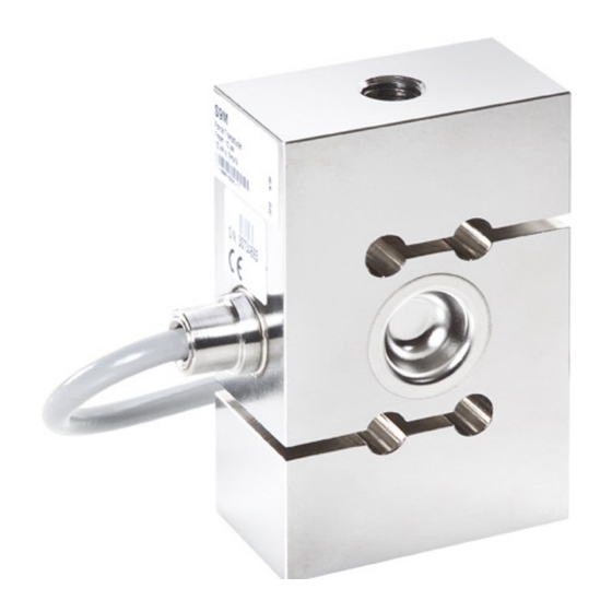
RSCC Structure and principle of operation The measuring element is a steel loaded member to which strain gauges (SG) are applied. The SG are arranged so that two are stretched and the other two compressed when a load acts on the transducer. Conditions on site 4.1 Ambient temperature The temperature effects on the zero signal and on the sensitivity are... - Page 9 RSCC NOTE Measurement errors may be the result if dust or dirt is deposited inside the load cells. The relevant areas are marked by arrows in Fig. 4.1. Fig. 4.1: Deposits at the marked areas must be avoided A3018-3.2 en/de/fr...
-
Page 10: Mechanical Installation
RSCC Mechanical installation 5.1 Mounting instructions When mounting the load cells, consider the following factors: The load cell must be handled carefully The load cell must not be overloaded, not even briefly Each load cell must be bridged with a copper wire either during or directly after installation to prevent welding currents flowing over the load cell Important The cable fastening side of the transducer should always be connected... -
Page 11: Load Application
Interference effects must be absorbed by suitable construction elements, whereby these elements must not absorb any loads in the load direction of the load cell. HBM recommends the use of knuckle eyes for connection without side force or moments. They are suitable for use with quasi‐static loading (load cycles v10 Hz). - Page 12 RSCC NOTE When locking, the tightening torque must not be shunted through the transducer. When using a knuckle eye, the following mounting dimensions apply: Rigid force transfer Fig. 5.2: Installation with one knuckle eye Maximum Knuckle eye (NVm) capacity 50 kg 1-U1R/200KG/ZGW 100 kg 1-U1R/200KG/ZGW...
- Page 13 RSCC When using two knuckle eyes, the following mounting dimensions apply: Rigid force transfer Fig. 5.3: Installation with two knuckle eyes Maximum Knuckle eye (NVm) capacity 50 kg 1-U1R/200KG/ZGW 100 kg 1-U1R/200KG/ZGW 200 kg 1-U2A/1T/ZGUW 500 kg 1-U2A/1T/ZGUW 1-U2A/1T/ZGUW 1-U2A/5T/ZGUW 1-U2A/5T/ZGUW A3018-3.2 en/de/fr...
-
Page 14: Electrical Connection
EMC guidelines. The shielding must be connected extensively. With other connection techniques, an EMC‐proof shield should be applied in the wire area and this shielding should also be connected extensively (also see HBM Greenline Information, brochure i1577). 6.2 Connection in a four‐wire configuration When load cells with a six‐wire configuration are connected to amplifiers with... -
Page 15: Extension Cable
RSCC leads due to the cable resistance that is still present and not compensated for by the six‐wire configuration. A large part of this loss can be eliminated by a calibration, however, the temperature‐dependent part remains. The TK value given in the specifications for the transducer therefore does not apply for the cable and transducer combination when connection is in a four‐wire configuration, as here the cable percentage must be added. - Page 16 RSCC Use shielded, low‐capacitance measurement cables only (HBM cables fulfill both conditions) Do not route the measurement cables parallel to power lines and control circuits. If this is not possible, protect the measurement cable with steel conduits, for example ...
-
Page 17: Specifications
RSCC Specifications Type RSCC Accuracy class as per OIML R 60 3000 No. of load cell verification intervals (n Maximum capacity (E 50 kg 100 kg 200 kg 500 kg Minimum load cell verification % of E 0.0120 interval (v Nominal (rated) sensitivity (C mV/V Sensitivity tolerance... -
Page 18: Dimensions
RSCC Dimensions 8.1 Load cells with maximum capacity 50 kg to 200 kg Dimensions (in mm; 1 mm = 0.03937 inches) Cable: Length 7.6 m Outside diameter 5 mm Material PVC Without adapter for cable protection system With adapter for cable protection system Maximum capacity 50 kg... -
Page 19: Load Cells With Maximum Capacity Range 500 Kg To 5 T
RSCC 8.2 Load cells with maximum capacity range 500 kg to 5 t Dimensions (in mm; 1 mm = 0.03937 inches) Cable: Length 7.6 m Outside diameter 5 mm Material PVC Without adapter for cable protection system With adapter for cable protection system Maximum capacity... -
Page 20: Mounting Aids
2 t to 5 t 1-U2A/5T/ 57.5 60 94.5 124.5 22 M24x2 31 10 ZGUW The permissible mechanical stresses of the knuckle eyes recommended by HBM are always at least as high as the permissible values given for the load cells. A3018-3.2 en/de/fr... - Page 21 RSCC Inhalt Seite Deutsch Sicherheitshinweise ..........Lieferumfang .
-
Page 22: Sicherheitshinweise
RSCC Sicherheitshinweise Wo bei Bruch Menschen und Sachen zu Schaden kommen können, müssen vom Anwender entsprechende Sicherheitsmaßnahmen (z. B. Absturzsiche rungen, Überlastsicherungen usw.) getroffen werden. Der einwandfreie und sichere Betrieb von Aufnehmern setzt sachgemäßen Transport, fachgerechte Lagerung, Aufstellung und Montage sowie sorgfältige Bedienung und Instand- haltung voraus. - Page 23 RSCC In dieser Montageanleitung wird auf Restgefahren mit den im Folgenden erläuterten Symbolen hingewiesen. Die folgende Kennzeichnung weist auf eine mögliche gefährliche Situation hin, die – wenn die Sicherheitsbestimmungen nicht beachtet werden – Tod oder schwere Körperverletzung zur Folge haben kann. WARNUNG Beschreibung einer möglicherweise gefährlichen Situation Maßnahmen zur Vermeidung/Abwendung der Gefahr...
- Page 24 RSCC Unfallverhütung Obwohl die angegebene Bruchlast ein Mehrfaches der Nennlast beträgt, müs- sen die einschlägigen Unfallverhütungsvorschriften der Berufsgenossen- schaften berücksichtigt werden. Berücksichtigen Sie insbesondere die in den technischen Daten angegebene Grenzlast (E Bruchlast (E Relative zulässige Schwingbeanspruchung (F srel A3018-3.2 en/de/fr...
-
Page 25: Lieferumfang
RSCC Lieferumfang 1 Wägezelle RSCC 1 Montageanleitung RSCC Zubehör (nicht im Lieferumfang enthalten): Gelenkösen zur Montage der Wägezellen RSCC mit den Nennlasten 50 kg 100 kg Bestellnr. 1-U1R/200KG/ZGW RSCC mit den Nennlasten 200 kg 1 t Bestellnr. -
Page 26: Aufbau Und Funktionsprinzip
RSCC Aufbau und Funktionsprinzip Das Messelement ist ein Verformungskörper aus Stahl, auf dem Dehnungs- messstreifen (DMS) angebracht sind. Die DMS sind so angeordnet, dass zwei von ihnen gedehnt und die zwei anderen gestaucht werden, wenn auf den Aufnehmer eine Last einwirkt. Bedingungen am Einsatzort 4.1 Umgebungstemperatur Die Temperatureinflüsse auf das Nullsignal sowie auf den Kennwert sind kom-... - Page 27 RSCC HINWEIS Fehlmessungen können die Folge sein, wenn sich Staub oder Schmutz innerhalb der Wägezellen ablagern. Die betreffenden Stellen sind in Abb. 4.1 mit Pfeilen markiert. Abb. 4.1: Ablagerungen an den gekennzeichneten Stellen sind zu vermeiden A3018-3.2 en/de/fr...
-
Page 28: Mechanischer Einbau
RSCC Mechanischer Einbau 5.1 Montagehinweise Bei der Montage der Wägezellen sind folgende Punkte zu beachten: Die Wägezelle muss schonend gehandhabt werden Die Wägezelle darf nicht überlastet werden, auch nicht kurzzeitig Jede Wägezelle sollte während oder unmittelbar nach dem Einbau durch eine Kupferlitze überbrückt werden, damit keine Schweißströme über die Wägezelle fließen können Wichtig... -
Page 29: Lasteinleitung
Elemente keine Lasten in Lastrichtung der Wägezelle aufnehmen dürfen. Für einen seitenkraft‐ und momentenfreien Anschluss empfiehlt HBM die Verwendung von Gelenkösen. Sie eignen sich für den Einsatz bei quasistatischer Belastung (Lastwechsel v10 Hz). 5.3 Montage mittels Gelenkösen Gelenkösen verhindern die Einleitung von Torsionsmomenten und –... - Page 30 RSCC HINWEIS Beim Kontern darf das Anzugsmoment keinesfalls durch den Aufnehmer hin- durch geleitet werden. Bei der Benutzung einer Gelenköse ergeben sich folgende Einbaumaße: starre Kraftausleitung Abb. 5.2: Einbau mit einer Gelenköse Nennlast Gelenköse (NVm) 50 kg 1-U1R/200KG/ZGW 100 kg 1-U1R/200KG/ZGW 200 kg 1-U2A/1T/ZGUW...
- Page 31 RSCC Bei der Benutzung von zwei Gelenkösen ergeben sich folgende Einbaumaße: starre Kraftausleitung Abb. 5.3: Einbau mit zwei Gelenkösen Nennlast Gelenköse (NVm) 50 kg 1-U1R/200KG/ZGW 100 kg 1-U1R/200KG/ZGW 200 kg 1-U2A/1T/ZGUW 500 kg 1-U2A/1T/ZGUW 1-U2A/1T/ZGUW 1-U2A/5T/ZGUW 1-U2A/5T/ZGUW A3018-3.2 en/de/fr...
-
Page 32: Elektrischer Anschluss
EMV-Richtlinien entsprechen. Die Schirmung ist dabei flächig aufzulegen. Bei anderen Anschlusstechniken ist im Litzenbereich eine EMV-feste Abschir- mung vorzusehen, bei der ebenfalls die Schirmung flächig aufzulegen ist (siehe auch HBM-Greenline-Information, Druckschrift i1577). 6.2 Anschluss in Vierleiter‐Technik Wenn Sie Wägezellen, die in Sechsleiter‐Technik ausgeführt sind, an Verstär- ker mit Vierleiter‐Technik anschließen, müssen Sie die Fühlerleitungen der... -
Page 33: Kabelverlängerung
RSCC Diese Maßnahme verkleinert unter anderem den Kabelwiderstand der Speisespannungsleitungen. Es entsteht jedoch durch den immer noch vor- handenen und nicht durch die Sechsleiter-T echnik kompensierten Kabel- widerstand ein Spannungsverlust auf den Speiseleitungen. Ein Großteil dieses Verlustes kann durch eine Kalibrierung eliminiert werden, es verbleibt jedoch der temperaturabhängige Anteil. -
Page 34: Emv-Schutz
6.5 EMV‐Schutz Elektrische und magnetische Felder verursachen oft eine Einkopplung von Störspannungen in den Messkreis. Deshalb: verwenden Sie nur abgeschirmte, kapazitätsarme Messkabel (HBM‐Kabel erfüllen diese Bedingungen) legen Sie die Messkabel nicht parallel zu Starkstrom‐ und Steuerleitungen. Falls das nicht möglich ist, schützen Sie das Messkabel, z. B. durch Stahlpanzerrohre ... -
Page 35: Technische Daten
RSCC Technische Daten RSCC Genauigkeitsklasse nach OIML R 60 3000 Anzahl der Teilungswerte (n Nennlast (E 50 kg 100 kg 200 kg 500kg Mindestteilungswert (v % v. E 0,0120 Nennkennwert (C mV/V Kennwerttoleranz "0,25 Nullsignal mV/V 0 "0,1 Temperaturkoeffizient des "0,0170 (20C ... -
Page 36: Abmessungen
RSCC Abmessungen 8.1 Wägezellen mit Nennlastbereich 50 kg bis 200 kg Abmessungen (in mm) Kabel: Länge 7,6 m Außendurchmesser 5 mm Werkstoff PVC ohne Adapter für Kabelschutzsystem mit Adapter für Kabelschutzsystem Nennlast 50 kg 50,8 25,4 100 kg 50,8 25,4 200 kg 87,3 57,2... -
Page 37: Wägezellen Mit Nennlastbereich 500 Kg Bis 5 T
RSCC 8.2 Wägezellen mit Nennlastbereich 500 kg bis 5 t Abmessungen (in mm) Kabel: Länge 7,6 m Außendurchmesser 5 mm Werkstoff PVC ohne Adapter für Kabelschutzsystem mit Adapter für Kabelschutzsystem Nennlast 500 kg 87,3 57,2 28,6 43,7 87,3 57,2 28,6 43,7 69,8 34,9... -
Page 38: Einbauhilfen
ZGUW 2 t 5 t 1-U2A/5T/ 57,5 60 94,5 124,5 22 M24x2 31 10 ZGUW Die zulässigen mechanischen Beanspruchungen der von HBM empfohlenen Gelenkösen sind immer mindestens so hoch wie die für die Wägezelle angegebenen zulässigen Werte. A3018-3.2 en/de/fr... - Page 39 RSCC Sommaire Page Français Consignes de sécurité ......... . . Etendue de la livraison .
-
Page 40: Consignes De Sécurité
RSCC Consignes de sécurité Dans les cas où une rupture serait susceptible de provoquer des dommages corporels et matériels, l'utilisateur se doit de prendre les mesures de sécurité qui s'imposent (p. ex. dispositifs antichute, protections contre les surcharges, etc.). Afin de garantir un fonctionnement parfait et en toute sécurité des capteurs, il convient de veiller à... - Page 41 RSCC constructeur/l'opérateur de manière à minimiser les dangers résiduels. Les dispositions correspondantes en vigueur doivent être respectées. Il convient d'attirer l'attention sur les dangers résiduels liés à la technique de pesage. Dans la présente notice de montage, les dangers résiduels sont signalés à l'aide des symboles décrits ci‐après : Le marquage suivant signale un risque potentiel qui - si les dispositions relatives à...
- Page 42 RSCC Personnel qualifié On appelle “personnel qualifié" les personnes possédant des connaissances suffisantes dans le domaine requis en raison de leur formation spécialisée et connaissent également les réglementations nationales du travail et de la prévention des accidents correspondantes, les directives et les règles techniques reconnues.
-
Page 43: Etendue De La Livraison
RSCC Etendue de la livraison 1 peson RSCC 1 notice de montage RSCC Accessoires (ne faisant pas partie de la livraison) : Anneaux à rotule pour le montage des pesons RSCC avec les charges nominales 50 kg 100 kg N°... -
Page 44: Conception Et Principe De Fonctionnement
RSCC Conception et principe de fonctionnement L'élément de mesure est un corps de déformation en acier sur lequel sont posées des jauges d'extensométrie. Les jauges sont disposées de façon à ce que deux d'entre elles soient allongées et les deux autres comprimées lorsqu'une charge agit sur le capteur. - Page 45 RSCC NOTE Des erreurs de mesure peuvent se produire lorsque de la poussière ou des saletés se déposent à l'intérieur des pesons. Les zones concernées sont repérées par des flèches sur la Fig. 4.1. Fig. 4.1: Éviter les dépôts aux endroits signalés A3018-3.2 en/de/fr...
-
Page 46: Montage Mécanique
RSCC Montage mécanique 5.1 Instructions de montage Lors du montage des pesons, les points suivants doivent être respectés : Le peson doit être manié avec ménagement Une surcharge même brève du peson n'est pas autorisée Pendant ou immédiatement avant le montage, un pontage de tout peson par toron en cuivre est nécessaire, pour qu'aucun courant de soudage ne puisse passer par le peson. -
Page 47: Application De Charge
éléments ne doivent pas capter de charges dans le sens de charge du peson. Pour un raccordement exempt de force latérale et de moment, HBM recommande d'utiliser des anneaux à rotule. Les anneaux à rotule conviennent pour un usage avec une charge quasi‐statique (charge alternée v10 Hz). - Page 48 RSCC 2. Visser l'anneau à rotule dans le capteur (respecter la longueur de filet adm.). 3. Orienter l'anneau à rotule 4. Serrer le contre‐écrou avec le couple indiqué ci‐après Charge nominale Filetage au niveau du peson Couple de serrage (NVm) (kg) 50 ...
- Page 49 RSCC Avec un anneau à rotule, on a les cotes de montage suivantes : Transfert de force rigide Fig. 5.2: Montage avec un anneau à rotule Charge Anneau à rotule (NVm) nom. 50 kg 1-U1R/200KG/ZGW 100 kg 1-U1R/200KG/ZGW 200 kg 1-U2A/1T/ZGUW 500 kg 1-U2A/1T/ZGUW...
- Page 50 RSCC Avec deux anneaux à rotule, on a les cotes de montage suivantes : Transfert de force rigide Fig. 5.3: Montage avec deux anneaux à rotule Charge nom. Anneau à rotule (NVm) 50 kg 1-U1R/200KG/ZGW 100 kg 1-U1R/200KG/ZGW 200 kg 1-U2A/1T/ZGUW 500 kg 1-U2A/1T/ZGUW...
-
Page 51: Raccordement Électrique
CEM dans la zone des fils torsadés, celui‐ci devant également être posé en nappe (voir aussi les informations Greenline de HBM, brochure i1577). 6.2 Raccordement en technique quatre fils Lors du raccordement de pesons en technique six fils à un amplificateur en technique quatre fils, il est nécessaire de relier les fils de contre‐réaction des... -
Page 52: Rallonge De Câble
RSCC liée à la résistance intrinsèque encore présente et non compensée par la technique 6 fils, se produit sur tous les fils d'alimentation. La majeure partie de cette perte peut être éliminée par un calibrage, cependant la partie dépendant de la température reste. Le TK indiqué... -
Page 53: Protection Cem
: utiliser uniquement des câbles de mesure blindés de faible capacité (les câbles HBM satisfont à ces conditions). absolument éviter de poser les câbles de mesure en parallèle avec des lignes de puissance et de contrôle. Si cela n'est pas possible, protéger le câble de mesure, par ex. -
Page 54: Caractéristiques Techniques
RSCC Caractéristiques techniques Type RSCC Classe de précision selon OIML R 60 3000 Nombre de graduations (n Charge nominale (E 50 kg 100 kg 200 kg 500kg Valeur min. d'un échelon (v % d'E 0,0120 Sensibilité nominale (C mV/V Tolérance de sensibilité "0,25 Zéro mV/V... -
Page 55: Dimensions
RSCC Dimensions 8.1 Pesons ayant une plage de charge nominale de 50 kg à 200 kg Dimensions (en mm) Câble : Longueur 7,6 m Diamètre ext. 5 mm Matériau PVC sans adaptateur pour système de protection de câble avec adaptateur pour système de protection de câble Charge nom. - Page 56 RSCC 8.2 Pesons ayant une plage de charge nominale de 500 kg à 5 t Dimensions (en mm) Câble : Longueur 7,6 m Diamètre ext. 5 mm Matériau PVC sans adaptateur pour système de protection de câble avec adaptateur pour système de protection de câble Charge nom.
-
Page 57: Accessoires De Montage
2 t 5 t 1-U2A/5T/ 57,5 60 94,5 124,5 22 M24x2 31 10 ZGUW Les sollicitations mécaniques autorisées des anneaux à rotule recommandés par HBM sont toujours au moins aussi élevées que les valeurs admissibles indiquées pour le peson. A3018-3.2 en/de/fr... - Page 58 RSCC A3018-3.2 en/de/fr...
- Page 60 Elles n'établissent aucune assurance formelle au terme de la loi et n'engagent pas notre responsabilité. Hottinger Baldwin Messtechnik GmbH Im Tiefen See 45 S 64293 Darmstadt S Germany Tel. +49 6151 803-0 S Fax: +49 6151 803-9100 Email: info@hbm.com www.hbm.com...
Need help?
Do you have a question about the RSCC Series and is the answer not in the manual?
Questions and answers