Sign In
Upload
Manuals
Brands
HBM Manuals
Accessories
T40FH
HBM T40FH Manuals
Manuals and User Guides for HBM T40FH. We have
1
HBM T40FH manual available for free PDF download: Mounting Instructions
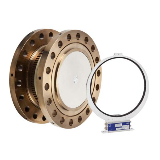
HBM T40FH Mounting Instructions (140 pages)
Brand:
HBM
| Category:
Accessories
| Size: 0.92 MB
Table of Contents
English
4
Table of Contents
4
Safety Instructions
6
Markings Used
12
Symbols on the Transducer
12
The Markings Used in this Document
13
Application
14
Structure and Mode of Operation
15
Important Precautions During Installation
17
Mechanical Installation
17
Conditions on Site
18
Mounting Position
18
Installation Options
19
Installation with Antenna Ring Removed
20
Preparing for the Rotor Mounting
21
Mounting the Rotor
24
Installing the Stator
27
Rotational Speed Measuring System
31
Electrical Connection
33
General Information
33
EMC Protection
33
Connector Pin Assignment Option 4, Code SU2, DU2, HU2
34
Connector Pin Assignment Option 3, Code PNJ
39
Supply Voltage (SU2, DU2, HU2)
39
Supply Voltage (Option 3, Code PNJ)
40
TEDS Transducer Identification (Option 3, Code PNJ)
41
Hierarchy of User Rights
41
Administrator Rights (ID Level)
41
Contents of the TEDS Memory as Defined in IEEE 1451.4
42
Calibration Rights (CAL Level)
41
Standard Rights (USR Level)
41
Shunt Signal
46
Functionality Testing
47
Rotor Status, LED a (Upper LED)
47
Stator Status, LED B (Lower LED)
48
Load-Carrying Capacity
49
Maintenance
50
Waste Disposal and Environmental Protection
51
13.1.1 T40FH 100 Knm - 150 Knm
52
Dimensions
52
T40FH Torque Transducer with Rotational Speed Measuring System, Option 4, Code SU2, DU2, HU2
52
13.1.2 T40FH 200 Knm - 300 Knm
54
13.2.1 T40FH 100 Knm - 150 Knm
56
Option 4, Code PNJ
56
T40FH Torque Transducer (Non-Rotating)
56
13.2.2 T40FH 200 Knm - 300 Knm
58
Ordering Numbers, Accessories
60
Specifications
62
Supplementary Technical Information
70
Deutsch
72
Sicherheitshinweise
74
Auf dem Aufnehmer Angebrachte Symbole
80
Verwendete Kennzeichnungen
80
In dieser Anleitung Verwendete Kennzeichnungen
81
Anwendung
82
Aufbau und Wirkungsweise
83
Mechanischer Einbau
85
Wichtige Vorkehrungen Beim Einbau
85
Bedingungen am Einbauort
86
Einbaulage
86
Einbaumöglichkeiten
87
Einbau mit Demontiertem Antennenring
88
Rotormontage Vorbereiten
89
Montage des Rotors
92
Montage des Stators
95
Drehzahlmesssystem
100
Elektrischer Anschluss
102
Allgemeine Hinweise
102
EMV-Schutz
102
Steckerbelegung Option 4, Code SU2, DU2, HU2
103
Steckerbelegung Option 3, Code PNJ
108
Versorgungsspannung (SU2, DU2, HU2)
108
Versorgungsspannung (Option 3, Code PNJ)
109
Aufnehmer-Identifikation TEDS (Option 3, Code PNJ)
110
Hierarchie der Nutzerrechte
110
Administratorrechte (Stufe ID)
110
Inhalt des TEDS-Speicher nach IEEE 1451.4
111
Kalibrierrechte (Stufe CAL)
110
Standardrechte (Stufe USR)
110
Shuntsignal
115
Funktionsprüfung
116
Rotorstatus, LED a (Obere LED)
116
Statorstatus, LED B (Untere LED)
117
Belastbarkeit
118
Wartung
119
Entsorgung und Umweltschutz
120
13.1.1 T40FH 100 Knm - 150 Knm
121
Abmessungen
121
T40FH Drehmomentaufnehmer mit Drehzahlmesssystem, Option 4, Code SU2, DU2, HU2
121
13.1.2 T40FH 200 Knm - 300 Knm
123
13.2.1 T40FH 100 Knm - 150 Knm
125
Option 4, Code PNJ
125
T40FH Drehmomentaufnehmer (nicht Drehend)
125
13.2.2 T40FH 200 Knm - 300 Knm
127
Bestellnummern, Zubehör
129
Technische Daten
132
Ergänzende Technische Informationen
139
Advertisement
Advertisement
Related Products
HBM T10FM
HBM T40B
HBM T40FM
HBM T40S7
HBM T40S8
HBM T40S9
HBM T4A
HBM T4WA-S3
HBM T40
HBM T40MS
HBM Categories
Transducer
Measuring Instruments
Accessories
Amplifier
Industrial Equipment
More HBM Manuals
Login
Sign In
OR
Sign in with Facebook
Sign in with Google
Upload manual
Upload from disk
Upload from URL