Table of Contents
Advertisement
Advertisement
Table of Contents

Related Manuals for DURKOPP ADLER 171


Summary of Contents for DURKOPP ADLER 171
- Page 1 171 / 173 Operating Instructions...
- Page 2 IMPORTANT READ CAREFULLY BEFORE USE KEEP FOR FUTURE REFERENCE All rights reserved. Property of Dürkopp Adler AG and protected by copyright. Any reuse of these contents, including extracts, is prohibited without the prior written approval of Dürkopp Adler AG. Copyright © Dürkopp Adler AG 2019...
-
Page 3: Table Of Contents
Edge pinker (optional) ................. 47 4.12 Adjusting the edge guide..............48 4.12.1 4.12.2 Adjusting the height of the chain cutter guard ........49 4.12.3 Deactivating the edge pinker ............... 50 4.12.4 Disassembling the edge pinker ............51 Operating Instructions 171/173 - 02.0 - 09/2019... - Page 4 Pneumatic connection ................. 87 7.13.1 Assembling the compressed air maintenance unit ......88 Setting the operating pressure ............89 7.13.2 7.14 Performing a test run ................90 Decommissioning ................91 Disposal ..................... 93 Operating Instructions 171/173 - 02.0 - 09/2019...
- Page 5 Errors in sewing process ..............96 Technical data ................... 99 11.1 Data and characteristic values ............100 11.2 Requirements for trouble-free operation ........... 101 Appendix ..................103 12.1 Table drawing..................103 12.2 Wiring diagram .................. 104 Operating Instructions 171/173 - 02.0 - 09/2019...
- Page 6 Table of Contents Operating Instructions 171/173 - 02.0 - 09/2019...
-
Page 7: About These Instructions
Setup ( p. 71) is important for specialists. Service Instructions are supplied separately. With regard to minimum qualification and other requirements to be met by personnel, please also follow the chapter Safety ( p. 9). Operating Instructions 171/173 - 02.0 - 09/2019... -
Page 8: Representation Conventions - Symbols And Characters
Lists are marked by bullet points. Result of performing an operation Change to the machine or on the display/control panel. Important Special attention must be paid to this point when performing a step. Operating Instructions 171/173 - 02.0 - 09/2019... -
Page 9: Other Documents
Each manufacturer has performed a hazard assessment for these purchased parts and confirmed their design compliance with applicable European and national regulations. The proper use of the built-in components is described in the corresponding manu- facturer's instructions. Operating Instructions 171/173 - 02.0 - 09/2019... -
Page 10: Liability
Leave machines, equipment and packaging material in the con- dition in which they were found when the damage was discovered. This will ensure any claims against the transport company. Report all other complaints to Dürkopp Adler immediately after receiving the product. Operating Instructions 171/173 - 02.0 - 09/2019... -
Page 11: Safety
The power plug may only be assembled to the power cable by qualified specialists. Obligations Follow the country-specific safety and accident prevention regu- of the operator lations and the legal regulations concerning industrial safety and the protection of the environment. Operating Instructions 171/173 - 02.0 - 09/2019... -
Page 12: Signal Words And Symbols Used In Warnings
Signal words Signal words and the hazard they describe: Signal word Meaning DANGER (with hazard symbol) If ignored, fatal or serious injury will result WARNING (with hazard symbol) If ignored, fatal or serious injury can result Operating Instructions 171/173 - 02.0 - 09/2019... - Page 13 If ignored, environmental damage can result NOTICE (without hazard symbol) If ignored, property damage can result Symbols The following symbols indicate the type of danger to personnel: Symbol Type of danger General Electric shock Puncture Crushing Environmental damage Operating Instructions 171/173 - 02.0 - 09/2019...
- Page 14 Type and source of danger! Consequences of non-compliance. Measures for avoiding the danger. This is what a warning looks like for a hazard that could result in moderate or minor injury if the warning is ignored. Operating Instructions 171/173 - 02.0 - 09/2019...
- Page 15 CAUTION Type and source of danger! Consequences of non-compliance. Measures for avoiding the danger. This is what a warning looks like for a hazard that could result in environmental damage if ignored. Operating Instructions 171/173 - 02.0 - 09/2019...
- Page 16 Safety Operating Instructions 171/173 - 02.0 - 09/2019...
-
Page 17: Machine Description
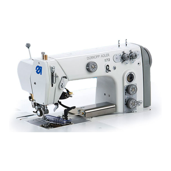
⑤ (1) - Machine head (6) - Maintenance unit (2) - Table top (7) - Setpoint device (3) - Drawer (8) - Control (4) - Stand (9) - Reel stand (5) - Pedal Operating Instructions 171/173 - 02.0 - 09/2019... -
Page 18: Proper Use
The needle thicknesses permissible for the machine are listed in the Technical data ( p. 99) chapter. The seam must be completed with a thread that satisfies the requirements of the specific application at hand. The machine is intended for industrial use. Operating Instructions 171/173 - 02.0 - 09/2019... -
Page 19: Declaration Of Conformity
Dürkopp Adler cannot be held liable for damages resulting from improper use. Declaration of Conformity The machine complies with European regulations ensuring health, safety, and environmental protection as specified in the declara- tion of conformity or in the declaration of incorporation. Operating Instructions 171/173 - 02.0 - 09/2019... - Page 20 Machine description Operating Instructions 171/173 - 02.0 - 09/2019...
-
Page 21: Operation
Complete the following steps in preparation of sewing before starting to work: • Inserting/changing the needle • Threading the needle thread • Inserting and winding on the looper thread • Setting the thread tension Operating Instructions 171/173 - 02.0 - 09/2019... -
Page 22: Switching On And Off The Machine
Press the main switch (1) into position I. The LED (2) lights up. To switch off the machine: Press the main switch (1) into position 0. The LED (2) goes off. Operating Instructions 171/173 - 02.0 - 09/2019... -
Page 23: Inserting Or Replacing The Needle
Turn the handwheel until the needle bar (1) reaches the top dead centre. Loosen screw (2). Pull the needle out downwards. Insert the new needle. Important Align the needle so that the groove (3) faces to the rear. Tighten screw (2). Operating Instructions 171/173 - 02.0 - 09/2019... -
Page 24: Threading The Needle Thread
Fit the thread reel on the left plate of the reel stand (2). Thread the thread in a wavelike manner through the holes of the thread guide. Important The thread guide (1) must be parallel to the reel stand (2). Operating Instructions 171/173 - 02.0 - 09/2019... - Page 25 Insert the thread through the thread guide (6). Insert the thread from the right to the left through the thread advancing device (7). Operating Instructions 171/173 - 02.0 - 09/2019...
- Page 26 (9). 12. Feed the thread from above downwards through the thread guide (13). 13. Feed the thread from above forwards and downwards to the rear through the thread guide (11). Operating Instructions 171/173 - 02.0 - 09/2019...
-
Page 27: Threading The Looper Thread
Move the lever (2) to the right. Make sure the lever (2) snaps into place. Loosen the screw (1). Press the pedal back. The sewing foot is lifted. The edge pinker (3) can be removed completely. Operating Instructions 171/173 - 02.0 - 09/2019... - Page 28 Fit the thread reel on the right plate of the reel stand (2). Fit the thread in a wavelike manner through the holes of the thread guide (1). Important The thread guide (1) must be parallel to the reel stand (2). Operating Instructions 171/173 - 02.0 - 09/2019...
- Page 29 (4) to thread guide (6). By pressing on the tension opener (7), the tension can be opened to allow the thread to be fed around. Operating Instructions 171/173 - 02.0 - 09/2019...
- Page 30 15. Insert the thread from left to right through the looper hole (11) and pull out approx. 3 cm. 16. Press down the thread down-holder (10) and engage. 17. Fit the cover plates to the right and left of the throat plate. Operating Instructions 171/173 - 02.0 - 09/2019...
-
Page 31: Threading Twin-Needle Machines
The threading procedure corresponds to that for the single-needle machines. Important Take care when threading the machine that the threads do not cross over one another Operating Instructions 171/173 - 02.0 - 09/2019... -
Page 32: Thread Tension
• Normal seams (2) • Highly elastic seams (balloon stitch) (3) Fig. 12: Thread tension ① ② ③ (1) - Tight seam (3) - Highly elastic seam (2) - Normal seam (balloon stitch) Operating Instructions 171/173 - 02.0 - 09/2019... -
Page 33: Setting The Needle Thread Tension
To set the needle thread tension: Turn the adjusting wheel (1). • increasing the needle thread tension: turn the adjusting wheel (1) clockwise • decreasing the needle thread tension: turn the adjus- ting wheel (1) counterclockwise Operating Instructions 171/173 - 02.0 - 09/2019... -
Page 34: Setting The Looper Thread Tension
The required thread quantity depends on the thickness of the sewing material, thread strength and seam type. For different threads and seam types, the threading procedure also differs ( p. 22). Operating Instructions 171/173 - 02.0 - 09/2019... - Page 35 To set the needle thread regulator: Turn the handwheel until the thread lever reaches its lower end position. Loosen the screws (1). Move the needle thread regulator (2) to the correct position. Tighten the screws (1). Operating Instructions 171/173 - 02.0 - 09/2019...
-
Page 36: Setting The Looper Thread Take-Up
In particular for extreme settings (e. g. highly elastic seams), it must be ensured that the looper thread quantity is not too large. To set the looper thread take-up: Switch off the machine. Tilt the machine head. Loosen the screws (4). Operating Instructions 171/173 - 02.0 - 09/2019... -
Page 37: Stitch Length
The stitch length can be adjusted by turning the adjusting wheel continuously between 1 and 4 mm. Fig. 17: Setting the stitch length (1) ① ② (1) - Adjusting mark (2) - Stitch length adjusting wheel Operating Instructions 171/173 - 02.0 - 09/2019... - Page 38 Crushing possible. Switch off the machine before setting the stitch length. The subclass 171-131610 does not have adjusting wheels for the stitch length. Here, the stitch length is adjusted on the machine underside. Fig. 18: Setting the stitch length (2), Subclass 171-131610 ①...
-
Page 39: Setting The Stitch Condensing
For machines with pushbuttons on the machine arm ( p. 52) it is possible to switch over to stitch condensing while sewing. The stitch length for stitch condensing can be adjusted by turning the adjusting wheel continuously between 1 and 4 mm. Operating Instructions 171/173 - 02.0 - 09/2019... - Page 40 • increasing the stitch length: turn the stitch length adjus- ting wheel (2) counterclockwise • decreasing the stitch length: turn the stitch length adjusting wheel (2) clockwise The adjusting mark (1) indicates the selected stitch length. Operating Instructions 171/173 - 02.0 - 09/2019...
-
Page 41: Sewing Feet
To set the sewing foot pressure: Turn the adjusting wheel (1). • increasing the sewing foot pressure: turn the adjusting wheel (1) clockwise • decreasing the sewing foot pressure: turn the adjusting wheel (1) counterclockwise Operating Instructions 171/173 - 02.0 - 09/2019... -
Page 42: Lifting The Sewing Foot
To lift the sewing foot with the pedal: Press the pedal (2) half-way back. The sewing foot is lifted. The sewing foot remains up as long as the pedal is kept in that position. Operating Instructions 171/173 - 02.0 - 09/2019... -
Page 43: Locking The Sewing Foot At The Top Dead Centre
To lock the sewing foot at the top dead centre: Lift the sewing foot ( p. 40). Press the locking button (1). Release the knee lever or pedal. The sewing foot is locked at the top dead centre. Operating Instructions 171/173 - 02.0 - 09/2019... -
Page 44: Roller Top Feed (Optional)
Information When sewing the stitch condensing at the start and end of the seam, the roller top feed is automatically adjusted to the shortened bottom feed. Operating Instructions 171/173 - 02.0 - 09/2019... -
Page 45: Setting The Roller Top Feed Length
• increasing the roller top feed length: turn the adjusting wheel (1) counterclockwise • decreasing the roller top feed length: turn the adjusting wheel (1) clockwise The adjusting mark (1) indicates the selected value. Operating Instructions 171/173 - 02.0 - 09/2019... -
Page 46: Setting The Pressure Of The Carrier Roller
The sewing material does not slip and is fed through correctly. Fig. 24: Setting the pressure of the carrier roller ① ② ③ ④ (1) - Cylinder (3) - Fabric deflector (2) - Screw (4) - Carrier roller Operating Instructions 171/173 - 02.0 - 09/2019... - Page 47 Tighten the screw (2). Information Separating the thread chain without a thread cutter For machines without a thread cutter, the fabric deflector (3) can be used during linking as a cutting knife for the thread chain. Operating Instructions 171/173 - 02.0 - 09/2019...
-
Page 48: Lifting The Carrier Roller
The LED on the button (3) goes out. The carrier roller (2) is lowered. To lift the carrier roller completely: Pull the lever (1) to the front. The lever (1) engages. The carrier roller (2) is completely raised. Operating Instructions 171/173 - 02.0 - 09/2019... -
Page 49: Edge Pinker (Optional)
Risk of injury from sharp parts! Cutting injuries may be sustained. NEVER reach into the area of the triangular knife. CAUTION Risk of injury from moving parts! Crushing possible. NEVER reach into the area of the chain cutter. Operating Instructions 171/173 - 02.0 - 09/2019... -
Page 50: Adjusting The Edge Guide
Fig. 26: Adjusting the edge guide ① ② (1) - Edge guide (2) - Screw To adjust the edge guide: Loosen the screw (2). Shift the edge guide (1) laterally. Tighten the screw (2). Operating Instructions 171/173 - 02.0 - 09/2019... -
Page 51: Adjusting The Height Of The Chain Cutter Guard
Loosen the screw (1). Adjust the height of the chain cutter guard (2). Tighten the screw (1). The chain cutter guard (2) cannot be positioned higher than 8 mm above the throat plate. Operating Instructions 171/173 - 02.0 - 09/2019... -
Page 52: Deactivating The Edge Pinker
Fig. 28: Deactivating the edge pinker ① ① (1) - Lever To deactivate the edge pinker: Move the lever (1) to the right. Make sure the lever (1) snaps into place. The edge pinker has been deactivated. Operating Instructions 171/173 - 02.0 - 09/2019... -
Page 53: Disassembling The Edge Pinker
Move the lever (2) to the right. Make sure the lever (2) snaps into place. Loosen the screw (1). Press the pedal back. The sewing foot is lifted. The edge pinker (3) can be removed completely. Operating Instructions 171/173 - 02.0 - 09/2019... -
Page 54: Buttons On The Machine Arm
As long as the roller is raised, the yellow LED next to the button lights up. Yellow LED: lights when function is activated Green LED: lights when the sewing drive is switched on Operating Instructions 171/173 - 02.0 - 09/2019... -
Page 55: Sewing
• The last sewing process is completed by cutting off the thread. Fig. 31: Sewing ① (1) - Pedal To sew: Press the pedal (1) to POS. -1. Lift the sewing feet. Slide the sewing material up to the needle. Operating Instructions 171/173 - 02.0 - 09/2019... - Page 56 Press the pedal to POS. -2 and hold it down. The thread is cut off. The machine stops. The needle is up. The sewing feet are raised. Release the pedal and remove the sewing material. Operating Instructions 171/173 - 02.0 - 09/2019...
-
Page 57: Programming
(1) - Power LED (5) - Seam program button group (2) - Thread button group (6) - LED for 2 stitch length (3) - Function button (7) - Display (4) - Programming button group Operating Instructions 171/173 - 02.0 - 09/2019... - Page 58 Sewing foot lift after • Activates or deactivates sewing stop the sewing foot lift after sewing stops Soft start • Activates or deactivates the soft start Operating Instructions 171/173 - 02.0 - 09/2019...
- Page 59 • Changes to next higher category • Selects subprogram • Increases parameter • Selects subprogram • Increases parameter • Selects subprogram • Calls parameter or saves it • Starts or ends the parameter mode Operating Instructions 171/173 - 02.0 - 09/2019...
- Page 60 • Selects subprogram • Decreases parameter • Changes to next lower category • Selects subprogram • Decreases parameter • Selects subprogram • Decreases parameter • Selects subprogram Reset • Resets the (piece) counter Operating Instructions 171/173 - 02.0 - 09/2019...
- Page 61 Programming Button Function Seam program button group Seam program I • Activates seam program I Seam program II • Activates seam program II Seam program III • Sets seam program III Operating Instructions 171/173 - 02.0 - 09/2019...
-
Page 62: Edge Pinker
1 = ON Technician level t 13 01 Switch-off delay suction Value range: 9,999 - 2,500 seconds 5.1.2 Activating the chain cutter To activate the chain cutter, press the button on the control panel. Operating Instructions 171/173 - 02.0 - 09/2019... -
Page 63: Maintenance
( Service Instructions). Maintenance intervals Work to be carried out Operating hours Removing lint and thread remnants Check the oil Check the lubrication of the looper Servicing the pneumatic system Operating Instructions 171/173 - 02.0 - 09/2019... -
Page 64: Cleaning
• Area under the throat plate • Area around the looper • Area around the thread take-up disk • Thread trimmer • Area around the needle • Air inlet openings on the motor fan sieve • Oil pan Operating Instructions 171/173 - 02.0 - 09/2019... -
Page 65: Lubricating
Carefully collect up used oil. Dispose of used oil and oily machine parts in accordance with national regulations. The machine is equipped with a central oil-wick lubrication system. The bearings are supplied from the oil reservoir. Operating Instructions 171/173 - 02.0 - 09/2019... -
Page 66: Lubricating The Machine Head
② ③ (1) - Refill opening (3) - MIN-marking (2) - MAX-marking To lubricate the machine head: Switch off the machine head. Pour oil through the refill opening (1) to the MAX-marking (2). Operating Instructions 171/173 - 02.0 - 09/2019... -
Page 67: Lubricating The Looper
(4) - MIN-marking To lubricate the looper: Switch off the machine. Tilt the machine head. Loosen the screw (1). Pour in oil to the MAX-marking (3). Tighten the screw (1). Erect the machine head. Operating Instructions 171/173 - 02.0 - 09/2019... -
Page 68: Servicing The Pneumatic System
Check the operating pressure on a daily basis. Fig. 35: Setting the operating pressure ① ② (1) - Pressure controller (2) - Pressure gage To set the operating pressure: Pull the pressure controller (1) up. Operating Instructions 171/173 - 02.0 - 09/2019... -
Page 69: Draining The Water-Oil Mixture
Check the level of the water-oil mixture in the collection tray (2). Fig. 36: Draining the water-oil mixture ① ② ③ (1) - Filter element (3) - Drain screw (2) - Collection tray Operating Instructions 171/173 - 02.0 - 09/2019... -
Page 70: Cleaning The Filter Element
(3) - Drain screw (2) - Collection tray To clean the filter element: Disconnect the machine from the compressed air supply. Drain the water-oil mixture ( p. 67). Unscrew the collection tray (2). Operating Instructions 171/173 - 02.0 - 09/2019... -
Page 71: Parts List
Tighten the drain screw (3). 10. Connect the machine to the compressed air supply. Parts list A parts list can be ordered from Dürkopp Adler. Or visit our website for further information at: www.duerkopp-adler.com Operating Instructions 171/173 - 02.0 - 09/2019... - Page 72 Maintenance Operating Instructions 171/173 - 02.0 - 09/2019...
-
Page 73: Setup
• Lashing straps and wooden blocks from the machine head • Lashing straps and wooden blocks from the table • Lashing straps and wooden blocks from the stand • Supporting wedges between the machine arm and the throat plate Operating Instructions 171/173 - 02.0 - 09/2019... -
Page 74: Assembling The Stand
Push the stand frame feet (5) onto the foot struts (6). Important The frame must sit evenly on the ground with all 4 feet. Tighten the screws (8). Screw the oil can holder (2) at the rear to the upper cross bar (4). Operating Instructions 171/173 - 02.0 - 09/2019... -
Page 75: Tabletop
Fig. 39: Completing the tabletop ① ② ⑥ ③ ④ ⑤ (1) - Machine head support (only 171) (4) - Cable duct (2) - Rubber mounts (5) - Oil pan (3) - Drawer (6) - Corners To complete the tabletop: Insert the machine head support (1) in the hole of the table plate. -
Page 76: Assembling The Tabletop To The Stand
Assembling the tabletop to the stand Fig. 40: Assembling the tabletop to the stand To assemble the tabletop to the stand: Secure the table plate with wood screws onto the frame, in accordance with the dimensions shown above. Operating Instructions 171/173 - 02.0 - 09/2019... -
Page 77: Assembling The Reel Stand
Screw the thread reel holder (3) and the thread guide (1) onto the reel stand (2) The thread guide (1) and the thread reel holders (3) must be exactly parallel to each other. Operating Instructions 171/173 - 02.0 - 09/2019... -
Page 78: Setting The Working Height
Adjust the working height to the body height of the person who will operate the machine. The working height can be adjusted continuously between 750 and 900 mm Operating Instructions 171/173 - 02.0 - 09/2019... - Page 79 Set the tabletop to the desired height. Important Pull out or push in the tabletop evenly at both sides to prevent it from jamming. Ensure that the tabletop is level. Tighten the screws (1). Operating Instructions 171/173 - 02.0 - 09/2019...
-
Page 80: Assembling The Pedal And The Setpoint Device
Hang the pedal rod (4) with the ball socket on the setpoint device (2) and the pedal (5). Proper setting The pedal is correctly adjusted if it has an inclination of 10° when released. Operating Instructions 171/173 - 02.0 - 09/2019... -
Page 81: Inserting The Machine Head
Insert the machine upper section at a 45° angle from above with the hinge upper parts (2) in the rubber inlays. Tilt the machine head. Important Remove the protective bar (1) and the screws (3). Erect the machine head. Operating Instructions 171/173 - 02.0 - 09/2019... -
Page 82: Assembling The Control
To assemble the control: Screw the control (3) onto the screw holders (2) under the tabletop. Clamp the power cable of the control into the strain relief (1). Screw the strain relief (1) under the tabletop. Operating Instructions 171/173 - 02.0 - 09/2019... -
Page 83: Assembling The Control Panel
To assemble the control panel: Loosen the screws of the arm cover (3). Disassemble the arm cover (3). Disassemble the handwheel (1). Disassemble the handwheel cover (2). Screw the control panel (5) onto the bracket (4). Operating Instructions 171/173 - 02.0 - 09/2019... - Page 84 10. Guide the cable (7) down under the handwheel cover (3). 11. Feed the cable (7) through the tabletop cutout downwards to the control. 12. Tighten the arm cover (3). 13. Assemble the handwheel cover (2). Operating Instructions 171/173 - 02.0 - 09/2019...
-
Page 85: Assembling The Knee Lever
Assemble the transmission rod (3) in the oil pan. Screw the knee lever rods (1) together. Guide the knee lever rod (1) through the hole (2) in the oil pan. Connect the knee lever rod (1) to the transmission rod (3). Operating Instructions 171/173 - 02.0 - 09/2019... -
Page 86: Assembling The Oil Extraction Line
Secure the suction filter (2) to the oil plate using the clamp (3). Important Lay and secure the oil hose (1) such that it does not come into contact with any moving parts. Erect the machine head. Operating Instructions 171/173 - 02.0 - 09/2019... -
Page 87: Electrical Connection
To connect the control: Guide the cable from the machine head through the tabletop cutout. Connect the cables with the control. Both the cables and the appropriate plugs are color-coded and marked with a symbol. Operating Instructions 171/173 - 02.0 - 09/2019... -
Page 88: Creating The Equipotential Bonding
Secure the earthing cable (2) to the connection point on the control (3). Guide the earthing cable (2) upwards to the machine. Secure the earthing cable (2) with screw and tab connector to the connection point on the machine base plate (1). Operating Instructions 171/173 - 02.0 - 09/2019... -
Page 89: Pneumatic Connection
The pneumatic system of the machine and of the additional equip- ment must be supplied with dry and oil-free compressed air. The supply pressure must lie between 8 and 10 bar. Operating Instructions 171/173 - 02.0 - 09/2019... -
Page 90: Assembling The Compressed Air Maintenance Unit
(1) of the stand using the bracket, screws and clip. Connect the machine hose (4) to the compressed air mainte- nance unit (3). Connect the connection hose (2) to the compressed air supply using a hose coupling R 1/4”. Operating Instructions 171/173 - 02.0 - 09/2019... -
Page 91: Setting The Operating Pressure
Pull the pressure controller (1) up. Turn the pressure controller until the pressure gage (2) indicates the proper setting: • Increase pressure = turn clockwise • Reduce pressure = turn counterclockwise Push the pressure controller (1) down. Operating Instructions 171/173 - 02.0 - 09/2019... -
Page 92: Performing A Test Run
Setup 7.14 Performing a test run When setup is complete, perform a test run to check the function- ality of the machine. Operating Instructions 171/173 - 02.0 - 09/2019... -
Page 93: Decommissioning
Remove residual oil from the oil pan using a cloth. Cover the control panel to protect it from soiling. Cover the control to protect it from soiling. Cover the entire machine if possible to protect it from contam- ination and damage. Operating Instructions 171/173 - 02.0 - 09/2019... - Page 94 Decommissioning Operating Instructions 171/173 - 02.0 - 09/2019...
-
Page 95: Disposal
When disposing of the machine, be aware that it consists of a range of different materials (steel, plastic, electronic components, etc.). Follow the national regulations when disposing these materials. Operating Instructions 171/173 - 02.0 - 09/2019... - Page 96 Disposal Operating Instructions 171/173 - 02.0 - 09/2019...
-
Page 97: Troubleshooting
Contact for repairs and issues with the machine: Dürkopp Adler AG Potsdamer Str. 190 33719 Bielefeld, Germany Tel. +49 (0) 180 5 383 756 Fax +49 (0) 521 925 2594 Email: service@duerkopp-adler.com Internet: www.duerkopp-adler.com Operating Instructions 171/173 - 02.0 - 09/2019... -
Page 98: Errors In Sewing Process
Thread-guiding parts, such Check threading path as thread tube, thread guide or thread take-up disk, are sharp-edged Throat plate, looper or Have parts reworked by spread have been qualified specialists damaged by the needle Operating Instructions 171/173 - 02.0 - 09/2019... - Page 99 Needle thread and looper Check threading path thread have not been threaded correctly Needle Needle thickness is Use recommended needle breakage unsuitable for the sewing thickness material or the thread Operating Instructions 171/173 - 02.0 - 09/2019...
- Page 100 Troubleshooting Operating Instructions 171/173 - 02.0 - 09/2019...
-
Page 101: Technical Data
• Sewing material: 2-layer material G1 DIN 23328 Klasse 173-141110, 173-141521 = 79,0 dB (A); K = 1,33 dB (A) • Stitch length: 3,2 mm • Speed: 4000 rpm • Sewing material: 3-layer material G1 DIN 23328 Operating Instructions 171/173 - 02.0 - 09/2019... -
Page 102: Data And Characteristic Values
[min Speed on delivery 6600 5800 2200 5800 5500 [min Mains voltage 190 - 240 Mains frequency [Hz] 50/60 Operating pressure [bar] Length [mm] Width [mm] Height [mm] Weight [kg] Power input [kVA] Operating Instructions 171/173 - 02.0 - 09/2019... -
Page 103: Requirements For Trouble-Free Operation
Technical data 11.2 Requirements for trouble-free operation Compressed air quality must be ensured in accordance with ISO 8573-1: 2010 [7:4:4]. Operating Instructions 171/173 - 02.0 - 09/2019... - Page 104 Technical data Operating Instructions 171/173 - 02.0 - 09/2019...
-
Page 105: Appendix
Appendix 12 Appendix 12.1 Table drawing Fig. 54: Table drawing Operating Instructions 171/173 - 02.0 - 09/2019... -
Page 106: Wiring Diagram
Appendix 12.2 Wiring diagram Fig. 55: Wiring diagram Operating Instructions 171/173 - 02.0 - 09/2019... - Page 108 DÜRKOPP ADLER AG...
Need help?
Do you have a question about the 171 and is the answer not in the manual?
Questions and answers