DURKOPP ADLER 171 Operating Manual
Hide thumbs
Also See for 171:
- Operating instructions manual (108 pages) ,
- Service instructions manual (92 pages)
Table of Contents
Advertisement
Quick Links
Advertisement
Table of Contents

Related Manuals for DURKOPP ADLER 171


Summary of Contents for DURKOPP ADLER 171
- Page 1 171/173 Operating Manual...
- Page 2 All rights reserved. Property of Dürkopp Adler AG and protected by copyright. Any reuse of these contents, including extracts, is prohibited without the written approval in advance of Dürkopp Adler AG. Copyright © Dürkopp Adler AG - 2016...
-
Page 3: Table Of Contents
Adjusting the contact pressure of the carrier roller . 37 5.8.3 Lifting the carrier roller ..........38 Setting the sewing foot pressure ......39 5.10 Lifting the sewing foot ..........40 5.11 Locking the sewing foot in the upper position..41 Operating Manual 171/173 Version 01.0 - 01/2016... - Page 4 Pneumatic connection ..........69 6.14.1 Fitting the maintenance unit........69 6.14.2 Setting the operating pressure........ 70 6.15 Oil lubrication ............70 6.16 Sewing test ............. 71 Decommissioning..........73 Disposal..............75 Appendix ............... 77 Operating Manual 171/173 Version 01.0 - 01/2016...
-
Page 5: About This Operating Manual
About this operating manual 1 About this operating manual The operating manual for the special sewing machine 171/173 was compiled with the utmost care. It contains information and notes in order to make long-term and reliable operation possible. Should you notice any discrepancies or if you have improvement requests, then we would be glad to receive your feedback. -
Page 6: Representational Conventions - Symbols And Characters
European and national regula- tions. The intended use of the built-in components is described in the corresponding manuals of the manufacturers. Operating manual 171/173 Version 01.0 - 01/2016... -
Page 7: Liability
1.5.2 Intended use The Dürkopp Adler 171/173 is for sewing light to moderately heavy material. The material may not be thicker than 4 mm, when it is pressed together by the lowered sewing feet. Intended thread strengths: •... - Page 8 Danger due to high voltage, crushing and sharp objects. Improper use can result in injuries. Please follow all instructions in the manual. ATTENTION Improper use could result in material damage. Please follow all instructions in the manual. Operating manual 171/173 Version 01.0 - 01/2016...
-
Page 9: Performance Description
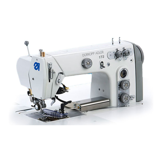
Performance description 2 Performance description The Dürkopp Adler 171 and 173 are, respectively, single- and twin-needle double chain stitch crossline sewing machines for linear seams, using stitch type 401. 2.1 Features Common features of the 171 and 173 • Mounted drive motor with corresponding controller (DAC eco or DAC classic - depending on the submodel) •... -
Page 10: Declaration Of Conformity
Max. sewing thread strength 70/3 (core spun thread) Max. stitch length (forwards only) [mm] 1 - 4 Needle gauge [mm] 0.4 - 15 (with conversion kit 0175 5900074) Roller top feed length [mm] 1 - 7 Operating manual 171/173 Version 01.0 - 01/2016... - Page 11 Rated power [kVA] 2.4 Additional equipment Using a flexible system of additional equipment, the machine can be equipped optimally and cost-effectively to suit the relevant application. = Standard equipment = Optional extension Operating manual 171/173 Version 01.0 - 01/2016...
-
Page 12: Additional Equipment
0 - 20 mm 011035 Edge stop right, swivels upwards, secured N900 to the cloth pressure bar connector, 020031 adjustable width 0 - 50 mm Operating manual 171/173 Version 01.0 - 01/2016... - Page 13 Maintenance unit 9780 000108 Sewing lamp (halogen) 9822 510003 Sewing light transformer with 0798 feeder for 230 V without switch 500088 Operating manual 171/173 Version 01.0 - 01/2016...
- Page 14 Steel carrier roller 1 mm, pyramid-tooth 0933 cut, 15 mm wide 005737 Steel carrier roller 2 mm, saw-tooth cut, 0933 15 mm wide 005738a Roller retrofit kit MG55 007914 Operating manual 171/173 Version 01.0 - 01/2016...
-
Page 15: Safety Instructions
20 mm and secure it against slipping off. Set-up The connecting cable must have a power plug approved in the specific country. The power plug may only be connected to the power cable by a qualified specialist. Operating manual 171/173 Version 01.0 - 01/2016... - Page 16 Safety equipment may not be removed or put out of service. If this equipment cannot be avoided for a repair operation, the safety equipment must be refitted and put back into service immediately afterwards. Operating manual 171/173 Version 01.0 - 01/2016...
-
Page 17: Signal Words And Symbols Used In Safety Instructions
In the case of dangers to personnel, the following symbols indicate the type of hazard: Signal word Type of danger General danger Danger due to electric shock Danger due to sharp objects Danger due to crushing Operating manual 171/173 Version 01.0 - 01/2016... - Page 18 Consequences in the event of noncompliance Measures for avoiding the danger This is what an environmental hazard note looks like for a hazard that could result in environmental dam- age if not complied with. Operating manual 171/173 Version 01.0 - 01/2016...
-
Page 19: Device Description
(4) - Needle bar with needle (5) - Adjusting wheel for the 2nd stitch length (stitch condensing) (6) - Adjusting wheel for normal stitch length for sewing (7) - Thread tensioner for looper thread (8) - Handwheel Operating manual 171/173 Version 01.0 - 01/2016... - Page 20 Device description Operating manual 171/173 Version 01.0 - 01/2016...
-
Page 21: Operation
1. Press the main switch (1) down to position I. The indicator lamp (2) lights up. To switch off the power: 1. Press the main switch (1) up to position 0. The indicator lamp (2) goes off. Operating manual 171/173 Version 01.0 - 01/2016... -
Page 22: Inserting And Replacing The Needle
2. Loosen the fastening screw (2). 3. Pull the needle out downwards. 4. Insert the new needle. 5. Important: Align the needle so that the groove (3) faces to the rear. 6. Tighten the fastening screw (2). Operating manual 171/173 Version 01.0 - 01/2016... -
Page 23: Threading The Needle Thread
(1). Important: The unwinding bracket (1) must be parallel to the reel stand (2). Fig. 5: Threading procedure for needle thread - General overview Operating manual 171/173 Version 01.0 - 01/2016... - Page 24 7. Insert the thread through the thread guide (4). 8. Insert the thread from the right to the left through the thread puller (5). Operating manual 171/173 Version 01.0 - 01/2016...
- Page 25 12. Feed the thread from above forwards and downwards to the rear through the thread guide (5) on the needle bar. 13. Insert the thread from the front to the back through the needle eye (6). Operating manual 171/173 Version 01.0 - 01/2016...
-
Page 26: Threading The Looper Thread
(1). Important: The unwinding bracket (1) must be parallel to the reel stand (2). Fig. 9: Threading procedure for looper thread - General overview Operating manual 171/173 Version 01.0 - 01/2016... - Page 27 7. Insert the thread from above downwards through the thread puller (6). 8. Guide the thread through the thread groove (7). To do this, pull the thread from the back under the cover plate of the groove. Operating manual 171/173 Version 01.0 - 01/2016...
- Page 28 14. Insert the thread from left to right through the looper hole (1) and pull out approx. 3 cm. 15. Press down the thread down-holder (3) and engage. 16. Fit the cover plates to the right and left of the throat plate. Operating manual 171/173 Version 01.0 - 01/2016...
-
Page 29: Threading Twin-Needle Machines
• 5.3 Threading the needle thread, pg. 21 • 5.4 Threading the looper thread, pg. 24 Important: Take care when threading the machine that the threads do not cross over one another. Operating manual 171/173 Version 01.0 - 01/2016... -
Page 30: Adjusting The Thread Tension And Quantity
Excessively tight tensions: The sewing material is pulled together • Looper thread tension too loose: Missed stitches The thread tension is adjusted using the adjusting wheels of the relevant thread tensioner on the machine column. Operating manual 171/173 Version 01.0 - 01/2016... -
Page 31: Adjusting The Needle Thread Quantity
The required thread quantity depends on the thickness of the sewing material, thread strength and seam type. For different threads and seam types, the threading procedure also differs ( pg. 23). Operating manual 171/173 Version 01.0 - 01/2016... - Page 32 2. Loosen the fastening screws (1) of the thread regulator (2). 3. Move the thread regulator (2) to the correct position. 4. Tighten the fastening screws (1) of the thread regulator (2). Operating manual 171/173 Version 01.0 - 01/2016...
-
Page 33: Adjusting The Looper Thread Quantity
• Considerable enlargement of the stitch length for elastic seams Faults due to excessively large looper thread quantity • Missed stitches • Looper thread jumps off the thread pick-up disk Operating manual 171/173 Version 01.0 - 01/2016... - Page 34 The holes (3) must always remain above the bar (2) of the thread down-holder (1). 4. Tighten the fastening screws (6). 5. Return the upper part of the machine to the upright position. Operating manual 171/173 Version 01.0 - 01/2016...
-
Page 35: Adjusting The Stitch Length/Bottom Feed
(2) - Stitch length adjusting wheel Adjusting the stitch length 1. Turn the adjusting wheel (2): • To increase the stitch length: Turn the adjusting wheel counterclockwise. • To reduce the stitch length: Turn the adjusting wheel clockwise. Operating manual 171/173 Version 01.0 - 01/2016... - Page 36 Adjusting the stitch length on the 171-131610 The submodel 171-131610 does not have adjusting wheels for the stitch length. Here, the stitch length is adjusted on the machine underside. Fig. 18: Adjusting the bottom feed/stitch length on the 171-131610 back front ①...
-
Page 37: Adjusting The Stitch Condensing
Adjusting the stitch length for stitch condensing: 1. Turn the adjusting wheel (2): • To increase the stitch length: Turn the adjusting wheel counterclockwise. • To reduce the stitch length: Turn the adjusting wheel clockwise. Operating manual 171/173 Version 01.0 - 01/2016... -
Page 38: Adjusting The Top Feed
Adjusting the top feed length 1. Turn the adjusting wheel (1): • For a larger top feed length: Turn the adjusting wheel counterclockwise. • For a smaller top feed length: Turn the adjusting wheel clockwise. Operating manual 171/173 Version 01.0 - 01/2016... -
Page 39: Adjusting The Contact Pressure Of The Carrier Roller
3. Tighten the screw (2). Separating the thread chain without a thread cutter For machines without a thread cutter, the fabric deflector (4) can be used during linking as a cutting knife for the thread chain. Operating manual 171/173 Version 01.0 - 01/2016... -
Page 40: Lifting The Carrier Roller
1. Pull the hand lever (1) to the front. The lever engages. The roller is completely raised. 2. Push the hand lever (1) to the back. The lever disengages. The roller is lowered. Operating manual 171/173 Version 01.0 - 01/2016... -
Page 41: Setting The Sewing Foot Pressure
Setting the sewing foot pressure: 1. Turn the adjusting wheel (1): • To increase the sewing foot pressure: Turn the adjusting wheel (1) clockwise. • To reduce the sewing foot pressure: Turn the adjusting wheel (1) counterclockwise. Operating manual 171/173 Version 01.0 - 01/2016... -
Page 42: Lifting The Sewing Foot
Do not put your hands underneath the lifted sewing foot. Lowering the sewing foot 1. Release the knee lever (1) or bring the pedal (2) back into the neutral position. The sewing foot lowers. Operating manual 171/173 Version 01.0 - 01/2016... -
Page 43: Locking The Sewing Foot In The Upper Position
Do not put your hands underneath the sewing foot when the lock is being canceled. 1. Push the knee lever to the right again or press the pedal half-way back. The sewing foot is lowered. The lock is canceled. Operating manual 171/173 Version 01.0 - 01/2016... -
Page 44: Keypad On The Machine Arm
As long as the roller is raised, the yellow LED next to the button lights up. Yellow LED Lights when function is activated. Green LED Lights when the sewing drive is switched on. Operating manual 171/173 Version 01.0 - 01/2016... -
Page 45: Operating The Controller
(1) - Pedal position +1: (3) - Pedal position -1: Sewing active Raises the sewing foot (2) - Pedal position 0: (4) - Pedal position -2: Rest position Sews an end strip and cuts thread Operating manual 171/173 Version 01.0 - 01/2016... - Page 46 1. Press the foot pedal back completely to pedal position -2 and hold it there. The thread is cut. The machine stops. Needle and sewing foot are raised. 2. Remove the sewing material. Operating manual 171/173 Version 01.0 - 01/2016...
-
Page 47: Maintenance
• Area around the thread pick-up disk • Bobbin housing Every 8 operating hours • Thread cutter • Area around the needle • Air inlet openings on the motor fan sieve • Oil pan Every 40 operating hours Operating manual 171/173 Version 01.0 - 01/2016... -
Page 48: Checking The Pneumatic System
Machine damage possible due to incorrect pressure. Incorrect pressure can cause damage to the machine. Check the pressure on a daily basis. Have the pressure adjusted by qualified specialists if the pressure deviates from the reference value. Operating manual 171/173 Version 01.0 - 01/2016... - Page 49 Machine damage possible due to excess water. Excess water can cause damage to the machine. Check the water level every day and drain the condensation water if there is too much water in the water separator. Operating manual 171/173 Version 01.0 - 01/2016...
-
Page 50: Oil Lubrication
Oil to be used: Only DA 10 or an oil of equivalent quality that has the following properties may be used for the machine: • Viscosity at 40 °C: 10 mm²/s • Flash point: 150 °C Operating manual 171/173 Version 01.0 - 01/2016... - Page 51 1. Switch off the sewing machine at the main switch. 2. Pour in oil, up to but not past the maximum level marking (2). 3. Switch on the sewing machine at the main switch. Operating manual 171/173 Version 01.0 - 01/2016...
- Page 52 4. Pour in oil, up to but not past the maximum level marking (3). 5. Tighten the locking screw (1). 6. Return the upper part of the machine to the upright position. 7. Switch on the sewing machine at the main switch. Operating manual 171/173 Version 01.0 - 01/2016...
-
Page 53: Customer Service
Contacts for repair in the event of damage to the machine: Dürkopp Adler AG Potsdamer Str. 190 33719 Bielefeld, Germany Tel. +49 (0) 180 5 383 756 Fax +49 (0) 521 925 2594 Email: service@duerkopp-adler.com Internet: www.duerkopp-adler.com Operating manual 171/173 Version 01.0 - 01/2016... - Page 54 Operation Operating manual 171/173 Version 01.0 - 01/2016...
-
Page 55: Set-Up
(1) - Machine upper section (6) - Setpoint device (2) - Table plate (7) - Maintenance unit (3) - Drawer (8) - Controller (4) - Frame (9) - Reel stand (5) - Pedal Operating manual 171/173 Version 01.0 - 01/2016... -
Page 56: Removing The Transport Securing Devices
All transport securing devices must be removed prior to set-up. 1. Remove the lashing straps and wooden blocks from the machine upper section, the table and the frame. 2. Remove the supporting wedges between the machine arm and throat plate. Operating manual 171/173 Version 01.0 - 01/2016... -
Page 57: Fitting The Frame Components
Important: The frame must sit evenly on the ground with all 4 feet. 6. Tighten all 8 fastening screws (8). 7. Screw the oil can holder (2) at the rear to the upper cross bar (4). Operating manual 171/173 Version 01.0 - 01/2016... -
Page 58: Completing The Table Plate
Fig. 34: Completing the table plate ① ② ⑥ ⑤ ④ ③ (1) - Upper section support (only on 171) (4) - Cable duct (2) - Rubber mounts (5) - Oil pan (3) - Drawer (6) - Corners Only on 171: 1. -
Page 59: Fastening The Table Plate To The Frame
1. Secure the table plate with wood screws (B8 x 35) onto the frame, in accordance with the dimensions on the diagram. Fig. 35: Dimensions for fastening the table plate to the frame Operating manual 171/173 Version 01.0 - 01/2016... -
Page 60: Installing The Reel Stand
2. Fasten the reel stand (1) with nut and washer. 3. Screw the thread reel holder (3) and the unwinding bracket (2) onto the reel stand (1) so that they are precisely parallel to one another. Operating manual 171/173 Version 01.0 - 01/2016... -
Page 61: Setting The Working Height
2. Set the table plate to the desired height. Important: Pull out or push in the table plate evenly at both sides to prevent it from jamming. 3. Tighten the screws (1) on the head sections. Operating manual 171/173 Version 01.0 - 01/2016... -
Page 62: Fitting The Machine Upper Section
(2) in the rubber inlays. 2. Tilt the upper part of the machine backwards. 3. Important: Remove the protective bar (1) and support screws (3). 4. Straighten up the upper part of the machine. Operating manual 171/173 Version 01.0 - 01/2016... -
Page 63: Fitting The Controller
1. Screw the control (3) onto the 4 screw holders (2) under the table plate. 2. Clamp the power cable of the control into the strain relief mechanism (1). 3. Screw the strain relief mechanism (1) under the table plate. Operating manual 171/173 Version 01.0 - 01/2016... -
Page 64: Fitting The Control Panel For The Controller
Fig. 41: Fitting the control panel - Part 2 ⑥ (6) - Arm cover fastening screws 4. Secure the control panel bracket to the arm cover using the arm cover fastening screws (6). 5. Position the arm cover including control panel. Operating manual 171/173 Version 01.0 - 01/2016... - Page 65 (7) - Cable inlet Laying the control panel cable 6. Laying the cable behind the rear of the arm cover. Important: Note the different cable inlets (7) of the 171 and 173. 7. Guide the cable down under the handwheel cover.
-
Page 66: Fitting The Pedal And Setpoint Device
5. Hang the pedal rod (4) with the ball socket on the setpoint device (2) and the pedal (5). 6. Pull the pedal rod (4) to the correct length: Correct setting: 10° inclination with pedal (5) released 7. Tighten the screw (3). Operating manual 171/173 Version 01.0 - 01/2016... -
Page 67: Fitting The Knee Lever
2. Fit the transmission rod (3) in the oil pan. 3. Screw the knee lever (1) rods together. 4. Guide the rod (1) through the hole in the oil pan (2) and connect it to the transmission rod (3). Operating manual 171/173 Version 01.0 - 01/2016... -
Page 68: Fitting The Oil Return Line
3. Important: Lay and secure the oil hose (2) such that it does not come into contact with any moving parts. 4. Return the upper part of the machine to the upright position. Operating manual 171/173 Version 01.0 - 01/2016... -
Page 69: Electrical Connection
To do this, read the operating manual for the DAC eco or DAC classic controller. The operating manual is provided in the controller accessory pack. You can also find the operating manual for the controller in the download area at www.duerkopp-adler.com. Operating manual 171/173 Version 01.0 - 01/2016... -
Page 70: Establishing Equipotential Bonding
1. Secure earthing cable (2) to the connection point on the controller (3). 2. Guide the earthing cable (2) upwards. 3. Secure earthing cable (2) with screw and tab connector to the connection point on the machine base plate (1). Operating manual 171/173 Version 01.0 - 01/2016... -
Page 71: Pneumatic Connection
2. Connect the machine hose (4) coming out of the upper section to the maintenance unit (3) at the top right. 3. Connect the system connection hose (2) to the pneumatic system. Operating manual 171/173 Version 01.0 - 01/2016... -
Page 72: Setting The Operating Pressure
Turn the rotary handle (1) clockwise. • To reduce the pressure: Turn the rotary handle (1) counterclockwise. 3. Push the turning handle (1) down. 6.15 Oil lubrication 5.16.1 Oil lubrication, pg. 48. Operating manual 171/173 Version 01.0 - 01/2016... -
Page 73: Sewing Test
8. Adjust the stitch and feed length ( pg. 33 and pg. 36) with respect to the sewing material. 9. Start the sewing test at low speed. 10. Increase the sewing speed continuously until the working speed is reached. Operating manual 171/173 Version 01.0 - 01/2016... - Page 74 Set-up Operating manual 171/173 Version 01.0 - 01/2016...
-
Page 75: Decommissioning
5. Cover the control panel to protect it from soiling. 6. Cover the entire machine if possible to protect it from soiling and damage. Observe the necessary safety precautions for transport. Operating manual 171/173 Version 01.0 - 01/2016... - Page 76 Decommissioning Operating manual 171/173 Version 01.0 - 01/2016...
-
Page 77: Disposal
ALWAYS observe the legally prescribed regulations for disposal of oil. When disposing of the machine, be aware that it consists of a range of different materials (steel, plastic, electronic components, etc.). Observe the applicable national regulations for disposal. Operating manual 171/173 Version 01.0 - 01/2016... - Page 78 Disposal Operating manual 171/173 Version 01.0 - 01/2016...
-
Page 79: Appendix
9 Appendix Dimensions for manufacturing a table plate... - Page 80 Appendix Operating manual 171/173 Version 01.0 - 01/2016...
- Page 81 Appendix Operating manual 171/173 Version 01.0 - 01/2016...
- Page 82 Appendix Operating manual 171/173 Version 01.0 - 01/2016...
- Page 84 DÜRKOPP ADLER AG Potsdamer Str. 190 33719 Bielefeld Germany Phone +49 (0) 521 925 00 E-mail: service@duerkopp-adler.com www.duerkopp-adler.com...
Need help?
Do you have a question about the 171 and is the answer not in the manual?
Questions and answers